Table of Contents
Advertisement
Quick Links
Advertisement
Table of Contents

Related Manuals for Raisecom RC831-240E


Summary of Contents for Raisecom RC831-240E
- Page 1 RC831-240E User Manual...
- Page 2 Raisecom Technology Co., Ltd shall not be held liable for errors contained herein or direct, indirect, special, incidental or consequential damages in connection with the furnishing, performance, or use of this material.
-
Page 3: Contact Information
+86-10-82883305 Fax: +86-10-82883056 World Wide Web You can access the most current Raisecom product information on the World Wide Web at the following URL: http://www.raisecom.com Feedback Comments and questions about how the RC831-240E device works are welcomed. Please review the... -
Page 4: Table Of Contents
CONTENTS Release Notes------------------------------------------------------------------------------------------------- 6 General Safety Instructions ------------------------------------------------------------------------------ 7 Safety Symbols ---------------------------------------------------------------------------------------------------------------------7 Handling Energized Products ---------------------------------------------------------------------------------------------------7 General Safety Practices ------------------------------------------------------------------------------------------------------------------------ 7 Connection of AC Mains ------------------------------------------------------------------------------------------------------------------------- 8 Connection of DC Mains ------------------------------------------------------------------------------------------------------------------------- 8 Preventing Electrostatic Discharge Damage --------------------------------------------------------------------------------8 Chapter 1 Product Overview ------------------------------------------------------------------------- 1 Overview---------------------------------------------------------------------------------------------------------------------1 Function Features ---------------------------------------------------------------------------------------------------------1... -
Page 6: Release Notes
Release Notes Date of Release Manual Version Revisions 20071128 200704 REV.A... -
Page 7: General Safety Instructions
General Safety Instructions The following instructions serve as a general guide for the safe installation and operation of telecommunications products. Additional instructions, if applicable, are included inside the manual. Safety Symbols This symbol may appear on the equipment or in the text. It indicates potential safety hazards regarding product operation or maintenance to operator or service personnel. -
Page 8: Connection Of Ac Mains
be present inside certain products even when the power switch (if installed) is in the OFF position or a fuse is blown. For DC-powered products, although the voltages levels are usually not hazardous, energy hazards may still exist. Before working on equipment connected to power lines or telecommunication lines, remove jewelry or any other metallic object that may come into contact with energized parts. -
Page 9: Chapter 1 Product Overview
PDH multiplexer realizes the transmission of at most 8 lines of E1 service on 1 line of fiber. For the E1 tributary interface, RC831-240E provides 4 expansion slots. Together with Raisecom’s E1 service sub-card, V.35 service sub-card, Ethernet service sub-card or other services sub-cards, various multi-service configuration solutions can be flexibly realized with RC831-240E to meet customers’... - Page 10 User Manual or DC power supply RC831-240E-S2 Stand-alone device, 8 lines of E1 service provided by 4 expansion slots in which sub-cards like E-SUBM-FV35, E-SUBM-2FV35, E-SUBM-2FE, E-SUBM-FE4E1, E-SUBM-2E1, E-SUBM-4E1-BL, and etc. can be inserted, 1 optical interface, dual-strand, single-mode...
- Page 11 For example: RC831-240E-S1-AC indicates device with 220V AC power supply, while RC831-240E-S1-DC indicates device with -48V DC power supply. The devices that can communicate with RC831-240E series devices are listed in the table below. Client Site Device CO Site Device...
-
Page 12: Chapter 2 Technical Specifications
User Manual Chapter 2 Technical Specifications 2.1 Technical specifications of E1 interface Bit rate: 2048Kbps±50ppm Coding: HDB3 Frame format: comply with ITU-T G.704 recommendations Physical characteristic: comply with ITU-T G.703 recommendations Transfer characteristic: comply with ITU-T G.823 recommendations Jitter tolerance: comply with ITU-T G.823 recommendations 2.2 Technical specifications of the optical interface... -
Page 13: Power Supply
User Manual 2.4 Power supply AC power supply Voltage: 220V Allowance: 175 ~ 265V Frequency: 50Hz Voltage: 110V/230V Allowance: 85 ~ 265V Frequency: 50Hz/60Hz DC power supply Voltage: -48V Allowance: -36 ~ -72V Voltage: +24V Allowance: +18 ~ +36V Power consumption: <... -
Page 14: Chapter 3 Device Appearance And Descripiton
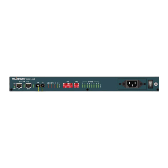
User Manual Chapter 3 Device Appearance and Descripiton 3.1 Device front panel Figure 3-1 The front panel of RC831-240E with AC power supply Figure 3-2 The front panel of RC831-240E with DC power supply 3.2 Device rear panel Figure 3-3 The rear panel of RC831-240E 3.3 Indicator Description... -
Page 15: Interface Description
User Manual L-LOF (Red): ON: loss of frame (LOF) alarm at the local optical interface R-LOF (Red): ON: loss of frame (LOF) alarm at the remote optical interface L-E-3 (Red): ON: the receiving signal bit error rate (BER) at the local optical interface exceeds 1E-3... -
Page 16: Expansion Slot Description
3.5 Expansion slot description RC831-240E has 4 expansion slots, and they are titled SLOT1, SLOT2, SLOT3 and SLOT4. Various expansion sub-cards can be inserted into these expansion slots to provide excellent configuration flexibility, and to meet different requirements from customers. - Page 17 User Manual (occupies E1 1~4) (occupies E1 5~8) E-SUBM-4E1-BL E-SUBM-4E1-BL (occupies E1 1~4) (occupies E1 5~8) Note: When the sub-cards in the expansion slot SLOT1 and SLOT3 are sub-cards that occupy 4 lines of E1, the expansion slot SLOT2 and SLOT4 can not be used.
-
Page 18: Chapter 4 Device Settings
Chapter 4 Device Settings 4.1 DIP switch description 4.1.1 The location of the DIP switches The DIP switches are placed on the front panel of RC831-240E, please see the figures that shows the device front panel. 4.1.2 DIP switch description There are 2 DIP switches on the front panel of the device: SW1 and SW2. - Page 19 User Manual E1 4 loopback E1 5 loopback E1 6 loopback E1 7 loopback E1 8 loopback All E1 loopback Note: The loopback control function provides two ways of loopback testing: single E1 loopback or all E1 loopback. When conducting single loopback testing, the communication of other E1 lines will not be affected.
- Page 20 COM port of a PC. The software online upgrade function makes device maintenance and upgrade easier. For a RC831-240E device under regular use, please do not change the status of the switch and keep its default setting (OFF). Otherwise, the improper setting of the switch may lead to operation abnormity.
-
Page 21: Default Settings
User Manual Bit 1 Bit 2 Bit 3 Bit 4 Address Code Remote device Local device 1 Local device 2 Local device 3 Local device 4 Local device 5 Local device 6 Local device 7 Local device 8 Local device 9... -
Page 22: Chapter 5 Basic Connection And Typical Application
User Manual Chapter 5 Basic Connection and Typical Application 5.1 Basic Connection 5.1.1 Connect the optical interface Insert the well-prepared fiber patch cord into the optical interface on the front panel of the device. The optical interface connection pattern is shown in Figure 5-1. -
Page 23: Typical Application
User Manual 5.2 Typical application Figure 5-2 Point-to-point application... -
Page 24: Chapter 6 Network Management Features
All indicator status information and expansion slot occupation status information of local/remote RC831-240E can be displayed on the network management platform. Users can query the working status information and alarm information of the local/remote RC831-240E and the sub-cards in the expansion slots of the device. -
Page 25: Chapter 7 Device Installation Preparation And Connection
7.1.1 Make sure that the cable applied matches the sub-cards on the device The 4 expansion slots on RC831-240E support various service sub-cards. Before electrifying the device, please make sure that the cable applied matches the sub-card model on the device. For detailed information, please refer to the user manual of the corresponding sub-card. -
Page 26: Device Electrifying
User Manual Please insert the SC patch cord into the optical interface and make sure that the connector touches the bottom of the interface. If the TX and RX direction of the optical signal is not known, users can connect the optical interface after electrifying the device. -
Page 27: Appendix A Cable Making
User Manual Appendix A Cable Making A.1 PC-Agent network management cable making For PC-Agent network management, please use flat straight-through cable with RJ-45 connector. The RJ-45 connector and its pin arrangement are shown in Figure A-1, Table A-1 and Table A-2 respectively. -
Page 28: Appendix B Faq
User Manual Appendix B FAQ For some problems you may meet during installation and operation, please try to solve them following the suggestions below. For the problems can not be solved using the following suggestions, please contact with distributors for technical support. - Page 29 Address: 2 Floor, South Building of Rainbow Plaza, No.11 Shangdi Information Road, Haidian District, Beijing Postcode: 100085 Tel: +86-10-82883305 Fax: +86-10-82883056 Email: export@raisecom.com http://www.raisecom.com...
Need help?
Do you have a question about the RC831-240E and is the answer not in the manual?
Questions and answers