Table of Contents
Advertisement
Quick Links
Advertisement
Table of Contents

Related Manuals for Raisecom RC831-60-FV35 Series


Summary of Contents for Raisecom RC831-60-FV35 Series
- Page 1 RC831-60-FV35 User Manual...
- Page 2 Raisecom Technology Co., Ltd shall not be held liable for errors contained herein or direct, indirect, special, incidental or consequential damages in connection with the furnishing, performance, or use of this material.
-
Page 3: Contact Information
Tel: +86-10-82883305 Fax: +86-10-82883056 World Wide Web You can access the most current Raisecom product information on the World Wide Web at the following URL: http://www.raisecom.com Feedback Comments and questions about how the RC831-60-FV35(A) device works are welcomed. Please review the FAQ in the related manual, and if your question is not covered, send email by using the following web page: http://www.raisecom.com/en/xcontactus/contactus.htm. -
Page 4: Table Of Contents
CONTENTS Release Notes------------------------------------------------------------------------------------------------- 5 General Safety Instructions ------------------------------------------------------------------------------ 6 Safety Symbols ---------------------------------------------------------------------------------------------------------------------6 Handling Energized Products ---------------------------------------------------------------------------------------------------6 General Safety Practices ------------------------------------------------------------------------------------------------------------------------ 6 Connection of AC Mains ------------------------------------------------------------------------------------------------------------------------- 7 Connection of DC Mains ------------------------------------------------------------------------------------------------------------------------- 7 Preventing Electrostatic Discharge Damage --------------------------------------------------------------------------------7 Chapter 1 Product Overview ------------------------------------------------------------------------- 1 Overview---------------------------------------------------------------------------------------------------------------------1 Function Features ---------------------------------------------------------------------------------------------------------1... -
Page 5: Release Notes
Release Notes Date of Release Manual Version Revisions 20071114 200706 REV.A... -
Page 6: General Safety Instructions
General Safety Instructions The following instructions serve as a general guide for the safe installation and operation of telecommunications products. Additional instructions, if applicable, are included inside the manual. Safety Symbols This symbol may appear on the equipment or in the text. It indicates potential safety hazards regarding product operation or maintenance to operator or service personnel. -
Page 7: Connection Of Ac Mains
be present inside certain products even when the power switch (if installed) is in the OFF position or a fuse is blown. For DC-powered products, although the voltages levels are usually not hazardous, energy hazards may still exist. Before working on equipment connected to power lines or telecommunication lines, remove jewelry or any other metallic object that may come into contact with energized parts. -
Page 8: Chapter 1 Product Overview
RC831-60-FV35 is a stand-alone single-optical-port PDH multiplexer independently developed by Raisecom Technology Co., Ltd. RC831-60-FV35 is a fiber transmission device aiming at network access market. It can multiplex at most 1 line of E1 data and 1 line of V.35 data up to 1 line of fiber and realize remote network management at the same time. - Page 9 User Manual single power supply, 220V AC power supply. RC831-60-FV35-S1-AC Stand-alone device, 1 line of V.35 signal, 1 line of E1 signal including both 75Ω unbalanced E1 interface (BNC) and 120Ω balanced E1 interface (RJ-45), 1 optical interface, dual-strand, single-mode, transmission distance 0~25km, single power supply, 220V AC power supply.
- Page 10 User Manual RC831-60-FV35-M-DC Stand-alone device, 1 line of V.35 signal, 1 line of E1 signal including both 75Ω unbalanced E1 interface (BNC) and 120Ω balanced E1 interface (RJ-45), 1 optical interface, dual-strand, multi-mode, transmission distance 0~2km, single power supply, -48V DC power supply.
- Page 11 User Manual including both 75Ω unbalanced E1 interface (BNC) and 120Ω balanced E1 interface (RJ-45), 1 optical interface, single-strand, two-wavelength, optical interface wavelength 1550nm, transmission distance 10~50km, single power supply, -48V DC power supply. Note: Among RC831 series devices with optical transceivers for dual-strand fiber, the devices with same optical transceivers can inter-connect with each other.
-
Page 12: Chapter 2 Technical Specifications
User Manual Chapter 2 Technical Specifications 2.1 Technical specifications of E1 interface Bit rate: 2048Kbps±50ppm Coding: HDB3 Interface type: BNC, RJ-45 Interface impedance: 75Ω unbalanced interface, 120 Ω balanced interface Physical characteristic: comply with ITU-T G.703 recommendations Transfer characteristic: comply with ITU-T G.823 recommendations Jitter tolerance: comply with ITU-T G.823 recommendations... -
Page 13: Operating Environment
User Manual Voltage: 110V/230V Allowance: 85 ~ 265V Frequency: 50Hz/60Hz DC power supply Voltage: -48V Allowance: -36 ~ -72V Voltage: +24V Allowance: +18 ~ +36V Power consumption: < 10W 2.4 Operating environment Operating temperature: 0 ~ 60℃ Operating humidity: ≤ 90% (25℃) 2.5 Storing environment... -
Page 14: Chapter 3 Device Appearance And Descripiton
User Manual Chapter 3 Device Appearance and Descripiton 3.1 Device front panel 3.2 Device rear panel RC831-60-FV35 with AC power supply: RC831-60-FV35 with DC power supply:... -
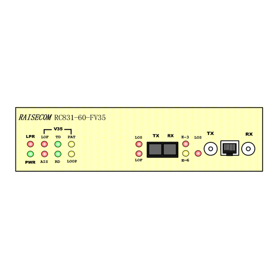
Page 15: Indicator Definition
User Manual 3.3 Indicator definition The indicators on the device front panel show the current working status of device power supply, optical interface, and E1 interface. The definition of the indicators is described in the table below: Number Indicator... - Page 16 User Manual ON: local AIS alarm only OR alarm occurs on both local and remote site Flickering: remote AIS alarm only Green V.35 interface TD signal indicator Flickering: There is TD signal (transmission data) data flow at the V.35 interface. The frequency of the flicker depends on the bit rate of the interface.
-
Page 17: Interface Description
User Manual ON: local optical interface receiving signal Loss of Frame (LOF) alarm Flickering: remote optical interface receiving signal LOF alarm ON: local optical interface loss of receiving signal alarm Flicking: remote optical interface loss of receiving signal alarm... - Page 18 User Manual One V.35 interface is located on the rear panel of the device. It is described in the table below: Interface Interface Type Description V.35 interface Local V.35 interface.
-
Page 19: Chapter 4 Device Settings
User Manual Chapter 4 Device Settings 4.1 DIP switch description 4.1.1 DIP switch location 1 2 3 4 1 2 3 4 1 2 3 4 1 2 3 4 1 2 3 4 1 2 3 4 1 2 3 4 The bottom view of the device 4.1.2 DIP switch description... - Page 20 User Manual 4.1.2.1 Timeslot configuration DIP switch SW1~4 In the tables below, “√” indicate Enable; “×” indicates Disable. SW1 definition (default all OFF) Bit 1 Bit 2 Bit 3 Bit 4 Bit 5 Bit 6 Bit 7 Bit 8 Definition V.35 Channel...
- Page 21 User Manual the same time. Only when at least 1 timeslot is enabled, will the framing be realized. 4.1.2.2 Function setting switch SW5 In the tables below, “√” indicate Enable; “×” indicates Disable. SW5 definition: Bit 1 Bit 2...
- Page 22 User Manual framing mode (PCM30/PCM31) setting of the local device will automatically follow the setting of the remote device. Bit 4: bit error testing enable/disable switch BERT (default OFF) Bit 4 BERT Enable the inbuilt bit error testing function Disable the inbuilt bit error testing function There is an inbuilt bit error testing unit in the device.
- Page 23 User Manual Note: The phase relation of the TX CLK signal and TD signal of this device is self-adjusted. There is no need for user setting. Bit 6: fault pass-through function switch (default OFF) Bit 6 Fault pass-through function...
- Page 24 User Manual Set up the “remote loopback” on the local PDH multiplexer Fiber BER Tester Remot Local Set up the “local loopback” on the local PDH multiplexer Note: 1. When setting up remote loopback testing, please make sure that there is no alarm at the optical interface in advance.
-
Page 25: Default Settings
User Manual 4.1.3 Default settings The default status of the Bit 1 and Bit 2 of SW5 is ON. The settings of Bit 5~8 of SW6 follow the rule in the table below according the optical transceivers the device applies. The factory setting for the bits of SW7 is ON, ON, ON, OFF, that is, the E1 interface is a 75Ω... -
Page 26: Chapter 5 Basic Connection And Typical Application
User Manual Chapter 5 Basic Connection and Typical Application 5.1 Basic connection 5.1.1 Connect the optical interface Insert the well-prepared fiber patch cord into the optical interface on the front panel of the device. For device adopting optical transceivers M, S1, S2 or S3, the optical interface connection pattern is shown in the figure below. -
Page 27: Connect The E1 Interface
User Manual Note: Only inter-connection of optical transceiver SS13 and SS15 and inter-connection of optical transceiver SS23 and SS25 are allowed. Same type of optical transceivers can not communicate. If the connection is correct, and there is receiving optical signal, the LOS alarm indicator on the front panel of the device will turn OFF after the device being electrified. -
Page 28: Point-To-Point "V.35 Terminal Clock - Line-In Clock" Structure
User Manual 5.2.2 Point-to-point “V.35 terminal clock – line-in clock” structure When the remote DTE device following the clock of local DTE device, that is, the TX CLOCK of local DTE serves as the internal clock source, users can set the clock of local PDH multiplexer with V.35 device to V.35 terminal clock mode and set the clock of remote PDH multiplexer with V.35... -
Page 29: Chapter 6 Network Management Features
6.1 Network management platform RC831-60-FV35 can only be used as remote site device and be managed on the network management platform NView NNM V5.0 developed by Raisecom. Through the network management platform, users can view the status information of RC831-60-FV35, and control and configure it. -
Page 30: Chapter 7 Device Installation Preparation And Connection
User Manual Chapter 7 Device Installation Preparation and Connection 7.1 Pre-installation checking and preparing Firstly, please check the model and the number of the device and spare parts according to the packing list. Please be sure that the appearance of the device is intact. If there is any evidence that the device has been affected by damp, please dry it before installation. - Page 31 User Manual is, connect the terminal in the middle of the DC power supply interface to the protection earth at first. Before electrifying, please connect the “-48V” terminal with cable of lower electrical potential and connect the “BGND” terminal with cable of higher electrical potential.
-
Page 32: Appendix A Cable Making
User Manual Appendix A Cable Making A.1 E1 cable making For 75Ω BNC interface: The application of coaxial cable of model SYV75-5, SYV75-3 or SYV75-2-2 is recommended. Please keep the maximal length of the cable within 200 meters. Take out the BNC connector from the appendix pack of the device, and screw off the protection cover. - Page 33 User Manual Note: When making cables, please adopt shielded cable in preference to meet the electromagnetic compatibility requirements.
-
Page 34: Appendix B Faq
User Manual Appendix B FAQ For some problems you may meet during installation and operation, please try to solve them following the suggestions below. For the problems can not be solved using the following suggestions, please contact with distributors for technical support. - Page 35 User Manual Please check whether the E1 cable has been connected properly, and whether the TX and RX of the BNC cable are correctly connected.
- Page 36 Address: 2 Floor, South Building of Rainbow Plaza, No.11 Shangdi Information Road, Haidian District, Beijing Postcode: 100085 Tel: +86-10-82883305 Fax: +86-10-82883056 Email: export@raisecom.com http://www.raisecom.com...
Need help?
Do you have a question about the RC831-60-FV35 Series and is the answer not in the manual?
Questions and answers