Table of Contents
Advertisement
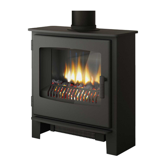
Installation & Operating Instructions
Model: Gas Q7
Variants Covered: Ignite (CD1), Hereford (CD2) &
Desire (SD1)
Conventional Flue Natural Gas Stove
Top Flue Outlet Only
PLEASE LEAVE THESE INSTRUCTIONS WITH THE
END USER
Chimney closure plates are not supplied
Please note gas installations MUST only be carried out by installers who
are Gas Safe registered.
200747_1
Advertisement
Table of Contents

Related Manuals for Broseley Gas Q7


Summary of Contents for Broseley Gas Q7
- Page 1 Installation & Operating Instructions Model: Gas Q7 Variants Covered: Ignite (CD1), Hereford (CD2) & Desire (SD1) Conventional Flue Natural Gas Stove Top Flue Outlet Only PLEASE LEAVE THESE INSTRUCTIONS WITH THE END USER Chimney closure plates are not supplied Please note gas installations MUST only be carried out by installers who are Gas Safe registered.
-
Page 2: Table Of Contents
Contents Introduction Packing List Specification Dimensions Hearth Requirements Chimney Requirements Assembly Burner Installation Mica Board Installation Connecting the TTB Sensor Fitting the Decorative log retainer Positioning the logs 10-13 Gas Connection & Pressure Testing Spillage Testing Maintenance Operating the Stove Cleaning the Stove Curing the Paint Trouble-shooting... -
Page 3: Introduction
Introduction THANK YOU FOR PURCHASING A BROSELEY GAS STOVE Broseley Fires Ltd, a family run company, was founded as an appliance and design development company in 1975. Since then we have built up an enviable reputation for the quality, reliability and fuel efficiency of our stoves. -
Page 4: Specification
Specification Heat Input (Gross) 6.8kW Gas Category Supply Pressure 20 mbar Gas Rate 0.66 m Injector Size 125mm (5”) Flue diameter Country of destination GB, IE Efficiency Class Class 2 Nominal Output 4.7kW NOx Class Please note this product is designed to only use natural gas G20. Dimensions Ignite CD1 Q7 - WEIGHT 75 Kg Hereford CD2 Q7 –... -
Page 5: Hearth Requirements
Hearth Requirements The appliance needs to be located onto a solid non-combustible hearth with a minimum thickness of 12mm. The hearth must be capable of withstanding the weight of the appliance. To ensure correct combustion the following minimum clearances must be adhered to NB Measurements taken from the Lid of the stove (Dimension C on page 4): Material... -
Page 6: Chimney Requirements
Chimney Requirements Please note Broseley Fires do not provide flue pipes, closure plates or any other associated accessory. Top Flue Outlet Only The stove must be installed in accordance with current gas and buildings regulations BS5871: Part1. The appliance can be installed in any adequate area suitable for solid fuel fires and stoves. -
Page 7: Burner Installation
Assembly - Burner Installation Ensure all components are present prior to commencing assembly (See Packing List on page 3). You will need a pozi drive screwdriver. 1) Remove the stove body from its packaging and stand it in position. 2) Open the main door. 3) Insert the burner end with the control knob first followed by the other end of the burner locating the burner bracket onto the side fixing points. - Page 8 Assembly – Mica Boards First fit the rear mica board behind the burner bracket as shown above and secure through the burner fixing points using the 2 x No.6 x 25 self -tapping screws provided. Now fit one of the side mica boards Next rest the top mica board onto ensuring that the board is snug the side board (this board will...
- Page 9 Assembly - Fitting TTB sensor With the burner installed, thread the wires from the interrupter to the TTB device (mounted on the rear panel of the stove). These wires can be installed either way round on the terminals. 200747_1...
- Page 10 Assembly – Decorative Log Retainer Using the 2 off M6 Nut and Bolts provided, locate the decorative trim behind the stove opening as shown and secure in position. 200747_1...
-
Page 11: Positioning The Logs
Before any ceramics are placed in position ensure that the pilot is not obstructed and the burner is operating correctly. Broseley Fires Ltd accepts no responsibility for any injury sustained whilst handling hot ceramics. Ceramics which are found to be placed other than in accordance with these instructions will result in a charge being made following any service callout. - Page 12 Assembly - Positioning the Logs 4: Place the side left fibre in position, the fibre slides into position to the side of the front left ceramic and rests against the fuel 5: Place the side right fibre in position, the fibre slides into position to the side of the front right ceramic and rests against the fuel bed...
- Page 13 Assembly - Positioning the Logs 7: Place Log J as shown, seating it between the side right fibre and the fuel bed 8: Place Log E so as to locate behind Log J 9: Place Log B ensuring that the thin end does not obstruct the front ports on the burner 200747_1...
- Page 14 Assembly - Positioning the Logs 10: Place log F and H ensuring that log F does not obstruct the front burner ports 11: Place log C in position ensuring that the forked ends rest upon both the left and right hand front coals 12: Place Log G and A in position as shown.
-
Page 15: Gas Connection & Pressure Testing
Assembly - Gas Connection & Pressure Testing A minimum 15mm-diameter gas supply pipe must be used to within 1 metre of the installation with the final connection to the stove to be completed with the suitable 8mm semi-rigid gas pipe. The 8mm pipe should be connected to the inlet of the gas valve using the nut and 8mm olive provided. -
Page 16: Spillage Testing
Spillage Testing A Spillage Test MUST be made before the installed fire is left with the customer. Carry out the test by first closing all doors and windows in the room containing the fire. Insure that the fire is burning at full rate for a minimum of 10-15 minutes. Using a lighted smoke match, run it along under the rear edge of the stove. -
Page 17: Maintenance
Maintenance Door adjustment In the case of the door rope not providing an adequate seal to the room, products of combustion may enter the room (see warning notes), to ensure an adequate seal the door may need to be periodically adjusted as the rope seal wears with use. -
Page 18: Operating The Stove
Operating the Stove It is important to read these instructions thoroughly before lighting the stove. The gas stove operates with a traditional permanent pilot light. The knob for ignition and power control are located on the lower right hand side of the stove, the indicator in the plate shows the knob position (Marked on knob) The pilot light is located at the left corner of the coal matrix. -
Page 19: Cleaning The Stove
Cleaning the stove We recommend only doing this when the stove is cold using a soft brush to clean any of the stove surfaces, this is normally sufficient to remove dust. For stubborn marks you can use a damp lint free cloth, ensure that all surfaces are dried off immediately. -
Page 20: Trouble-Shooting
Trouble-shooting The gas pilot will not ignite or stay lit Ensure the gas is turned on at the appliance and the meter / cylinder. Hold the pilot gas button for at lest 20 seconds once the pilot is alight to ensure the operation of the safety thermocouple valve. -
Page 21: Servicing
Servicing Instructions Servicing should be carried out annually by a qualified installation engineer. Remove the coals and clean any dust and debris from the top of the burner unit. Ideally a vacuum cleaner should be used, but a soft brush will do. Check the condition of the coals. -
Page 22: Commissioning Form
Commissioning Form THIS SECTION MUST BE COMPLETED AND SIGNED BY THE INSTALLATION ENGINEER PLEASE LEAVE WITH THE CUSTOMER AND THE APPLIANCE. Size of Governor setting: (i.e.) Natural Gas 20mbar. Length and size of gas supply: _______________ Meter pressure Fire only on: ________________ All Other appliances on: __________________ Burner pressure Fire only on: _______________ All Other appliances on: __________________... -
Page 23: Guarantee
Please retain your purchase receipt. We will need to see this in the event of a claim under warranty. Broseley Fires Ltd, First Floor, Bemodern Ltd. Unit B Knights Court,... -
Page 24: Notes
Notes 200747_1...
Need help?
Do you have a question about the Gas Q7 and is the answer not in the manual?
Questions and answers