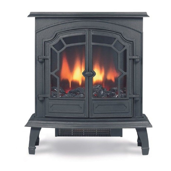
Broseley Canterbury Installation, Servicing And Operation Manual
Slim line gas stove
Hide thumbs
Also See for Canterbury:
- Installation & operating instructions manual (19 pages) ,
- Installation and operation manual (19 pages) ,
- Installation & operating instructions manual (19 pages)
Table of Contents
Advertisement
Quick Links
Installation, Servicing and Operation Manual
C
a
n
t
e
r
b
C
a
n
t
e
r
b
L
i
n
c
o
L
i
n
c
o
This book contains fitting, servicing and operation instructions for the
Broseley Fires Canterbury and Lincoln slim line gas stoves.
Natural Gas and Propane instructions are included in this book.
PLEASE LEAVE THESE INSTRUCTIONS WITH THE
Revision: GB08a
u
r
y
S
l
i
m
u
r
y
S
l
i
m
l
n
S
l
i
m
L
l
n
S
l
i
m
USER
L
i
n
e
G
L
i
n
e
G
&
&
i
n
e
G
a
L
i
n
e
G
a
a
s
S
t
o
v
a
s
S
t
o
v
s
S
t
o
v
e
s
S
t
o
v
e
e
e
Advertisement
Table of Contents

Related Manuals for Broseley Canterbury


Summary of Contents for Broseley Canterbury
- Page 1 Installation, Servicing and Operation Manual & & This book contains fitting, servicing and operation instructions for the Broseley Fires Canterbury and Lincoln slim line gas stoves. Natural Gas and Propane instructions are included in this book. PLEASE LEAVE THESE INSTRUCTIONS WITH THE USER...
-
Page 2: General Installation Requirements
Introduction THANK YOU FOR PURCHASING A GAS FIRED STOVE Broseley Fires Ltd, a family run company, was founded as an appliance and design development company in 1975. Since then we have built up an enviable reputation for the quality, reliability and fuel efficiency of our stoves. -
Page 3: Technical Information
4.3Kw Supply Pressure 20 mbar 37mbar Gas Rate 0.66 m3/Hr 0.25 m3/Hr Injector Size C.A.T. 16/360 C.A.T. 10/150 Stove Dimensions Canterbury Lincoln Height 655mm 660mm Height to centre of Spigot 470mm 460mm Depth (not inc. Ash Lip) 270mm 280mm Width... - Page 4 Sitting the Appliance Lintel Dimensions A = 250mm Min. B= 50mm Min. C = 50mm Min. D = 25mm Min. Void Closure Plate Figure 1 The gas supply connection to the appliance is in the centre underneath the stove. The connection requires an 8mm-diameter semi-rigid pipe, not more than 1 meter in length.
-
Page 5: Stove Assembly
2 x Spacers for burner (Used on Lincoln only) 3 x Self tapping screws for the stainless reflector The stove assembly is the same on both stoves Canterbury and Lincoln the only difference being the access to the stove. The Canterbury Stove is accessed through the main door via a threaded handle. -
Page 6: Fitting The Burner
Fitting the Burner 1) Insert the burner into the stove locating the burner bracket on to the fixing lugs provided. Insert the burner end with the control knob first followed by the other end of the burner locating the burner bracket onto the up stands provided. - Page 7 Fitting the Stainless Reflector Plate After fixing the burner in position fit the stainless reflector plate to the rear of the stove (dilution box) using the holes and fixing screws supplied. Remove the protective film once the plate has been fitted, this will insure no damage to the plate incurs.
-
Page 8: Flue Connection
Flue Connection Firstly you will need to attach the flue spigot to the rear of the stove using the 4 screws supplied. The stove must be installed in accordance with current gas and buildings regulations BS5871: Part1. Before you install the stove, make sure the chimney flue outlet is correctly positioned to align with the flue outlet on the stove and that the chimney is in good condition. -
Page 9: Pressure Testing
Replacement ceramics are available from your dealer. Whilst arranging the ceramics, ensure that the pilot is not obstructed. Broseley Fires Ltd accepts no responsibility for any injury sustained whilst handling hot ceramics. Before any ceramics are placed in position ensure that the burner is operating correctly. - Page 10 2. Position a coal on each of the platforms on the centre coal. 3. Place a coal on either side, resting on the coal bed and the loose coal beside it. Next to this, bridge the gap between the front and the middle row either side of he center.
- Page 11 Arranging the Layout of the Coals - Propane 1) Position the first large coal matrix on the burner as shown. This coal matrix sits directly on the burner. 2) Position the second large coal matrix at the back of the burner resting on the first coal matrix as shown 3) Position 4 ceramic coals in between the up stands of the first ceramic base.
-
Page 12: Test For Spillage
4) Place the final layers of coals bridging the gap between the first and second large coal matrixes. These should not be forced into position just placed carefully as shown. Test for Spillage A Spillage Test MUST be made before the installed fire is left with the customer. Carry out the test by first closing all doors and windows in the room containing the fire. -
Page 13: Operating The Stove
THE FOLLOWING ARE IMPORTANANT WARNINGS RELATIVE TO THE SPILLAGE MONITORING SYSTEM 1. The installer must not attempt any adjustments to the spillage monitoring system. 2. There must be no attempt to disable the spillage monitoring system. 3. It is not possible to replace individual parts of the pilot assembly on the appliance –... -
Page 14: Troubleshooting
EXTINGUISHING THE STOVE FULLY 1. From any heat setting or the permanent pilot, depress control knob and turn clockwise to “OFF” position. Should the glass door become broken or damaged in any way, turn your stove off and do not attempt to re-light it. Contact your dealer for a replacement to be fitted before relighting the appliance. -
Page 15: Servicing Instructions
Servicing Instructions Servicing should be carried out annually by a qualified installation engineer when the stove is cold and the gas supply is turned off at the isolation tap. The following points should be checked. • Remove the coals and clean any dust and debris from the top of the burner unit. - Page 16 AND FINALLY…….. We would remind you that it is a legal requirement that the stove is installed by a qualified and accredited installation engineer. Improper installation, adjustment, alteration, service or maintenance can cause personal injury and / or damage to property.
- Page 17 The Commissioning Sheet THIS SECTION MUST BE COMPLETED AND SIGNED BY THE INSTALLATION ENGINEER PLEASE LEAVE WITH THE CUSTOMER AND THE APPLIANCE. Type gas supply (please tick) Natural (mains) Gas _______LPG supply in bulk_______ LPG supply in cylinder________ Size of Governor setting: (i.e.) Natural Gas 20MBAR.
- Page 18 The rights given in this guarantee are limited to the UK mainland and are in addition to any to which you may have a statutory entitlement. Please retain your purchase receipt. We will need to see this in the event of a claim under warranty. Broseley Fires Ltd Knights Way Battlefield Enterprise Park Shrewsbury...
Need help?
Do you have a question about the Canterbury and is the answer not in the manual?
Questions and answers