Table of Contents
Advertisement
Quick Links
Installation & Operating Instructions
For Gas Q5 Stoves
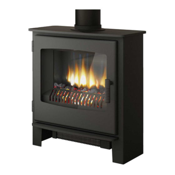
IGNITE 5 GAS STOVE – (CD1) MK2
HEREFORD 5 GAS STOVE – (CD2) MK2
DESIRE 5 GAS STOVE – (SD1) MK2
Remote or Manual Control
Conventional, Top or Rear Flue, Natural Gas Stove
IT IS A REGULATION THAT THESE INSTRUCTIONS ARE HANDED TO THE
CUSTOMER AFTER THE INSTALLATION IS COMPLETE. IT IS ALSO THE
RESPONSIBILTY OF THE INSTALLATION ENGINEER TO ENSURE THE
CUSTOMER IS ABLE TO FULLY OPERATE THE APPLIANCE AND IS AWARE
OF ANY CLEANING OR MAINTENANCE REQUIRMENTS.
Please note: Gas installations MUST only be carried out by installers who
are Gas Safe registered.
Warning
- Appliance should not be used if the glass in the door is
cracked, damaged or broken.
This product is not suitable for primary heating purposes.
200753_3TB Jan 2021
Advertisement
Table of Contents

Related Manuals for Broseley IGNITE 5 CD1 MK2


Summary of Contents for Broseley IGNITE 5 CD1 MK2
- Page 1 Installation & Operating Instructions For Gas Q5 Stoves IGNITE 5 GAS STOVE – (CD1) MK2 HEREFORD 5 GAS STOVE – (CD2) MK2 DESIRE 5 GAS STOVE – (SD1) MK2 Remote or Manual Control Conventional, Top or Rear Flue, Natural Gas Stove IT IS A REGULATION THAT THESE INSTRUCTIONS ARE HANDED TO THE CUSTOMER AFTER THE INSTALLATION IS COMPLETE.
-
Page 2: Table Of Contents
Contents Introduction Packing List Specification Dimensions Hearth Requirements Chimney Requirements Assembly Burner Installation Mica Board Installation Fitting the Decorative Log Retainer Connecting the TTB Sensor Manual Operated Stove Connecting the TTB Sensor Remote Control Operated Stove Positioning the logs 11 - 18 Gas Connection &... -
Page 3: Introduction
Introduction THANK YOU FOR PURCHASING A BROSELEY GAS STOVE Broseley Fires Ltd, a family run company, was founded as an appliance and design development company in 1975. Since then we have built up an enviable reputation for the quality, reliability and fuel efficiency of our stoves. -
Page 4: Specification
Specification Heat Input (Gross) 6.0kW Gas Category Supply Pressure 20 mbar Gas Rate 0.557 m Injector Size 7 x 0.73mm (Q5) 125mm (5”) Flue diameter Country of destination GB, IE Efficiency Class Class 1 Nominal Output 4.5kW 130 mg/kWh (GCV) Please note this product is designed to only use natural gas G20. -
Page 5: Hearth Requirements
Hearth Requirements The appliance needs to be located onto a solid non-combustible hearth with a minimum thickness of 12mm. The hearth must be capable of withstanding the weight of the appliance. NB Side measurements taken from the Lid of the stove (Dimension E on page 4): Rear measurement taken from the dilution box Ensure all minimum clearances to combustible materials are complied with as below:... -
Page 6: Chimney Requirements
Chimney Requirements Please note Broseley Fires do not provide flue pipes, closure plates or any other associated accessory. Top or Rear Flue Outlet The stove must be installed in accordance with current gas and buildings regulations BS5871: Part1. The appliance can be installed in any adequate area suitable for solid fuel fires and stoves. -
Page 7: Burner Installation
Assembly - Burner Installation The burner will come pre-fitted, however please ensure all components are present and fitted as per the information below to ensure nothing has moved (or become damaged) in transit. You will need a pozi drive screwdriver when fitting / replacing the gas burner. 1) Remove the stove body from its packaging and stand it in position. -
Page 8: Mica Board Installation
Assembly – Mica Boards As with the burner, the Mica boards will be pre-fitted into the stove. The information below will assist with the removal / re-installation should they need to be removed for maintenance purposes. First fit the rear mica board as Now fit one of the side mica boards shown above. -
Page 9: Fitting The Decorative Log Retainer
Assembly – Decorative Log Retainer Using the 2 off M5 C/Sunk Bolts provided, locate the decorative trim behind the stove opening as shown and secure in position. Assembly - Fitting TTB sensor Manual Operated Stove With the burner installed, thread the 2 x TTB wires from the pilot / thermocouple to the rear of the stove. -
Page 10: Connecting The Ttb Sensor Remote Control Operated Stove
Assembly – Connecting the TTB Sensor Remote Controlled Stove With the burner installed, thread the TTB connection cable through the rear of the stove and mount to the rear stove panel as below. TTB fitted to rear of stove Pilot and electrode connections TTB wire into valve NOTE:- Please ensure the TTB sensor is correctly seated down into the holder and not pushed up. -
Page 11: Positioning The Logs
Before any ceramics are placed in position ensure that the pilot is not obstructed and the burner is operating correctly. Broseley Fires Ltd accepts no responsibility for any injury sustained whilst handling hot ceramics. Ceramics which are found to be placed other than in accordance with these instructions will result in a charge being made following any service callout. - Page 12 Assembly - Positioning the Logs 2: Position the left as shown using the two pegging points, please note you should have a single peg pointing upwards at the back. 3: Do the same for the right hand side, again you should have a single peg pointing upwards...
- Page 13 Assembly - Positioning the Logs 4: Interlock the rear log into position as shown below Position the rear log as shown with the thinner end to the right and the three holes facing you. This log locates onto the pegs at the back on the left and right hand pieces from steps 2 and After step 4 your log layout...
- Page 14 Assembly - Positioning the Logs 5: Position the central log as shown. This log has a peg which locates into the central hole in the rear log. After step 5 your log layout should look like this. 200753_3TB...
- Page 15 Assembly - Positioning the Logs 6: Position the next log as shown so that it locates onto the peg of the central log. After step 6 your log layout should look like this. 200753_3TB...
- Page 16 Assembly - Positioning the Logs 7: The next ceramic locates into the right hole in the rear ceramic as shown. After step 7 your log layout should look like this. 200753_3TB...
- Page 17 Assembly - Positioning the Logs 8: This ceramic locates into the left hole in the rear ceramic. You should have a peg pointing up at the front now. After step 8 your log layout should look like this. 200753_3TB...
- Page 18 Assembly - Positioning the Logs 9: Finally position the small front log onto the last remaining peg as shown. Your log layout is now complete and should look like this. Please note you will have two additional ceramic logs left over that do not have fixing points or pegs, these logs are used on the Q7 version and should be discarded.
-
Page 19: Gas Connection & Pressure Testing
Assembly - Gas Connection & Pressure Testing A minimum 15mm-diameter gas supply pipe must be used to within 1 metre of the installation with the final connection to the stove to be completed with the suitable 8mm semi-rigid gas pipe. The 8mm pipe should be connected to the inlet of the gas valve using the nut and 8mm olive provided. -
Page 20: Spillage Testing
Spillage Testing A Spillage Test MUST be carried out before the installed fire is left with the customer. Carry out the test by first closing all doors and windows in the room containing the fire. Ensure that the fire is burning at full rate for a minimum of 10-15 minutes. Using a lighted smoke match insert the head of the match into the draught diverter on the rear of the stove, observing the smoke being drawn into the dilution box, after 10 minutes repeat the test. -
Page 21: Maintenance
Maintenance Door adjustment In the case of the door rope not providing an adequate seal to the room, products of combustion may enter the room (see warning notes), to ensure an adequate seal the door may need to be periodically adjusted as the rope seal wears with use. Hinge Adjustment (seal on Left hand side is not compressed): DESIRE (SD1) AND IGNITE (CD1) MODELS ONLY •... -
Page 22: Operating The Stove Manual Control Version
Operating the Stove - Manual Control Version It is important to read these instructions thoroughly before lighting the stove. The gas stove operates with a traditional permanent pilot light. The knob for ignition and power control are located on the lower right hand side of the stove, the indicator in the plate shows the knob position (Marked on knob) The pilot light is located at the front left corner of the front log matrixes. -
Page 23: Operating The Stove Remote Control Version With Display
Operating the Stove - Remote Control Version Quick start user instructions This control is situated on the lower right hand side of your fire. The drawing below shows the main features of the control. The control requires 3 AA size alkaline batteries to be inserted under the battery compartment cover. - Page 24 Operating the Stove - Remote Control Version Handset Ensure the power isolator switch on the front corner of Fire Control is in the on position I. NOTE: For safety reasons a button must be pressed and released for the command to be recognized.
- Page 25 The handset comes already paired to work with the fire and the time set etc. Please read these instructions carefully and watch the instructional YouTube video through your internet web browser if necessary. Do not try pairing the handset thinking that it is not paired it is more likely the handset is not being pressed correctly.
- Page 26 Operating the Stove - Remote Control Version Setting the time Should you have to set the time or change the time you need to enter the SETUP menu. Hold the handset to unlock the keypad and keep held throughout the following steps, (if you release too soon the menu will exit and you will have to start again).
- Page 27 Operating the Stove - Remote Control Version Setting the temperature display to Celsius or Fahrenheit Press and release the + or - button to toggle between C and F. When the display shows the desired symbol, press and releases the “SET”...
- Page 28 Operating the Stove - Remote Control Version Other Modes than Manual mode Depending upon the model of fire, your handset maybe enabled to have some automatic features, namely, Thermostat mode, timed thermostat mode and snooze mode. Snooze mode can be selected to work with in conjunction with either manual or thermostatic modes.
- Page 29 Operating the Stove - Remote Control Version Pairing Gas control with handset after handset has been made free to pair as above operation: • Ensure all the batteries are fitted correctly and with the power isolator slide switch on the TESC Fire control put in the “I” position). •...
- Page 30 Operating the Stove - Remote Control Version Snooze mode in Thermostatic mode The same thing as above can be done before or during a thermostatic mode operation (see below). Thermostatic mode The handset has within it a thermostat sensor and this can be set so the fire will heat the room to match the temperature set in the handset.
- Page 31 Operating the Stove - Remote Control Version Paging the handset If you have misplaced the handset you can page it by pressing the + button only on the fire control for around 5 seconds. The handset will flash and make a noise to help you to locate it.
-
Page 32: Cleaning The Stove / Curing The Paint
Cleaning the Stove / Curing the Paint Important Note: Should the glass door become broken or damaged in any way, turn your stove off and do not attempt to re-light it. Contact your dealer for a replacement to be fitted before relighting the appliance. -
Page 33: Trouble-Shooting / Servicing
Trouble-shooting The gas pilot will not ignite or stay lit • Ensure the gas is turned on at the appliance and the meter. • Check for blockages (especially after the pressure test point connection). • Is there a strong spark being generated, if not firstly check that the spade connection is pushed fully into the pilot assembly. - Page 34 Trouble-shooting The main burner does not seem to burn correctly or will not stay alight • Check the flue draft. In adverse conditions and when the flue is extremely cold it is possible the products of combustion may build up inside the stove and not exit via the flue ways correctly, in this scenario the ODS will activate and turn off the burner.
-
Page 35: Commissioning Form
Commissioning Form THIS SECTION MUST BE COMPLETED AND SIGNED BY THE INSTALLATION ENGINEER PLEASE LEAVE WITH THE CUSTOMER AND THE APPLIANCE. Size of Governor setting: (i.e.) Natural Gas 20mbar. Length and size of gas supply: _______________ Meter pressure Fire only on: ________________ Meter pressure with all other appliances on: __________________ Burner pressure Fire only on: _______________ Burner pressure with all other appliances on: __________________... -
Page 36: Guarantee
The rights given in this guarantee are limited to the UK mainland and are in addition to any to which you may have a statutory entitlement. Please retain your purchase receipt. We will need to see this in the event of a claim under warranty. Broseley Fires LTD 19-34 Bedesway, Bede Industrial Estate, Jarrow, Tyne and Wear, NE32 3BE. -
Page 37: Energy Efficiency Rating
Energy Efficiency Rating Top Flue Outlet Rear Flue Outlet 200753_3TB... - Page 38 This is not to be confused with the net efficiency, or useful efficiency of the appliance (shown in the tables above). This product MUST be installed by a Gas Safe Registered Installer. Full details are provided in this manual. Broseley Fires Ltd, 19-34 Bedesway, Bede Industrial Estate, Jarrow, Tyne and Wear, NE32 3BE. 200753_3TB...
Need help?
Do you have a question about the IGNITE 5 CD1 MK2 and is the answer not in the manual?
Questions and answers