Barco RLM W8 Service Manual
Hide thumbs
Also See for RLM W8:
- User manual (62 pages) ,
- Technical specifications (3 pages) ,
- Reference manual (151 pages)
Advertisement
Table of Contents
- 1 Service Manual
- 2 Technical Specification
- 3 System Flow Chart
- 4 FAN Status
- 5 Timing Chart
- 6 Remote Control Use
- 7 Projector Remote Control
- 8 Remote Control Installation
- 9 Software Download Process
- 10 System Operation Commands
- 11 Power Function
- 12 Board Location
- 13 Fan Location
- 14 Unpack the Unit
- Download this manual
See also:
User Manual
Advertisement
Table of Contents

Related Manuals for Barco RLM W8


Summary of Contents for Barco RLM W8
-
Page 1: Service Manual
SERVICE MANUAL BARCO RLM W8 - 1 -... - Page 2 Version Description Date Initiation Aug. 17, 2010 - 2 -...
- Page 3 Barco shall not be liable for any loss or damage, including consequential or special damages, resulting from any use of this information, even if loss or damage is caused by Barco’s negligence or other fault.
- Page 4 Table of Contents Introduction of the product & Safety precautions Unpack the unit Block Diagram Remote control use Board location Fan location Cleaning unit procedure Kits definition & Pictures Replacing procedures RS-232 communication Recommended Spare Part List Software download process Timing chart - 4 -...
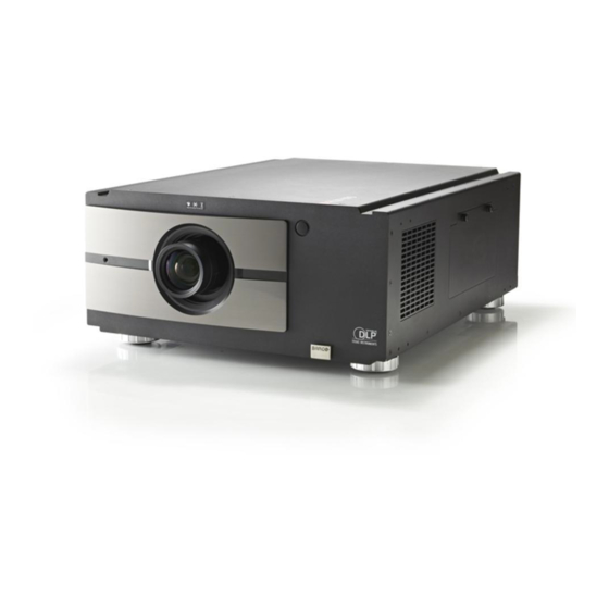
- Page 5 Introduction of the product & Safety precautions BARCO (RLM W8) is compact WUXGA (1920 x 1200 Widescreen Ultra Extended Graphics ), and 3-Chip DLP high-definition images projector. It shares a common Array mechanical, electrical, and optical platform. BARCO (RLM W8) is designed with 0.67” DMD...
- Page 6 Caution: *The projection lens surface has a special coating. 1. Do not use abrasive cleaners and detergents or solvents on the surface. 2. To prevent discoloration or fading, avoid getting cleaner on the projector case C). Cleaning the Main Unit 1.
- Page 7 The interval is depending on the smoke density. Dust clogs at the filter will prevent the projector from drawing cool air to lower the internal temperature. This could lead to overheating and cause the projector to malfunction or become damaged. Use a vacuum cleaner to clean the ventilation slots.
- Page 8 Step2: Remove the dirty filter; you can clean it directly using water. Leave it to dry before replacing it for further use. If the filter is broken or greasy, please replace it by a new one. (Filter Part nr: R9899704). Take out the filter and clean it Step3: Insert the clean filter.
- Page 9 Step4: Reattach the filter cover and tighten the two screws. Close the filter cover Then, fasten the two screws - 9 -...
- Page 10 E). Lamp Replacement The lifecycle of ordinary projection lamp typically lasts for 1500 hours before requiring replacement (different lamp configurations will affect lamp life). From the OSD Menu, you can go to LAMPS Lamp1 or 2 Run Time to check how long a lamp has been used. You should also replace the lamp when the projected image gets noticeably darker.
- Page 11 Step3: Use screwdriver to loosen the screws as shown in the illustration. Loosen the 2 screws Step4: Grasp the metal rod on the lamp cover and pull the lamp out. Pull the two Lamps Step5: Insert the new lamp in the direction shown in the illustration into the lamp assembly;...
- Page 12 Step6: Replace the lamp cover and firmly secure the two screws on the lamp cover. Tightly lock the two screws Step7: Reconnect power to the projector and reset the lamp usage timer. Refer to OSD Menu description Service Lamp1, 2 Run Time. - 12 -...
- Page 13 2. Compliance of Safe Repair Be sure to read this Service Manual before providing services. In the projector, full consideration is taken to ensure the safety for a fire, electric shock, injury, harmful radiation, and substance. Therefore, observe the notice described in this Service Manual so that the safety is kept when providing services.
-
Page 14: Technical Specification
Technical Specification Technical Specification Feature Product Name BARCO RLM W8 Dimensions 670(L) x 517(W) x 247(H) Weight < 26 DMD Tech. TI DLP WUXGA 0.67" 3- Chip DC3 DMD Resolution WUXGA (1920 x 1200) Lamp 330 x 2 UHP Brightness... - Page 15 6. Composite (Video)- 1 RCA x 1 7. RS-232C IN x 1 8. 12V TRIGGER x 2 9. IR ext. x 1 10.10/100 BASE-T (RJ-45) x 1 11. SDI IN & SDI OUT 1. RS-232C (D-sub 9 pins connector) Communication/Control Terminals (38400KB) 2.
- Page 16 - 16 -...
-
Page 17: System Flow Chart
Troubleshooting & Error Code System Flow chart System status Lamp Ignition - 17 -... - Page 18 - 18 -...
- Page 19 LED Status The table for the 3 LED indicators as below: Status Blue Green (Stan (Power) (Issue) dby) 1. Standby Repeat Repeat Lamp is approaching end of life 3. Cooling / Warm up Repeat 4. Power on / Normal 5. Lamp fail Repeat 6.
- Page 20 Error Code Description list Barco RLM W8 error message No. Error Message Led status Description ErrMsgOverTempInlet: Inlet (Ti) sensor over temperature (53 C) ErrMsgOverTempDMD: DMD(Tc) sensor over temperature(69 C) ErrMsgOverTempLamp1: Lamp 1 over temperature ErrMsgOverTempLamp2: Lamp 2 over temperature ErrMsgOverTempBallast1:...
- Page 21 ErrMsgFan11RotateError: Fan 11 rotation error ErrMsgFan12RotateError: Fan 12 rotation error ErrMsgLamp2LitFail: Lamp 2 shut down while system is working ErrMsgBallast2UartError: Ballast 2 UART communication failure ErrMsgGtInletTp: Reserved ErrMsgGtDmdTp: Reserved ErrMsgInletTempSensorFail: Inlet(Ti) temperature sensor reading failure (possibly the sensor not connected) ErrMsgDMDTempSensorFail: DMD(Tc) temperature sensor reading failure (possibly the sensor not connected) ErrMsgGeoSystemFail...
- Page 22 As all above Led display and error code, they will be checked in the Error Mode when system gets error or problem. When there are two conditions as below appearing, you must enter Error Mode. 1. Lamp Extinguish 2. After system light “Red” Led, then it will enter Error Mode once system get error message again. (Ex: When Lamp A light “Red”...
- Page 23 J7: Inlet (Ti) sensor J11: DMD (Tc) sensor J21: Lamp A BALLAST BD LAMP J24: Lamp B - 23 -...
-
Page 24: Fan Status
FAN Status Fan No. Function Type CN - BD Connect FAN 1 Power Fan A CN9801 FAN 2 Power Fan B CN9802 CNF1 - FAN A BD FAN 3 R/G DMD Fan CN9803 FAN 5 Prism Cooling Fan CN9804 FAN 4 B DMD Fan CN9806 FAN 6... - Page 25 RS-232 command of Fans Control statement as below: Op fan1~ fan12 = x , where x is the value about the fan speed, it can be setting Op fan1~fan12 ? , it can be get fan speed Op fan.all ? , it can be get all the fan speed.
- Page 26 Please follow below three kinds of error debugging to get error code: Use RS-232 command to get error code for debugging, please kindly refer to Page 45 (RS-232 Communication) for set-up and debugging. Use web browser (RJ-45) to get error code for debugging. The web browser can be used to check the error code and root cause of the problem.
-
Page 27: Timing Chart
Timing Chart Supported Signal Timings (DVI) Frame Signal Type Resolution rate 640x480 59.94 640x480 74.99 640x480 800x600 60.32 800x600 800x600 85.06 848x480 47.95 848x480 59.94 1024x768 1024x768 75.03 1024x768 85.03 1280x720 47.95 1280x1024 60.02 1280x1024 75.02 1280x1024 85.02 1600x1200 1920x1080 47.95 1680x1050 59.94... - Page 28 480i 59.94 576i EDTV 480p 59.94 576p HDTV 1035i 1080i 1080i (Aus) 1080i 59.94 1080i 720p 720p 59.94 720p 1080p 23.98 1080p 1080p 1080p 29.97 1080p 1080p 1080p 59.94 1080p - 28 -...
- Page 29 Timing name Freq. Freq. Clock H period H display H Sync H backp V Total V display V Sync V backp H(KHz) V(Hz) (M Hz) 640*480-60 31.47 59.93 25.175 640*480-75 37.5 31.5 640*480-85 43.27 85.01 800*600-60 37.88 60.32 1056 800*600-75 46.88 49.5 1056...
- Page 30 1920X1200 61.816 49.93 158.25 2560 1920 1238 1200 1400X1050 65.517 59.98 121.75 1864 1400 1089 1050 1035i 33.75 74.25 2200 1920 1080i 28.13 74.25 2640 1920 1080i (Aus ) 31.25 2304 1920 1080i 33.75 59.94 74.176 2200 1920 1080i 33.75 74.25 2200 1920...
-
Page 31: Remote Control Use
0x06F9. The next 16 are the key data (8 bits) followed by the complement of the key data. A key held down will generate a repeat pulse only. Table : Barco IR Codes & Keynames Code 1 Code 2... - Page 32 Table : Barco IR Codes & Keynames Code 1 Code 2 RS232 Keyname Remote Description Button 0x09 0xB9 power.off Turn power off. menu 0x15 0xBA Bring up or cancel menu display. MENU enter 0x17 0xBB Keypad enter. ENTER 0x18 0xBC cur.down...
- Page 33 Table : Barco IR Codes & Keynames Code 1 Code 2 RS232 Keyname Remote Description Button 0-16 0x8D 0xCD src.3 Switch the active source to source 3. src.4 0-17 0x8E 0xCE Switch the active source to source 4. src.5 0-18...
- Page 34 For the included remote control, the following is required: • The projector and the remote shall be designed together to have a 40 feet range from the front of the projector and a 20 feet range from the top. • The dispersion angle from the IR emitter(s) shall be at least 15 degrees.
- Page 35 Figure 1: IR Remote Control Layout For the projector IR interface, the following is required: • The projector and the remote shall be designed together to have a minimum 40 feet range from the front of the projector and a minimum 20 feet range from the top. •...
- Page 36 Figure 2: IR Reception Angles - 36 -...
-
Page 37: Remote Control Installation
Remote Control Installation - 37 -... -
Page 38: Software Download Process
Software Download Process Projector firmware Download procedures 1. Firmware downloads procedure: 1-1. Connect the AC power of the projector and have the projector in standby mode. 1-2. Connect the RS-232 cable between the projector and the PC. 1-3. Open the Firmware Upgrade Tool accompanied with the firmware release. 1-4. - Page 39 1-7. Click “Upgrade SW” to start the firmware upgrades process. Prior to the firmware upgrade process, you will be prompted with a warning dialog box for confirmation and click “Yes” to proceed the firmware upgrade process. 1-8. The firmware upgrade process indicator of Micro-Control board (The 1 part of this firmware upgrade process) will be shown as follows, 1-9.
- Page 40 1-10. Depending on the file size of the firmware, it may take about 12 ~ 25 minutes before the firmware upgrading can be finished. The following dialog box will be shown after finishing the firmware upgrade process. Click “OK” button and “Exit” from the menu to exit from the whole firmware upgrade process.
- Page 41 2-4. Input the command “op dlw2 = 1” on the terminal 2-5. Close and Exit the terminal program. 2-6. Activate the sxW2 firmware Updater program for the firmware upgrade of sxW2 chip. And select “UART” in the “Targets on” - 41 -...
- Page 42 2-7. Click “Search” button, the available COM port (likes COM:1) will be listed after searching and shown as follows 2-8. Click on the available COM port (e.g. COM: 1 in this example) and select the target firmware (Image File) by clicking the “Browse …” button. 2-9.
- Page 43 3-4. Key in the projector IP on the web browser (the recommended web browser is IE 6.0 or later version, the default IP is 192.168.0.100) to see the embedded webpage. The IP can be accessed via the RS command “op net.ipaddr ?” with a terminal program. 3-5.
- Page 44 3-6. Key in the IP address and followed by “/firmwareUpdate.htm” on the URL box as below to activate the firmware update procedure http://192.168.0.100/firmwareUpdate.htm And click the “Update” button to start the firmware upgrade process. 3-7. The following message will be shown on the display, click “Continue” button to proceed 3-8.
- Page 45 Browse 3-9. Wait until the firmware upgrade process finished. Browse 3-10. The following message will be shown after the firmware upgrade procedure. Just press the “Re Login” button to finish the whole firmware upgrade process of RJ-45 module. - 45 -...
- Page 46 3-11. RJ-45 Test procedures Key in your Projector IP to web browser Information - 46 -...
- Page 47 4. Barco RLM W6/W8 Ballast Firmware upgrade procedure Ballast Firmware upgrade procedure: 1. Before proceeding the following ballast firmware upgrade procedure, please download and install Osram Unishape tool (OsramFlashX) from Osram Website. 2. Connect the AC power of the projector and have the projector in standby mode.
- Page 48 8. Press “Browse” button and then locate and select the new ballast firmware to be flashed. 9. Press “Program” button to start the ballast firmware update. While the firmware update process is proceeding, you will see a progress indicator as follows. 10.
- Page 49 11. Switch off the AC power of the projector. 12. Repeat the above steps #2 ~ #11 for the firmware upgrade of the other ballast and in step #6, please input the command “op dlba2” to specify ballast2 as the target ballast to be updated. The other steps are the same.
- Page 50 After finishing downloading all software in projector, please go to OSD to check your revision confirmation or go to RS-232 to command for confirmation. (A). OSD (B). RS-232 Please key in “op sw.ver ?” And, you can get all software revision. Or, please key in “op soft.version ?”...
-
Page 51: System Operation Commands
RS-232 Communication RS-232 Operation Executive Command Interface and Requirements The RS-232 Commands use only ASCII characters which can be entered using a typical terminal emulator like Windows HyperTerminal with the following setting: Bits per second: 38400 Data bits: 8 Parity: None Stop bits: 1 Flow control: None Note that each input character will be echoed on the terminal by MCU and there is no need to set the... - Page 52 Operation Commands Values Execute (none) Performs an action such as a reset. Motor operation command: For motor control like lens shift, focus and zoom, the parameters “+” and “-” are defined as follows. Command item command System Action focus + => Focus Near, - =>...
- Page 53 Input: op auto.img [CR] Response: OP AUTO.IMG The list of valid operation commands for Barco RLM W8 is shown in below Table. Barco RLM W8 Operation Commands Command Operation Commands Values Notes Item input.sel 0 = HDMI 1 Note1; Note3...
- Page 54 Barco RLM W8 Operation Commands Command Operation Commands Values Notes Item saturat = ? + - 0 - 200 Note2; Note4 tint = ? + - 0 - 200 Note2; Note4 sharp = ? + - 0 - 200 Note2...
- Page 55 Barco RLM W8 Operation Commands Command Operation Commands Values Notes Item zoom 0 = Off Note2; Note6 1 = Crop 2 = Zoom pip.sel 1 = HDMI 1 Note1; 2 = HDMI 2 Note9; 3 = RGB D-15 Please refer to appendix 1...
- Page 56 Barco RLM W8 Operation Commands Command Operation Commands Values Notes Item ceil.mode 0 = floor Note1 1 = ceiling zoomio + = Zoom out Motor command; - = Zoom in Note1 focus + = Focus Near Motor command; - = Focus Far Note1 vert.offset...
- Page 57 Barco RLM W8 Operation Commands Command Operation Commands Values Notes Item 5-10a Lens.center (execute) Note1 5-11 h.keystone = ? + - -350~+350 Note1; Note15 5-12 v.keystone = ? + - -200~+200 Note1; Note15 -20~ +20(in ¼∘unit) 5-13 warp.rotat = ? + -...
- Page 58 Barco RLM W8 Operation Commands Command Operation Commands Values Notes Item 5-28 scen.blk.left = ? + - 0 ~ 32 Note1 ; Note 17 multiple scen.blk.right of 4;the adjustable range and 4-multiple restrictions are per Geo Semi’specification. 5-29 scen.red = ? + -...
- Page 59 Barco RLM W8 Operation Commands Command Operation Commands Values Notes Item 6-11 btn.1 0 = HDMI 1 1 = HDMI 2 2 = RGB D-15 3 = YUV 1 4 = RGBHV/YUV2 5 = Composite Video 6 = S-Video 7 = RGB-S...
- Page 60 Barco RLM W8 Operation Commands Command Operation Commands Values Notes Item 6-14 btn.4 0 = HDMI 1 1 = HDMI 2 2 = RGB D-15 3 = YUV 1 4 = RGBHV/YUV2 5 = Composite Video 6 = S-Video 7 = RGB-S...
- Page 61 Barco RLM W8 Operation Commands Command Operation Commands Values Notes Item 6-17 trig.2 0 = 5:4 Note1 1 = 4:3 2 = 16:10 3 = 16:9 4 = 1.88 5 = 2.35 6 = Letterbox 7 = Native 8 = Unscaled...
- Page 62 Barco RLM W8 Operation Commands Command Operation Commands Values Notes Item pip.src 0 = Off Note1 1 = HDMI 1 2 = HDMI 2 3 = RGB D-15 4 = YUV 1 5 = RGBHV/YUV2 6 = Composite Video 7 = S-Video...
- Page 63 Barco RLM W8 Operation Commands Command Operation Commands Values Notes Item 8-12 CS_cust_My 000 ~ 999 P7 Command; Note1 8-13 CS_cust_Yx 000 ~ 999 P7 Command; Note1 8-14 CS_cust_Yy 000 ~ 999 P7 Command; Note1 picture.mute 0 = Off 1 = On power.on...
- Page 64 Barco RLM W8 Operation Commands Command Operation Commands Values Notes Item 0=ErrMsgOverTempInlet: errcode 1=ErrMsgOverTempDMD: 2=ErrMsgOverTempLamp1: 3=ErrMsgOverTempLamp2: 4=ErrMsgOverTempBallast1: 5=ErrMsgOverTempBallast2: 6=ErrMsgFanInitError: 7=ErrMsgFan1RotateError: 8=ErrMsgFan2RotateError: 9=ErrMsgFan3RotateError: 10=ErrMsgFan4RotateError: 11=ErrMsgFan5RotateError: 12=ErrMsgFan6RotateError: 13=ErrMsgFan7RotateError: 14=ErrMsgFan8RotateError: 15=ErrMsgDMDInitFail: 16=ErrMsgLampInitFail: 17=ErrMsgLampLitFail: 18=ErrMsgBallastUartError: 19=ErrMsgExGpioFail: 20=ErrMsgInterLockOpen: 21=ErrMsgGF9450NoResponse: 22=ErrMsgSystemI2cFail: 23=ErrMsgSoftwareI2cFail: 24=ErrMsgEepromFail: 25=ErrMsgEdidFail: 26=ErrMsgEepVersionFail: 27=ErrMsgRstGennum:...
- Page 65 Note9: pip.sel can NOT be set to 0. Note10: Not applicable when pip is off. Note11: Not applicable when lamp is cooling. Note12: Not applicable when eco.net.pow is on. Note13: Only MCU version number will be read back in standby mode. Note14: Not applicable when the internal pattern is displayed.
- Page 66 Appendix 1: Main Select RGBHV / Composite HDMI 1 HDMI 2 RGB D-15 YUV 1 S-Video RGB-S SDI/HDSDI/3G YUV 2 Video HDMI 1 HDMI 2 RGB D-15 YUV 1 RGBHV / YUV 2 Select Composite Video S-Video RGB-S SDI/HDSDI/3G Source Available Appendix 2: Input Format: 640x480_75Hz_VGA:...
- Page 67 Appendix 3: The allowable combinations of warp, blanking and ScenergiX were summarized as the following table X indicates a not-allowed combination OK indicates a allowed combination - 67 -...
- Page 68 Block Diagram All Function - 68 -...
-
Page 69: Power Function
Power Function Dual Ballast (330W x 2) (CN102, Q106) - 69 -... - Page 70 Replacing Procedures 1. Top cover disassembly 1. Loosen the 14 pcs M4*6 screws. 2. Open the top cover and take off the top cover. - 70 -...
-
Page 71: Board Location
Board Location - 71 -... - Page 72 2. Exchange Motor board 1. Unplug the 7 pcs connectors on the motor board. 2. Loosen the 4 pcs M3*6 screws then you can exchange motor board. - 72 -...
- Page 73 3. Exchange Fan A / Fan B / Fan C board 1. Loosen each 2 pcs M3*6 screws then you can exchange Fan A / Fan B / Fan C board. - 73 -...
- Page 74 4. Exchange Micro control board / Video board / W2 board / RJ-45 board / Keypad board / IR board 1. Loosen 7 screws then take off the cover bracket. 2. Open the cover of control module and take off it. - 74 -...
- Page 75 3. Loosen 4 pcs M4*6 screws on the right side of back cover. 4. Loosen 3 pcs M4*6 screws on the terminal side of back cover. - 75 -...
- Page 76 5. Loosen 4 pcs M4*6 screws on the left side of back cover. 錯誤! 6. Loosen 2 pcs long hex-screws on the AC power of back cover and 2 pcs M4*6 screws on the bottom of back cover. - 76 -...
- Page 77 7. Loosen 1 pc M4*6 screw on the control module. 8. Unplug the 2 pcs connectors from back cover, and then tear down the back cover. - 77 -...
- Page 78 9. Pull the rear cover and take off it. 10. Loosen 1 pc M3*6 screw on the back cover, and then tear down the back IR board. - 78 -...
- Page 79 11. Loosen 4 pcs M3*6 screws on the back cover, and then tear down the Keypad board. 12. Unplug the 3 pcs connectors on the left side of W2 board. - 79 -...
- Page 80 13. Unplug the 3 pcs connectors on the right side of W2 board. 14. Unplug the 8 pcs connectors on the right side of Micro control board. - 80 -...
- Page 81 15. Unplug the 7 pcs connector on the left side of Micro control board. 16. Unplug the 1 pc connector on the video board. - 81 -...
- Page 82 17. Loosen the 16 pcs screws on the rear cover. 18. Pull the whole control module. - 82 -...
- Page 83 19. Loosen the 3 pcs M3*6 screws on the Micro control board. 20. Disconnect the left connector under Micro control board. - 83 -...
- Page 84 21. Disconnect the right connector under Micro control board. 22. Pull the Micro control board. - 84 -...
- Page 85 23. Unplug the connector and loosen 1 pc M3*6 screws on the RJ-45 board. 24. Loosen 2 pcs M3*6 screws on the bracket. - 85 -...
- Page 86 25. Strip down the bracket from control module. 26. Loosen the 7 pcs M3*6 screws on the video board. - 86 -...
- Page 87 27. Strip down the video board. 28. Loosen the 4 pcs M3*6 screws on the W2 board. - 87 -...
- Page 88 29. Strip down the W2 board. - 88 -...
- Page 89 5. Exchange ballast board / power board 1. Remove the 1 pc M3*6 screws on the bracket. 2. Tear down and take off the bracket. 3. Loosen the 4 pcs M4*6 screws on right of right side cover of projector. - 89 -...
- Page 90 4. Loosen the 4 pcs M4*6 screws on bottom of right side cover of projector. 5. Loosen the 2 pcs M3*6 screws on surface of power module. 6. Loosen the other 3 pcs M3*6 screws on surface of power module. - 90 -...
- Page 91 7. Loosen the 1 pc M3*6 screws on top right root of power module. 8. Loosen the 1 pc M3*6 screw on top left root of power module. Loosen the 1 pc M3*6 screw on down left root of power module. - 91 -...
- Page 92 10. Loosen the 1 pc M3*6 screw on down right root of power module. 11. Unplug the 2 pcs lamp high-voltage connectors from power module. 12. Loosen the 4 pcs M3*6 screws on side of power module. - 92 -...
- Page 93 13. Open the top cover of power module upward. 14. Be careful to pull the wire from indentation of power module. 15. Unplug the 8 pcs M3*6 screws and tear down the 2 pcs ballasts. - 93 -...
- Page 94 16. Loosen the 3 pcs M3*6 screws on the top of power board. 17. Loosen the 3 pcs M3*6 screws on the down of power board. 18. Tear down power board from power module. - 94 -...
- Page 95 6. Exchange DMD Engine / Integrator System Assembly 1. Loosen the 4 pcs M4*6 screws on the left of left side cover of projector. 2. Loosen the 4 pcs M4*6 screws on the down of left side cover of projector. 3.
- Page 96 4. Loosen 5 pcs φ3*6 screws and take off the bracket. 5. Loosen the 1 pc M3*6 screw near the front of Fan B board. 6. Loosen another 1 pc M3*6 screw near the front of Fan B board. - 96 -...
- Page 97 7. Loosen 1 pc M3*6 screw near the back of Fan B board. 8. Loosen another 1 pc M3*6 screw near the back of Fan B board. 9. Loosen another 1 pc M3*6 screw near the back of Fan B board. - 97 -...
- Page 98 10. Take off the top cover module of air output. 11. Loosen 3 pcs M4*10 screw and take off the bottom cover module of air output. 12. Loosen 1 pc M3*6 screw on bracket of FIP. - 98 -...
- Page 99 13. Loosen another 1 pc M3*6 screw on bracket of FIP. 14. Loosen another 1 pc M3*6screw on bracket of FIP. 15. Loosen 1 pc M3*6 screw on the bracket of Fan 9 & Fan10 board. - 99 -...
- Page 100 16. Take off the bracket of FIP. 17. Loosen 1 pc M3*6 screw on the bracket of Fan 9 & Fan10 board. 18. Loosen 1 pc M3*6 screw on the bracket of Fan 9 & Fan10 board. - 100 -...
- Page 101 19. Take off the bracket of Fan 9 & Fan10 board. 20. Loosen 3 pcs M3*6 screws and take off the bracket of FIP. 21. Loosen 2 pcs M4*10 screws on Lens Mount cover. - 101 -...
- Page 102 22. Loosen 2 pcs M4*10 screws on bottom of Lens Mount cover. 23. Loosen 1 pc M4*8 screws to remove front panel. 24. Push the small front panel from right to left. - 102 -...
- Page 103 25. Tear down the small front panel. 26. Loosen 4 pc M3*6 screws on bottom of front cover, then take off the front cover. - 103 -...
- Page 104 27. Loosen 7 pcs M4*10 screws on the bottom of DMD engine. - 104 -...
- Page 105 28. Tear down the DMD engine. 29. Loosen 1 pc M3*6 screw on the front of Lamp module base. - 105 -...
- Page 106 30. Loosen another 1 pc M3*6 screw on the front of Lamp module base. 31. Loosen 1 pc M3*6 screw on the back of Lamp module base. 32. Loosen another 1 pc M3*6 screw on the back of Lamp module base. - 106 -...
- Page 107 33. Pull the Lamp module base toward left. 34. Loosen the 2 pcs M3*6 screws on the illumination system assembly. 35. Take off and pull the integrator system assembly. - 107 -...
- Page 108 36. Put back relay Lens on illumination base. ** Note: When we take off integrator system assembly, the relay Lens will be adhered to integrator system assembly. Thus, we need to take off relay Lens from integrator system assembly. Then, we must clean any dust, dirt and fingerprint, and put back.
- Page 109 7. Exchange Lamp Module 1. Loosen the 2pcs screws on the left side Lamp cover of projector, then and open the Lamp cover. 2. Loosen the 2pcs screws on the left Lamp, and pull the left Lamp module. 3. Loosen the 2pcs screws on the right Lamp, and pull the right Lamp module.
- Page 110 8. Exchange Projector Filter 1. Loosen the 2pcs screws on the right side filter cover of projector, then and open the Lamp cover. 2. Take out inside filter of projector. - 110 -...
-
Page 111: Fan Location
Fan Location - 111 -... - Page 112 Fan No. Function CN - BD Connect FAN 1 Power Fan A CN9801 FAN 2 Power Fan B CN9802 CNF1 - FAN A BD FAN 3 R/G DMD Fan CN9803 FAN 5 Prism Cooling Fan CN9804 FAN 4 B DMD Fan CN9806 FAN 6 Engine Exhaust Fan...
- Page 113 Wire Clip & Dressing - 113 -...
- Page 114 - 114 -...
- Page 115 - 115 -...
- Page 116 Folding Mirror Adjustment Disassembly the top cover. 2. Check the full-white image where color band is, and slight adjust fixed-nut to remove it. 3. When finish adjusted, add TB1401B glue on the nuts to fix it. - 116 -...
- Page 117 Kit definition & Pictures Projector spare part Part Nr. Parts Description BME RLM W8 LAMP - HOUSING ASSY BME RLM W8 INTEGRATOR ASSY BME RLM W8 DLP ENGINE MOD ASSY BME RLM W8 PWB ASS R FORMATTER BME RLM W8 PWB ASS G FORMATTER BME RLM W8 PWB ASS B FORMATTER BME RLM W8 HORI.
- Page 118 BAG PE 710 * 570 *580 WHT END BLOCK EPE BOTTOM REAR 650 * 243.5 * 185 END BLOCK EPE BOTTOM FRONT 650 * 243.5 * 185 CARTON CRGD PAPER 814*653*364 BME RLD LENS MODIFICATION KIT BME RLM W8 LIGHT SHUTTER - 118 -...
- Page 119 - 119 -...
- Page 120 - 120 -...
- Page 121 - 121 -...
- Page 122 - 122 -...
- Page 123 - 123 -...
- Page 124 - 124 -...
- Page 125 - 125 -...
- Page 126 Please refer to Page 136 ~ Page 141 - 126 -...
-
Page 127: Unpack The Unit
Unpack the unit - 127 -... - Page 128 Carton Lamp Carton inside Out - Dim. 669*157*175 nothing Empty carton inside Carton Out - Dim. 157*165*217 nothing Empty carton inside Carton IN - Dim. Carton inside W6 projector 990*673*400 Out - Dim. 1006*689*432 - 128 -...
- Page 129 1. CD 2. WEEE Sheet 3. Quick Start Guide - 129 -...
- Page 130 Lens part Assembly & Disassembly procedure Task 1: Disassembly the RLD lens Step 1: Disassembly the front cover and motor bracket 2 screws 5 screws - 130 -...
- Page 131 Step 2: Disassembly lens flange and motor cover 3 screws 6 screws 4 screws Step 3: Disassembly motor module 2 screws 4 screws - 131 -...
- Page 132 Just keep projection lens and motor module for HV3C using Task 2: BARCO RLM W Lens. Step 1: Assembly motor bracket Zoom stand-off Focus (Short) stand-off Part A (2 screws) - 132 -...
- Page 133 Step 2: Assembly motor module Focus motor Blue /Red Zoom motor White /Brown Fixed motor module (4 screws) - 133 -...
- Page 134 Step 3: Assembly motor connector and motor cover Connecting Fixed wire with with Part B Cable tie 2pcs Motor wire 2 twists with stand-off Connector hide in cover 2 screws Part C (4 screws) Cable tie - 134 -...
- Page 135 Step 4: Assembly lens Clip Part D (3 screws) Step 5: Assembly Lens cover Part E (2 screws) Fixed bracket insert direction. - 135 -...
- Page 136 Finish photo: - 136 -...
- Page 137 Lens part list Consign Part list Item 3: Stand-off Focus (Tall) x2 Item 2: Stand-off Zoom (Short) x2 Item 1: Bracket Motor x1 Item 4: Screw M3*0.5 x2 - 137 -...
- Page 138 Item 1: Cable motor connector x 1 Item 3: Wire Saddle x1 Item 2: Bracket Connector x1 Item 4: Screw M3*0.5*6 x2 - 138 -...
- Page 139 Item 1: Motor cover x 1 Item 2: Wire saddle x 1 Item 3: Screw M2*0.4 x 4 - 139 -...
- Page 140 Item 1: Clip Lens Assy x 3 -- Item 2: Screw M4*0.7 x 3 - 140 -...
- Page 141 - 141 -...
- Page 142 - 142 -...
- Page 143 Item 2: Packing Box x 1 These are total Projection Lens packing material only for BARCO. BARCO P/N DESCRIPTION R9832740 PROJ LENS FIXED 0.8-1.0 F2.5 R9832741 PROJ LENS FIXED 1.2 F2.5 R9832742 PROJ LENS ZOOM 1.5-1.8 F2.5 G80 R9832743 PROJ LENS ZOOM 1.8-2.25 F/2.5 G100 R9832744 PROJ LENS ZOOM 2.25-3.0 F2.3 G200...
Need help?
Do you have a question about the RLM W8 and is the answer not in the manual?
Questions and answers