Barco RLM W12 User Manual
Rlm w12 projector
Hide thumbs
Also See for RLM W12:
- Service manual (128 pages) ,
- Specifications (3 pages) ,
- Quick start manual (2 pages)

Related Manuals for Barco RLM W12


Summary of Contents for Barco RLM W12
- Page 1 Please read this manual before using this projector RLM W12 USER’S GUIDE User’s Guide...
-
Page 2: Table Of Contents
INDEX Warning, Notices and Safety Instructions Notice Description pertaining to FCC Rules Part 15e: Warning and Safety Instructions Notices you should read prior to the installation of the projector Projector parts and functions Front view Rear view Bottom view Range of effective remote control signal reception Installing batteries in the remote control Quick installation of the projector Throw distance Modes of installation Horizontal and vertical lens shift Installing the projector Connecting the projector to other devices 12V Trigger connection RGB connection RGBs connection IR INPUT connection S-Video/Video connection COMPONENT connection Turning on the projector Changing OSD language Adjusting screen orientation Adjusting the projector lens... - Page 3 Using the remote control OSD Menu Tree OSD Menu Description INPUT IMAGE LAYOUT LAMP ALIGNMENT CONTROL SERVICE Lamp and filter maintenance Lamp replacement Cleaning the filter Simple troubleshooting and definition of the LED indicators Projector specifications...
-
Page 4: Warning, Notices And Safety Instructions
Warning, Notices and Safety Instructions Notice Please write down your projector model number and serial number and keep the information for maintenance purposes in the future. Should the equipment be lost or stolen, the information could also be used for the police report. Model number: Serial number: Please check the accessories that come with the projector with the following list. Should you find any missing accessory, contact your dealer immediately. US specification power cord*1 EU specification power cord*1 China specification power cord*1 Remote control *1 AA battery *2 User's Guide *1 Setup Manual *1 Safety Manual *1 Warranty Card *1 10: WEEE Notification Card *1 11: CD ROM *1 Description pertaining to FCC Rules Part 15e: This device has been tested and found to comply with the limits for a Class A digital device, pursuant to Part 15 of the FCC Rules.These limits are designed to provide reasonable protection against harmful interference in a residential installation. This equipment generates, uses and can radiate radio frequency energy.If not installed and used in accordance with the instructions, may cause harmful interference to radio or television reception.However, there is no guarantee that interference will not occur in a particular installation.If this equipment does cause interference to radio or television reception, which can be determined by turning the equipment off and on, the user is encouraged to try to correct the interference by one or the following measures: • Reorient or relocate the receiving antenna. -
Page 5: Warning And Safety Instructions
Warning, Notices and Safety Instructions For more information, please contact Electronic Industries Alliance (WWW.EIAE. ORG). For information on proper lamp handling, visit WWW.LAMPRECYCLE.ORG. Warning and Safety Instructions Special Care for Laser Beams! Special care should be considered when DLP projectors and high power laser equipment are used in the same room as. Direct or indirect hit of a laser beam on to the projector lens can severely damage the Digital Mirror Devices (DMD™). Sun light Warning Avoid using the RLM W12 in direct sun light. Sun light on the projector lens can severely damage the Digital Mirror Devices (DMD™). Never look into the projector light source directly This equipment contains a high brightness light source and a portion of the light emitted by the projector is ultraviolet light. Never look into AVOID EYE CONTACT TO THE LIGHT the projector light source directly and pay special attention to prevent children from looking into the projector light source as it can damage their eyes. -
Page 6: Carrying The Projector
Warning, Notices and Safety Instructions Cleaning When cleaning the projector, be sure to unplug it from the wall outlet to prevent electric shock. Do not use liquid or aerosol cleaners. Use a dry/damp cloth with excessive moisture removed for cleaning. Be sure to use cleaning cloth designed to clean monitors for the projector to prevent damages to the projector casing due to abrasion. Dampness, smoke, steam, dust, high temperature and direct exposure to sunlight Do not operate the projector in environments where it could be expose to dampness, smoke, steam, dust, high temperature or direct sunlight.For example: bathroom, kitchen, adjacent to washing machine, damp basement rooms, electric heaters or similar environments.Keeping or operating the projector in the above-mentioned environment could lead to discoloration, mold formation, grease or damages to the projector. Ventilation The projector case is designed with slots and openings to remove the heat inside the projector so that it will not overheat and damage the components.Be sure to operate the projector in an environment with ideal ventilation and don't operate it on a sofa, rug or other closed-in environments that could obstruct ventilation. Filter Make sure to clean or replace the filter when it is required to keep the air intake clear of dust, and prevent possible over temperature issue of the projector due to the clog of filter. Please refer to Page 55 for details of filter replacement procedure. Intrusion of foreign objects Be sure to keep all foreign objects away from entering the projector because it could be exposed to hazardous voltages and cause parts to short circuit. This could in turn lead to fire hazard or electric shock.Examples of foreign objects include: cockroach, screws, liquid and... -
Page 7: Notices You Should Read Prior To The Installation Of The Projector
Warning, Notices and Safety Instructions Should you encounter any of the following situation, please unplug your projector from the wall outlet and contact a qualified service personnel for assistance: • Damaged power cord or power plug. • I f a foreign object has fallen into the projector or if you have spilled water or other liquid into the projector. • If the projector has been dropped accidentally or damaged. • I f you experience noticeably poor performance or malfunctioning with the projector despite having followed instructions for normal operation Changing parts Should any part of the projector be damaged, check with your servicing personnel that only manufacturer certified parts were used for replacement. Used of non-certified parts may result in damages to the projector or hazards such as fire or electric shock.After changing parts, be sure to remind the servicing personnel to perform safety inspections to ensure that the projector operates normally. Power cord Don't place the projector where the cord can be walked on. This may result in fraying or damage to the power cord, especially at the plug and the point of connection between the power cord and the projector. Please use the power cord that comes with the projector or the type of power cord specified for the projector (refer to the descriptions printed on the power cord). If you are not sure of the power available at the region you are in, consult your local power company to prevent damages to the projector due to the use of wrong power cord or potential fire hazards due to current overload. Depending on the country and region you are in, the voltage and type of socket of the wall outlet may be different from the projector. If you are unable to fit the power plug into the wall outlet, contact your local dealer and do not remove the extra pin on the power plug to forcibly fit it to the socket at the risk of your own safety. -
Page 8: Do Not Tilt The Projector More Than 15 Degrees
Warning, Notices and Safety Instructions cleaned routinely to prolong the projector's lifecycle. Cleaning of the projector's interior should only be performed by qualified service personnel dispatched by your local dealer and you should not attempt to clean the inside of the projector by yourself. If other light source is directly projected onto the projector screen, the color of the image from the projector will appear to be pale and the image quality will be lower. In addition, your eyes would be more prone to fatigue. Therefore, it is recommended that the projector be installed in places without direct exposure to sunlight or other sources of intense light. The ideal operating temperature range for the projector is between 32°F ~ 104°F (0°C ~ 40°C) The ideal storage temperature range for the projector is between -4°F ~ 104°F (0ºC ~ 40°C) Do not tilt the projector more than 15 degrees. The maximum tilt angle for the projector is 15 degrees. When the projector is tilted more than 15 degrees, it will shorten the life of the projector lamp and may lead to other unpredictable damages. Can’t >15° Can’t >15° Configurations for projector operation at high altitudes When operating the projector at higher altitudes, be sure to manually set the fan mode to "High"... - Page 9 Warning, Notices and Safety Instructions Name and quantity of toxic/hazardous substances/elements contained in the product...
-
Page 10: Projector Parts And Functions
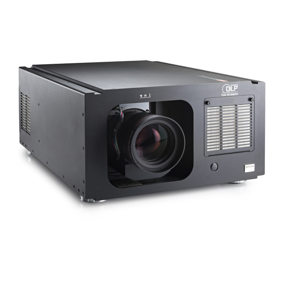
Projector parts and functions Front view Ventilation slot The hot air generated inside the projector is dispersed through the ventilation slot. Make Lens sure the ventilation slot is free from obstruction. Ventilation inlet Adjustable foot The internal cooling fan draws Adjust the height and angle of the cool air from the ventilation inlet projector with the adjustable foot into the projector. Infrared receiver Rear view Power switch I → ON O → OFF Voltage Selector (Default at 110V) Power inlet Projector Keypad Adjustable foot Infrared sensor Adjustable foot MENU... -
Page 11: D Sync In
Projector parts and functions IR ext. S-VIDEO Receives input signal from compatible Niles or Xantech IR Standard S-Video input that connects to DVD players, satellite repeater systems. receiver or Super VHS (S-VHS) VCR. VIDEO 12V TRIGGER Connects to VCR, laser disc players or other (3.5-mm, mini phone jack) component image sources.Also connects to the Offers 12 (+/- 1.5) V of output for 350mA monitor relay composite image synchronized input from RGBS input source. with short circuit protection. YUV1 RS-232 Standard and high definition (480i/480p/ 576i/576p/720p/1080i/1080p) component 9-pin D-sub socket. Connects your PC or input, connects to DVD/HD-DVD/BD player, automatic home theater /control system. HD set-top-box or other SD/HD input source. Also connects to RGB input from RGBS input 10/100 BASE-T source. Connects the projector to your PC via network to enable di- rect control of the projector on your PC. -
Page 12: Bottom View
Projector parts and functions Bottom view Adjustable foot Adjust the height and angle of the projector with the adjustable foot Mounting bracket screw hole These screw holes are used to mount the projector to its designated mounting bracket using 3 M8x15 screws and 3 M8x40 bolts. The dimensions of the screw holes are shown in the image below. M8x15 3 screws M8x40 152.5 3 bolts Ceiling Mount Order Info: 1. R9849999-Ceiling mount 2. R9841260-Short Pulley 400mm to 765mm 3. R9841261-Long Pulley 800mm to 1165mm... -
Page 13: Range Of Effective Remote Control Signal Reception
Projector parts and functions Range of effective remote control signal reception The diagram below illustrates the range of effective remote control signal reception. 40° 40° Note: A void placing the remote control at places of high temperature or humidity as it could cause the remote control to malfunction. Installing batteries in the remote control Remove the cover by Insert two new AA Replace the cover. sliding it in the direction batteries indicated by the arrow. (observe the polarity). Note1: Be sure to insert the batteries in the corresponding orientations to match the polarities. Note2: D o not mix new batteries with used batteries as it would shorten the life of new batteries or cause leakage. Note3: O nly used AA batteries as instructed; do not attempt to insert different types of batteries into the remote control. -
Page 14: Quick Installation Of The Projector
Quick installation of the projector Quick installation of the projector. 1. Orient the projector towards the screen Screen 2. Connect the power cord to the projector Please select the AC POWER SWITCH correct input voltage before removing the VOLTAGE SELECT warnning labe. 12V TRIGGER RGB-S 350mA RS-232 IR ext. - Page 15 Quick installation of the projector 5. Adjusting the projector's angle a. P lease use the adjustable feet to change the angle of the projector in order to achieve the most suitable angle for projection on the screen. b. Adjusting the lens by horizontal and vertical lens shift Method 1: P ress the ENTER button on the remote control to access Lens Control adjustment screen before pressing ENTER once again to access the menu and use the ▼ ▲ buttons to adjust the horizontal or vertical position of the lens. Press ENTER once to Press ENTER once to Press ENTER once to Press ENTER again adjust zoom and focus with Adjust Lines shift with adjust zoom and focus to adjust vertical and cross line cross line shift horizontal lens Enter Enter Enter Enter ...
-
Page 16: Correcting Keystoning Caused By Projection Angle
Quick installation of the projector b. P ress the MENU button on the remote control and choose Alignment Lens Control; then use the ▼ ▲ buttons to adjust the size of the image that is projected onto the screen. Original image size Zoom out Zoom in 7. Correcting keystoning caused by projection angle a. T o adjust horizontal keystoning, press the MENU button on the remote control and choose ALIGNMENT Warp Keystone and use the buttons to adjust the image. b. To adjust vertical keystoning, press the MENU button on the remote control and choose ALIGNMENT Warp Keystone and use the ▼ ▲ buttons to adjust the image. -
Page 17: Throw Distance
Installing the projector Throw distance Throw Distance (TD) = Screen Width (W) x Throw Ratio (TR) Coupled with the available projection lenses, the projector offers the following throw ratios: • R9862000-TLD+ (0.73:1) • R9840775-TLD+ (1.2:1) Note: • R9862010-TLD+ (1.5 - 2.0:1) Projection lenses are optional • R9862020-TLD+ (2.0 - 2.8:1) accessories. Please contact your • R9862030-TLD+ (2.8 - 4.5:1) local dealer to acquire the projection • R9862040-TLD+ (4.5 - 7:5:1) lens that suits your need most. • R9829997-TLD+ (7.5 - 11.2) • R9862005-TLD+ Ultra (1.25-1.6) Modes of installation • I nstall the projector in an environment below 35°C (95°F). The projector should be kept clear from sources of heat and / or ventilation openings of air conditioner. • T he projector should be kept away from devices that emit electromagnetic energy, such as motor and transformer.Common devices that emit electromagnetic energy include slideshow system, speakers, power amplifiers and elevators. -
Page 18: Installing The Projector
Installing the projector Frontal projection - ceiling mode Rear projection - ceiling installation Advantage: d oes not occupy floor space Advantage: t he projector is completely does not draw attention to it. hidden from plain view this setup Eliminates the possibility that usually offers better reduction of someone would accidentally ambient noise. move the projector. Disadvantage: r equires an additional room for installation. Stricter installation Disadvantage: s tricter installation requirements and conditions; requirements and conditions; care should be taken during care should be taken during the installation to ensure the the installation to ensure projector has been securely the projector has been mounted. operation of the securely mounted. -
Page 19: Horizontal And Vertical Lens Shift
Installing the projector Horizontal and vertical lens shift In addition to using the adjustable feet to adjust projection angle, you can also use the Lens Shift function to adjust the projected image. Moving the lens vertically The distance of vertical lens movement is +110% , -70% of half the screen height in both directions.For instance, if you are using a 80" × 50" screen, you will be able to move the image upwards more than 27.5'' or downwards more than 17.5''. This illustration shows normal vertical lens shift without the use of special specification lens or projector. Note:Please make sure the center of lens is retangular to the center of the ccreen. Moving the lens horizontally The distance of horizontal lens movement is 30% of half the screen width in both directions. -
Page 20: Installing The Projector
Installing the projector Connecting the projector to other devices HDMI / DVI connection Signals from image source offer the best projection image quality when sent through HDMI. Therefore, try to use input devices with HDMI output as the source of image. HDMI/DVI input source (BD/HD-DVD/DVD player, HD set-top-box, gaming consoles and so forth) 12V Trigger connection If your home theatre system includes a projector screen, screen cover or other 12V Trigger equipment, please connect such device/equipment to the projector’s 12V Trigger output as illustrated. After you have done so, Your screen will lower automatically whenever you turn on your projector for your convenience. Retractable screen or other 12V TRIGGER RGB-S 12V device... -
Page 21: Rgb Connection
Installing the projector RGB connection Connect your PC or other devices with RGB output to the RGB input connectors on the projector to be used as the source of image input. 12V TRIGGER RGB-S 350mA RS-232 IR ext. S-VIDEO VIDEO YUV 1 Desk Top or Notebook RGB-HV/SOG B/Pb R/Pr HDMI RGBHV / YUV 2 AC MAINS AC POWER SWITCH 100-240 Volts 50/60Hz B/Pb R/Pr B/Pb R/Pr Desk Top or Notebook... -
Page 22: Rgbs Connection
Installing the projector RGBs connection If the source equipment uses composite image synchronized connectors to output RGB, please connect the green, blue and red connectors to the Y, Pb, Pr jacks at the COMPONENT1/SCART inputs and the synchronized output to the VIDEO jack. Synchronize Green Blue Red DVD player or other SCART RGBS input sources RGB-S YUV 1 S-VIDEO VIDEO YUV 1 IR INPUT connection RGB-HV/SOG B/Pb R/Pr If the projector is unable to pick up the IR signals from the remote controle due to distance or HDMI HDMI RGBHV / YUV 2 obstacles (i.e. wall or cabinet doors), you can connect an external IR repeater to the projector’s IR INPUT jack to extend the effective signal reception range. -
Page 23: S-Video/Video Connection
Installing the projector S-Video/Video connection If the image input device offers both S-Video and Video connection, it is recommended that you choose S-Video to obtain better image quality.If both the S-Video and Video inputs are connected to the projector, the projector will prioritize S-Video signal input and image from the Video input will not be played. 12V TRIGGER RGB-S 350mA 10/100 BASE-T RS-232 IR ext. S-VIDEO VIDEO YUV 1 RGB-HV/SOG B/Pb R/Pr HDMI HDMI RGBHV / YUV 2 SDI / HDSDI / 3G DVD player, VCR, satellite receiver, LD and so forth COMPONENT connection Take the 3/5 cabled RGB component video connectors from the source equipment to the... -
Page 24: Turning On The Projector
Installing the projector STEREO DVI Connection IR EMITTER 3D Glasses Connect the STEREO DVI to a stereo 3D source – it is usually a computer with 3D Graphics card, and 3D applications. 3D mode There are few ways to go to the 3D mode • OSD menu: Go to Main Menu “Input > Input Selection”, and select STEREO DVT • Remote control: Press hot key “5” to go to STEREO DVI directly • Network Webpage: Go to “Source/general” > “Source” and select STEREO DVI • RS232 Commands : Use “ Input.sel = 9” to select STEREO DVI 2D mode Please note that OSD menu is not available in 3D mode. The ways to switch back to 2D mode are: • Remote control: Press any of the input key 1-4 will switch back to 2D mode. • Network Webpage: Go to “Source/general” > “Source” and select any other source that are available. • RS232 Commands: Use “ Input.sel = 1-8” to select any other source that are available. Turning on the projector... -
Page 25: Changing Osd Language
Installing the projector Refer to the instructions covered in “ Page 14 : Quick installation of the projector. “. Changing OSD language By factory default, the OSD menu of the projector is displayed in English. If you wish to switch to a different language, you can go to MENU CONTROL Language and choose the language you prefer for the OSD. -
Page 26: Adjusting Screen Orientation
Installing the projector Adjusting screen orientation By default, the projector is configured for “frontal projection - desktop installation”. If you choose to install your projector in other setups, be sure to adjust the screen orientation to achieve the correct projection mode. Front projection - ceiling mode Press MENU ALIGNMENT Ceiling Mode and choose ON; the projector is now configured for “frontal projection - ceiling mode”. Correct Picture canoe c a n o e ... -
Page 27: Adjusting The Projector Lens
Rear projection - desktop installaion Press MENU ALIGNMENT Rear Projection and choose ON; the projector is now configured for “rear projection - desktop installation”. Correct Picture canoe Rear projection - ceiling mode Press MENU ALIGNMENT Rear Projection and choose ON; press MENU once more ALIGNMENT Ceiling Mode and choose ON Correct Picture canoe Adjusting the projector lens Projector lens adjustment includes focus, zoom, horizontal/vertical image shift. Please refer to Page 15 : “5. Adjusting the projector’s angle”., “6.Adjusting focus and zoom.”. and “7. Correcting keystoning caused by projection angle”. for detailed instructions. -
Page 28: Using The Remote Control
Using the remote control 4 = YUV1 5 = Stereo DVI You can configure the input source that corresponds to each button in INPUT the OSD Menu. To do so: When press MENU > CONTROL > Button 1~5; use the ▼ ▲ buttons to choose from diffferent sources of input. You can choose from: HDMI 1,HDMI 2,RGB D-15,YUV 1,RGBHV/YUV 2,Composite Video,S-Video 4 and RGB-S. For example, if you have configured as RGB D-15 in the OSD Menu, when you press ASPECT MENU on the remote control, the projector will RATIO display the image from RGB D-15. AUTO IMAGE ▼▲▲▲ PAUSE TEXT Use these buttons to make your SHARPN selection or configure, adjust configuration or toggle between PHASE COLOR TINT image displays. ENTER SWAP ADDRESS Use this button to select items in the... - Page 29 Using the remote control PAUSE will function normally; make the image appear more pressing any other buttons will magenta, while increasing this not access the OSD Menu. setting will make the image appear more green. AUTO IMAGE PIP This button is used to Resync the Use this button to display or image; when the image signal disable PIP. becomes unstable or image SWAP SWAP quality deteriorates simply press Use this button to switch the this button and the projector will sources of image PIP display. automatically adjust the screen ADDRESS dimension, phase, timing and so ADDRESS *Only 2 addresses are possible* forth.(The adjustments also apply Press and hold the ENTER buton to PIP input). and press this button until the CONTRAST remote control panel flashes once Adjust the level of white in the (approximately 5 seconds) to image to increase or decrease change the receiving address of image contrast. the remote control. If you use one BRIGHTNESS remote control to operate two...
-
Page 30: Osd Menu Tree
OSD Menu description OSD Menu Tree Off Zoom Crop OSD Menu Zoom HDMI1 Tree HDMI2 RGB D-15(RGB-HV/ SOG)YUV1(RGB-S) YUV2(RGBHV/YUV2) HDMI1 Main Select Composite Video(Video) HDMI2 S-Video RGB D-15(RGB-HV/SOG) RGB-S YUV1(RGB-S) SDI/HDSDI/3G RGBHV/YUV2 Input Selection STEREO DVI Composite Video(Video) S-Video HDMI1 LAYOUT RGB-S HDMI2 SDI/HDSDI/3G RGB D-15(RGB-HV/ SOG)YUV1(RGB-S) STEREO DVI PIP Select YUV2(RGBHV/YUV2) Auto Composite Video(Video) -
Page 31: Osd Menu Description
OSD Menu description Top Left Rear Projection Top Right Botton Left Menu Position Ceiling Mode Botton Right Center Zoom/Focus Lens Control Shift Start Up Logo On Dynamic Contrast Off Start Up Chime 1.8 2.0 2.2 Gamma HDMI1 Button 1 2.35 2.5 HDMI2 On (1~12 Pattern) RGB D-15(RGB-HV/ Button 2 Internal Patterns Off (0 off) SOG)YUV1(RGB-S) Button 3 YUV2(RGBHV/YUV2) Native, EBU, SMPTE Color Space Composite Video(Video) Custom Button 4 S-Video RGB-S Control Execute Lens To... -
Page 32: Osd Description
OSD Menu description OSD Description 1. Press the MENU button on the remote control or on the back of the projector to bring up the OSD Menu. 2. You will see seven functional menus (Input, Image, Layout, Lamp, Alignment, Control and Service). Press ◄ or ► to select the desired sub menu. 3. Press ▲ or ▼ to select the desired sub menu. 4. Your current selection in each of the sub menu will be displayed in yellow text and highlighted in blue. Press ◄ or ► to access the configuration for the selected item or press ENTER to go to another sub menu. 5. Press MENU to return to the previous menu. 6. From the main menu, press MENU to close the OSD Menu. INPUT Input Selection Use this function to specify the source of image connected to the rear of the projector. For instance, if you have connected your PC as the video input source, you can choose RGB D-15(RGB-HV/SOG) to be the input for image projection. Options of input available on the projector include: HDMI1, HDMI2, RGB D-15(RGB-HV/ SOG), YUV1(RGB-S), YUV2(RGBHV/YUV2), Composite Video(Video), S-Video, RGB-S, SDI/HDSDI/3G. STEREO DVI. Input Locking Use this function to specify the frequency of the image input signal. You can let the projector determine the optimal projection frequency or force the projector to project image at the... -
Page 33: Image
OSD Menu description frequency in order to achieve optimal image output. If the frequency of the input signal falls between 24~31Hz, the projector will automatically double the vertical refresh frequency. If the frequency of the input signal falls between 31~48Hz or exceeds 62Hz, the projector will automatically set the frequency to 60Hz. 50Hz • Choose this option to set image output frequency at 50Hz. 60Hz • Choose this option to set image output frequency at 60Hz. Note: I f you enable PIP, the projector will automatically synchronize the frequency of the PIP input signal with the main input signal. Auto Power Off The default value is OFF. If you set it to ON, the projector will automatically shut down after 20 minutes without input signal. Auto Power ON The default value is Off.If you set it to ON, the projector will automatically start up when it is connected to AC power. If you plug the projector’s power cord into an AC socket with a switch, you can use this function to start up the projector using the socket’s switch instead of the remote. If you do not need this function, please set it to Off. No Signal Use this function to specify the content or color to be displayed on the blank screen when no input signal is available.You can choose from Logo, Blue, Black, White.The default value is Logo. Video Standard Different countries may use different video signal formats. Please choose the video standard in your area. Auto • This is the default value.The projector will automatically determine the video standard used in your area. -
Page 34: Auto Image Adjust
OSD Menu description Auto Image Adjust You can configure the Auto Image Adjust function to one of the following three modes: =NEVER • Auto =When not done before(or when done first time) • Always =When new source selected or new source connected. • For more information on Auto Image Adjust, refer to “ Page 34 : Auto Image Adjust “. IMAGE Contrast Use to adjust the contrast of the projected image.You can connect the projector to an external image source to display an image resembling the one shown below for adjustment. It is recommended that you adjust the projected image according to the results shown below so that the brightness of the spectrum remains constant throughout and achieve maximum contrast between black and white. The following image illustrates the results of direct contrast adjustment using a random image: Original image Enhanced contrast Lowered contrast... - Page 35 OSD Menu description Brightness Use to adjust the brightness of the projected image.You can connect the projector to an external image source to display an image resembling the one shown (PLUGE, Picture Line- Up Generation Equipment) for adjustment. Although there are numerous versions of PLUGE image, they are typically comprised of blocks of black, white and gray on top of a black background. It is recommended that you adjust the image to the following status: • T he darkest black bar of the image should disappear into the background. • The dark gray area should be barely visible. • The light gray area should be clearly visible. • T he white area should appear real and mellow. • T he image should only display black, gray and white (with no other colors). Above Black Contrast, Brightness, Saturation and Tint are interrelated options that Below Black affect one another; when you adjust one of them, you might have to fine tune other settings to get the best projection results. The following image illustrates the results of direct brightness adjustment using a random image: Original image Enhanced brightness Reduced brightness Saturation Use to adjust the saturation of the projected image.If the color of the projected image...
- Page 36 OSD Menu description Tint Use to adjust the tint (balance between magenta and green) of the projected image. Lowering the value will make the image appear redder; increasing the value will make the image appear greener. Original image Enhanced tint Reduced tint Sharpness The adjustment of sharpness primarily changes the value of high frequency detail. You can connect the projector to an external image source to display an image resembling the one shown below to adjust the image sharpness. The following image illustrates the results of direct sharpness adjustment us- ing a random image: Original image Enhancedsharpness Reduced sharpness...
-
Page 37: Noise Reduction
OSD Menu description Noise Reduction Use to adjust the noise of the projected image. This function is suitable for the elimination of image noise from interleaving SD input.Generally speaking, reducing image noise will lower the value of high frequency detail and make the image appear more mellow. → noise reduction Color Temperature You can choose from 3200K, 5400K, 6500K, 9300K and Native. Color temperature refers to the change in light color under different energies that is perceived by the naked eye.The change of color temperature from low to high for visible light goes from orange red white blue The projector’s default color temperature is set at 6500K and it is suitable for most situations. As color temperature rises, the image will appear to be more blue; as it decreases, the image will appear redder.When you choose “Native”, the projector will disable the white adjustment function of the input device. Input Balance Regardless of the change in ambient light, the human eye is equipped with an automatic adjustment mechanism that makes a white object appears white and black object black. However, since no machine has such an incredible innate feature, you may need to make certain adjustments to the projector’s settings when the ambient light changes so that the image will appear closer to the actual colors. input White balance signal adjust the point where CUT off the point where saturation for RGB is reached is reached needs to be same... -
Page 38: Aspect Ratio
OSD Menu description Gain This refers to the control of color imbalance in the brighter areas of the projected image.It is recommended that you use an external test image with many areas of white (i.e. an image of 80IRE-window). If you notice minimal amount of red, green or blue in the gray areas, lower the gain of the corresponding color accordingly.This function is used to increase or decrease the range of color input for the entire image. Generally speaking, as gain increases, the contrast of the image will become lower.By increasing the offset, the image brightness will become lower. Black Balance Offset • T his function involves the adjustment of the following red, green and blue offsets. The text itself is decorative. Red Offset • Press to adjust the offset of red in dark scales. Green Offset • Press to adjust the offset of green in dark scales. Blue Offset • Press to adjust the offset of blue in dark scales. White Balance • This function involves the adjustment of the following red, green and blue gains. The text itself is decorative. Red Gain • Press to adjust the gain of red in bright scales. Green Gain •... - Page 39 OSD Menu description Native input Output aspect ratio Output aspect ratio Output aspect ratio 16:9 Output aspect ratio Output aspect ratio Output aspect ratio Output aspect ratio 1.88 2.35 Letterbox Native Cropped portion of the image Note : that when used for commercial purposes, including: projection of image in movie theatres, hotels, cafeteria and other public venues, compression or extension of image achieved through the change of aspect ratio may constitute copyright infringement to the rightful owner of the image. Please do so at your own discretion. Timings H Total •...
-
Page 40: Auto Image
OSD Menu description Native picture Skewed left Skewed right H Phase • Use to adjust the projected image’s phase. U se this function to adjust the phase of pixel sampling clock (relative to input signal). Should the image still flicker or show noise (i.e. edges on texts) after optimization, adjust phase accordingly. V Start • Use to adjust the projected image’s vertical position. I f the projected image is not at the center of the screen (i.e. shifted up or down) and ends up being cropped, use this function to adjust the image’s vertical position.The following image is an example of test image from an external signal source: Skewed down Skewed Up Native picture I t is recommended that when adjusting the image, the horizontal total should be adjusted before the horizontal phase. However, if the image still flickers even after you have adjusted both, try lowering the image noise. Auto Image When Auto Image was selected in the OSD menu, press ENTER to execute the automatic image adjustment function. By executing this function, the projector will resync the image. Use this function when the image source is unstable or when you notice deterioration in image quality and the projector will automatically adjust the image size, phase and timing. (The adjustment also applies to PIP input source). -
Page 41: Layout
OSD Menu description LAYOUT Zoom Due to the fact that some consumers may still be using older television systems, some TV programs may not display the edges of the image. Use this function to hide the image edge by choosing one of the following three options: • Setting it to off makes no change to the projected image. Crop • S etting it to "Crop" will add two "masks" equivalent to 3% of horizontal resolution on either side of the image and two similar masks above and below the projected image. Zoom • Y ou can use this function to enlarge the image's horizontal resolution over the 106% of the default aspect ratio. Any portion that exceeds the original image will be cropped. When you set aspect ratio to "Native", be sure to set Zoom to "Off" or "Crop". Crop Zoom 16:10 2.35 Main Select When you want to project PIP image, use this function to specify the image source for the PIP image. This function is identical to Input Selection; for more information, please refer to " Page 32 : Input Selection ". -
Page 42: Pip Select
OSD Menu description PIP Select Main picture Sub picture Use this function to select the source for the sub window. You can choose from HDMI1, HDMI2, RGB D-15(RGB-HV/SOG), YUV1, RGBHV/YUV2, Composite Video(Video), S-Video, RGB-S, SDI/HDSDI/3G and so forth. PIP Position You can choose to display the sub window in five different location Top Left Top Right over the main picture according to your preference. Split L-R Bottom Left Bottom Right If you wish to display PIP image, you can make the configuration here.By choosing "ON", you will see two windows on the projected image; the larger one is the primary image and the smaller one is the sub image.By choosing "OFF", the PIP function will be disabled and you will only see a single image window. *please refer to the following main and PIP source matrix for a valid main and PIP source selection when PIP is ON.* Main Select HDMI1 HDMI2 YUV1 RGBHV/ Composite S-Video RGB-S SDI / D-15 YUV2 Video... -
Page 43: Lamp
OSD Menu description LAMP This chapter covers information on the projector lamp. Mode • When set to Eco mode, the wattage of the lamp will be at 280W. If the surrounding environment is sufficiently dark or if you do not require intense brightness, you can set the lamp to Eco mode to prolong its usage life. Normal • When set to Normal mode, the wattage of the lamp will be at 330W. If the projection environment requires brighter image, you can set the lamp to Normal for the highest projection brightness. Power • If the image brightness at Eco mode is too dark for you and the Normal mode gets too bright, you can set it to Power to specify the power of the lamp yourself to make fine adjustments to the brightness of the projected image.you could encounter situations where the image from projector A being brighter than projector B. When this occurs, you can use this function you could encounter situations where the image from projector A being brighter than projector B. When this occurs, you can use this function to fine tune the brightness of the two projectors to achieve consistent image brightness. To access this function, go to the OSD Menu → LAMPS → Power and adjust accordingly. LAMPS Depending on the application condition, either single lamp or dual lamps can be selected via OSD menu. When the projector was switched from single lamp to dual lamps, an hourglass OSD will block the user from the further OSD operation for 7 seconds. When the projector was switched from dual lamp mode to single lamp, the lamps selection OSD will be blocked for 90 seconds for lamp cooling. The lamp power can be adjusted from 80% ~ 100%. Single • W hen the projection environment is sufficiently dark that a single lamp could achieve the desired projection brightness, you can choose to use one single lamp. The projector will automatically determine the usage hours for lamp1 and lamp2 and choose the lamp with lower hours for the operation. Dual •... -
Page 44: High Altitude Mode
OSD Menu description High Altitude Mode Use this function to control the projector's cooling fan. You can set it to Off or On. The default setting is Off. Under normal circumstances, the projector will operate normally with this function set to Off. By default, the projector will detect the temperature of the surrounding environment to regulate the speed of the cooling fan. When the ambient temperature rises, fan speed will increase (generates louder noise) to make sure the heat inside the projector gets discharged and keep the projector working normally. However, if you were to operate the projector in environment of excessive heat or in areas of high altitude, the projector may automatically shut down. When this happens, you can enable this function by setting it to On to force the cooling fan to work at a higher speed to regulate the temperature inside the projector. • High altitude region refers to area with elevation over 1500 meters (4900 feet). • When operating in normal altitude environments, the projector will adjust the cooling fan according to the temperature of the working environment. When the temperature rises above 30C, the projector will automatically increase fan speed. • A ccording to the product specification, the maximum operating altitude for the projector is at 3000m@25C.This means that you should not be operating the projector in high altitudes when the working environment is over 25C. (Due to the air thinning substantially at high altitudes, the result of cooling achieved by the cooling fan is significantly reduced compared to operation on level ground. With low atmospheric pressure and high operating temperature, the cooling fan will not be able to disperse the heat adequately) Power This function will not be available if you have set the lamp to Eco or Normal modes, refer to " Page 43 : Mode ".; you can only adjust this setting when the lamp has been set to ”Power”. You can specify the lamp power in the range of 85% ~ 100%. Generally speaking, the lower the power, the dimmer the image will be but the lamp will have longer lifecycle. In contrast, the higher the power, the brighter the image will be at the cost of shorter lamp lifecycle. Lamp1 Status This function is limited to display purposes to inform the user of Lamp1 status (On or Off). -
Page 45: Alignment
OSD Menu description ALIGNMENT Rear Projection The default setting is Off. Whenyou have set up the projector for rear projection, please set it to ON. For more information on different modes of projection, refer to " Page 17 : Modes of installation ". Ceiling Mode The default setting is Off. Whenyou have set up the projector for ceilingmode (hung from the ceiling in reverse), please set it to ON.For more information on different modes of projection, refer to " Page 17 : Modes of installation ". Lens Control Zoom • This function is identical to the one covered in previous sections. Refer to " Page 15 : 6.Adjusting focus and zoom. ". Focus • This function is identical to the one covered in previous sections. Refer to " Page 15 : 6.Adjusting focus and zoom. ". Shift • T his function is identical to the one covered in previous sections. Refer to " Page 15 : 5. Adjusting the projector's angle ". Keystone Use this function to correct keystoning caused by projection angle. Horizontal Keystone • This function is identical to the one covered in previous sections. Refer to " Page 16 : 7. Correcting keystoning caused by projection angle ". Vertical Keystone • T his function is identical to the one covered in previous sections. Refer to " Page 16 : 7. -
Page 46: Dynamic Contrast
OSD Menu description Dynamic Contrast Use this function to configure the projector to automatically adjust image contrast from the source upon start up or shut down. When activated, the projector will dynamically adjust the image contrast from the beginning of the projection until the content has ended. Gamma Different Gamma settings will affect viewers' perception of the image. Generally speaking, for images that are darker, it is recommended that Gamma be set higher to yield better image quality in darker regions by sacrificing details in brighter areas. In contrast, when projecting brighter images, you can set the Gamma lower to give up details in the darker areas to make the brighter areas (i.e. clouds) more visible. You can choose from five different gamma settings (1.8, 2.0, 2.2, 2.35 and 2.5) on the projector. The projector's default gamma value is at 2.2. Every setting has precisely defined phases to display all primary colors (red, green, blue) and secondary colors (yellow, cyan, magenta) in millions of pixels. Changing any number in the setting will change the resulting color and rearrange the color "triangle". Internal Patterns The projector comes with some standard built-in patterns for testers to calibrate the equipment. These include: 0 = Off 1 = Color Bars 2 = Hatch 3 = Burst 4 = Red 5 = Green 6 = Blue 7 = White 8 = Black 9 = TI-Red 10 = TI-Green 11 = TI-Blue 12 = TI-Ramp Color Space Using different color space will create different color presentation in the projected image. You can choose from the following color gamma: Native •... - Page 47 OSD Menu description Warp The function provides distortion correction on projected images. Horizontal Keystone • Press ▲ ▼ to correct horizontal keystone due to projection angle. Please refer to " Page 16 : 7. Correcting keystoning caused by projection angle ". Verticall Keystone • ress ▲▼ to correct Vertical keystone due to projection angle. Please refer to " Page 16 : 7. Correcting keystoning caused by projection angle". Rotation • Press ◄ ► to correct incorrect image angle. Press ◄ to adjust angle to Correct angle Press ► to adjust angle to correct. correct. Pincushion / Barrel • Press ◄► to correct pincushion/barrel distortion. → Press ◄► to correct pincushion distortion to correct image. →...
- Page 48 OSD Menu description Top Right Corner • Press ◄►to correct the right corner image bias. → Press ◄► to correct top right corner image bias to correct image. Bottom Left Corner • Press ◄►to correct the bottom left image bias. → Press ◄► to correct bottom left corner image bias to correct image. Bottom Right Corner • Press ◄►to correct the bottom left image bias. → Press ◄► to correct bottom right corner image bias to correct image. Blanking • Press ▼ ▲ on the remote control to adjust the top blanking area onthe projected image Bottom •...
- Page 49 OSD Menu description ScenergiX The function of ScenergiX is applied in multiple projectors that are projecting at the same screen simultaneously to adjust the uniformity of the images on the screen. Status • Press ENTER to select ON or OFF. The function must be set to ON in order to enable the function of ScenergiX. If the function is set to OFF, the function of ScenergiX is disabled. White Level→ white level is to set the line from one projector where the other projector last • pixel ends. Press▲ ▼◄► to adjust the white level of the Top. Bottom, Left, Right direction on the projected image. As shown in the below drawing, the area D is the overlap area of the projected image 1 and the projected image 2. The white level lines that is set where the other projector last pixels ends. Color adjustment for matching the images is done with projector toolset with customs color space x and y or with input balance on the OSD. Black Level→ the purpose of black level is in order to compensate the non overlap zones • vs the over lap zone. It increase the black level to the brightness level of the overlap black. It is to adjust the black level of the Top, Bottom, Left, Right direction on the projected images. It can be set to adjust the primary color of the projector. For instance, select ALL is to adjust the primary color of Red, Greed, and Blue. Or it can be set to adjust the Red, Green and Blue independently. Note: The function combination of Black Level adjustment and 4 Corners is not available Note: The function combination of Black Level adjustment and blend along corners is not available. for black level adjustment a black image needs to be connected on the 2 projectors. Zone B will have the sum of the blacks of the 2 projectors. Set the adjustment line of the black level to the position where the non active DMD's of the right projector ends. Set the adjustment line of the black level to the position where the non active DMD's of the White Level Lines White Level Lines left projector ends. Adjust black level...
- Page 50 OSD Menu description 2. Color matching 2 projectors on white is done with P7 (R.G.B.C.M.Y.W) adjust in projector toolset. 3. Brightness matching 2 projectors can be done with the lamp power(Refer to adjustment by dimming the projector with higher lumens. 4. Use ScenergiX-> White level to set the blending size based on the overlap region size. Use ScenergiX-> Black level position to adjust the start position of black level compensation. Use ScenergiX-> Black level to raise the brightness of non-overlap zone such that t he brightness of the overlap zone and non-overlap zone are matched for black level. Note1: Please note that the following allowable warp, blanking and ScenergiX combination based on the underlying chip specification Note2: ScenergiX / 4 corner combination is available when black level is not adjusted. Note3: Blend along corners is available when black level is not adjusted. ScenergiX White Level Black Level Top/Bottom or Keystone Rotation Pin/Barrel 4-corner blanking Blend along corners Black Level Left/Right only Keystone...
-
Page 51: Eco Network Power
OSD Menu description CONTROL IR Address Use this function to configure the projector’s IR code receive commands from the remote control. The default value is 1.If you have other equipment in your home that could pick up the command from the projector’s remote control, it is recommended that you set the remote control code to 2. When you are running two projectors via serial connection, you can set the code on one projector as “1” and “2” for the other projector. By doing so, you will be able to control two projectors with the same remote control. When you want to switch your remote control from code 1 projector to code 2 projector, press and hold the ENTER and ADDRESS buttons on the remote control simultaneously (for approximately 5 seconds); the backlight module on the remote control will blink to confirm the switch. Eco Network Power The projector can be connected to a network via its RS-232 port and 10/100 BASE-T port for remote operation with two separate boards to control the signal sources from RS-232 and 10/100BASE-T ports. If you do not require remote operation of the projector over a network, it is recommended that you set this function to On to activate the ECO Network Power. This will turn off the power that is used to control the 10/100 BASE-T board. However, you will not be able to operate the projector remotely over a network as long as the function remains activated. By setting it to Off, the function will be disabled. You won’t be able to conserve power but you can control the projector remotely over a network. -
Page 52: Menu Position
Address, Subnet Mask, Gateway and DHCP) of the projector. Please configure the PC to be connected to the projector with a proper IP address with the same subnet mask, gateway as the projector. The default IP address of the projector is 192.168.0.100. The network settings of the projector can only be changed through the web-page control or projector Toolset application. Menu Position You can use this function to designate which area on the image the OSD Menu will appear. As you can see from the diagram below, there are five positions where you can choose to have the OSD Menu displayed.The default setting is “Center”. Top Right Top Left Center Bottom Left Bottom Right Start Up Logo You can use this function to have the projector display the Barco logo in the start up screen. Set On to display the Barco logo during start up and Off to display a blank image. Start Up Chime Set it to On to have the projector play a sound effect during start up; when it is set to off, the projector will not play any sound effect to indicate start up. Button 1~5 Use this function to designate the image source for each corresponding button. For example, if you have assigned Button 1 as HDMI1 and Button 2 as RGB-S, when you press on the remote control, the projector will show the image from HDMI1. when you press on the remote control, the projector will switch to the image from RGB-S. You can choose from eight different input sources on the projector, namely: HDMI1, HDM2, RGB D-15(RGB-HV/SOG), YUV1(RGB-S), YUV2(RGBHV/YUV2), Composite Video(Video),... -
Page 53: Auto Source
OSD Menu description Trigger1 ~2 The projector comes with two sets of Trigger output. You can configure two different devices connected to the projector via the trigger ports to be automatically turned on when the projector is on. There will be a 2-3 second delay prior to activation to prevent operation of this function when the user is choosing the desired aspect ratio. 5:4 O utputs 12V of power on Trigger1 or 2 when the user chooses the 5:4 aspect ratio. 4:3 O utputs 12V of power on Trigger1 or 2 when the user chooses the 4:3 aspect ratio. 16:10 O utputs 12V of power on Trigger1 or 2 when the user chooses the 16:10 aspect ratio. 16:9 O utputs 12V of power on Trigger1 or 2 when the user chooses the 16:9 aspect ratio. 1.88 O utputs 12V of power on Trigger1 or 2 when the user chooses the 1.88 aspect ratio. 2.35 O utputs 12V of power on Trigger1 or 2 when the user chooses the 2.35 aspect ratio. Letterbox O utputs 12V of power on Trigger1 or 2 when the user chooses the Letterbox aspect ratio. Native O utputs 12V of power on Trigger1 or 2 when the user chooses the native aspect ratio. Auto O utputs 12V of power on Trigger 1 or 2 when the projector is turned on. Auto Source Off: d efault setting. By enabling this function, the projector will automatically determine the source of input every time it is turned on so that the user will not have to make the... -
Page 54: Service
OSD Menu description SERVICE Service The functions covered in this unit relate to the display of some basic information about the projector. *Memory of the custom timing files will be erased in the Factory Reset operation.* • Model: the designated model number of the projector. • Serial Number: the designated serial number of the projector. • Software Version: the version of software installed on the projector. • Active/PIP Source: displays the current PIP sources. • Pixel Clock: displays the pixel clock of the current input signal. • Signal Format: displays the format of the current input signal. • H /V Refresh Rate: displays the horizontal and vertical refresh rates for the current image. • Lamp1 Run Time: displays Lamp1's current run time. • Lamp2 Run Time: displays Lamp2's current run time. * Notice! When a lamp's run time has reached 1200 hours or when you notice the projected image to be noticeably dimmer, please replace the lamp.* • Projector Run Time: displays the projector's total operating hours. Lamp Hour Reset Use this function to reset the hours for lamp1 and lamp2 to zero. * A fter replacing the lamp, remember to reset the lamp hours to ensure the accuracy of lamp hours displayed in the OSD Menu.* Blue Only Enabling this option will make the projector display only blue color to facilitate the process... -
Page 55: Lamp Replacement
Lamp and filter maintenance 4. Grasp the metal rod on the lamp Lamp replacement cover and pull the lamp out. The lifecycle of ordinary projection lamp typically lasts for 1200 hours before requiring replacement (different lamp configurations will affect lamp life). From the OSD Menu, you can go to " Page 44 : Lamp1 Run Time ". to check how long a lamp has been used. You should also replace the lamp when the projected image gets noticeably darker. 5. Insert the new lamp in the direction Contact your local dealer to purchase new shown in the illustration into the lamp certified lamps for your projector. assembly; tighten the two screws using a screw diver and make sure To replace the projector lamp the lamp is firmly secured to prevent 1. Turn off the projector and unplug the lamp from shaking or poor the power cord. Let the projector contact. cool for approximately 60 minutes before removing the lamp module for replacement. W hen you turn off the projector, the lamp inside the projector will still be very hot (approximately 200 ~ 300°C). If you attempt to replace the lamp without allowing the projector to cool, you could risk... - Page 56 Lamp and filter maintenance 2. Insert the new filter. Replace the filter Make sure to replace the filter when it is required to keep the air intake clear of dust, and prevent possible over temperature issue of the projector due to the clog of filter. To clean the filter at the ventilation slots, refer to the following illustration: 1. Loosen the two screws on the cover of the ventilation slot. 3. Reattach the filter cover and tighten the two screws.
-
Page 57: Simple Troubleshooting And Definition Of The Led Indicators
Simple troubleshooting and definition of the LED indicators The following table offers a list of common problems with projectors and how to troubleshoot. If the recommended solutions fail to resolve your problem, contact your local dealer to arrange for servicing; do not attempt to service the projector by yourself. Problem Possible cause Solution 1. T he projector may be unplugged 1. P lug the projector's power cord into a wall outlet 2. C heck the AC POWER SWITCH on the back of the projector and see if it is flipped to ON. 2. F lip the power switch to "I". You cannot turn on the projector 3. T he AC socket may be faulty 3. M ake sure the AC socket is working properly. 4. T he lens cover is not replaced properly 4. M ake sure the lens cover has been properly replaced. -
Page 58: Led Status
Simple troubleshooting and definition of the LED indicators 1. D uring projection, the lamp The lamp might have been damaged; check the The lamp has reached the end of its service life; suddenly goes off and the LED indicator on the rear panel of the projector please replace it. picture disappears. and see if it is blinking in red. 2. T he lamp does not turn on even when the projector has been turned on. LED STATUS STAND BY Turns blue I ndicates that the projector is in standby mode; this also... - Page 59 Status Blue Green (Standby) (Power) ( Issue ) 1. Standby 2. Lamp is approaching end of life repeat repeat 3. Cooling / Warm up repeat 4. Power on / Normal 5. Lamp fail repeat 6. Lamp door open repeat 7. Fan fail repeat 8.
-
Page 60: Projector Specifications
Projector specifications Specifications Description Specifications Brightness 10500 ANSI lumens (Typical) Resolution 1920 × 1200 (Native) Micro display 3 × DLP 0.96" DMD Contrast 1700 : 1 (Typical) Luminence uniformity Lamp 2 × 400W UHP • R9862000-TLD+ (0.73:1) • R9840775-TLD+ (1.2:1) • R9862010-TLD+ (1.5 - 2.0:1) Projection lens - projection ratio • R9862020-TLD+ (2.0 - 2.8:1) • R9862030-TLD+ (2.8 - 4.5:1) • R9862040-TLD+ (4.5 - 7:5:1) • R9829997-TLD+ (7.5 - 11.2) • R9862005-TLD+ Ultra (1.25-1.6) 1 × YUV1 1 × Video 1 x Sync In 1 × S-Video 1 x Sync Out 2 × HDMI 1 x DVI (dual link) Input/Output ports 1 × RGBHV/YUV2 1 × 10/100 BASE-T 1 × RS-232 2 × 12V Trigger 1 × IR ext. - Page 61 Projector specifications Signal Frame Resolution References Type Rate 640×480 59.94 VESA DMT, CEA-861D Format 1 × × 640×480 74.99 VESA DMT × × 640×480 VESA DMT × × 800×600 60.32 VESA DMT × × 800×600 VESA DMT × × 800×600 85.06 VESA DMT ×...
- Page 62 Projector specifications...
Need help?
Do you have a question about the RLM W12 and is the answer not in the manual?
Questions and answers