Advertisement
Quick Links
150 – 1500 Mbps Cable Extender
(DS15BA101/DS15EA101)
USER MANUAL
For the latest documents concerning these products and evaluation kit, visit lvds.national.com. Schematics
January 2008
Rev. 0.3
Chipset
Evaluation Kit
Part Number: DriveCable02EVK NOPB
and gerber files are also available at lvds.national.com.
Advertisement

Subscribe to Our Youtube Channel
Related Manuals for National Semiconductor DS15BA101


Summary of Contents for National Semiconductor DS15BA101
- Page 1 150 – 1500 Mbps Cable Extender Chipset (DS15BA101/DS15EA101) Evaluation Kit USER MANUAL Part Number: DriveCable02EVK NOPB For the latest documents concerning these products and evaluation kit, visit lvds.national.com. Schematics and gerber files are also available at lvds.national.com. January 2008 Rev. 0.3...
-
Page 2: Table Of Contents
DriveCable02EVK User Manual Table of Contents Overview ..............................3 Board Description........................... 4 Setting Up the DriveCable02EVK Evaluation Kit ................. 5 Evaluation with the 100-ohm Differential Balanced Cables ..............6 Evaluation with the 50-ohm Coaxial Cables ..................10 Page 2 of 12... -
Page 3: Overview
DriveCable02EVK User Manual Overview The DriveCable02EVK is an evaluation kit designed for demonstrating performance of the DS15BA101 and DS15EA101, a cable extender chipset. The kit enables evaluation of the chipset with 100-ohm differential cables such as twin-axial and low cost CAT5e/6/7 twisted pair cables and 50-ohm coaxial cables. -
Page 4: Board Description
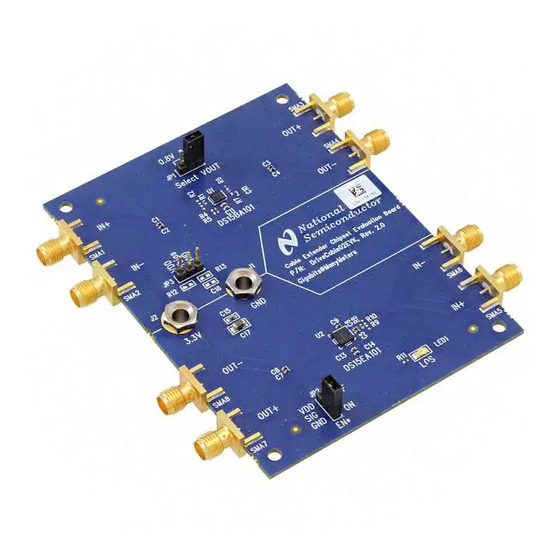
Figure 1 shows a drawing of the board. It is a 3 inch x 4 inch 6-layer PCB with a two-device layout that is capable of demonstrating performance and all features of the DS15BA101 and DS15EA101. Figure 1. DriveCable02EVK Board... -
Page 5: Setting Up The Drivecable02Evk Evaluation Kit
DriveCable02EVK User Manual Setting Up the DriveCable02EVK Evaluation Kit This section provides a quick reference for setting up some typical test configurations using the DriveCable02EVK that will enable you to evaluate the solution with 100-ohm differential cables (twin- axial and twisted pair cables) as well as 50-ohm coaxial cables. Page 5 of 12... -
Page 6: Evaluation With The 100-Ohm Differential Balanced Cables
DriveCable02EVK User Manual Evaluation with 100-ohm Differential Balanced Cables The DriveCable02EVK can be used to evaluate the chipset with 100-ohm differential cables (twin-axial and twisted pair cables). Examples are CAT5e/6/7 cable assemblies such as Belden 1500A, Belden 1700A, Siemon CAT7 Tera, Belden 89207 and Amphenol SKEWCLEAR series of cables. Figure 2 is a simplified block diagram of the configuration. - Page 7 Enable DS15EA101 (U2) outputs by setting its EN* pin to low. This is accomplished by placing a jumper across the GND and SIG pins of the connector JP2. 2. Connect the DS15BA101 inputs to a signal source (e.g. Pattern Generator or Serializer output). a) Note the AC-coupling capacitors on the inputs (SMA1 and SMA2) b) Adjust the signal parameters (VOH, VOL, VCM) so that they comply with the DS15BA101 input requirements.
- Page 8 0.25 UI jitter criteria. 2.50 2.25 2.00 1.75 1.50 1.25 1.00 0.75 0.50 0.25 0.00 Cable Length [m] Figure 3. DS15BA101 and DS15EA101 Performance with CAT5e Cable Page 8 of 12...
- Page 9 (A, B, C and D). The data in red was taken with the 0.5 UI jitter criteria while the data in blue was taken with the 0.25 UI jitter criteria. 3.00 2.75 2.50 2.25 2.00 1.75 1.50 1.25 1.00 0.75 0.50 0.25 0.00 Cable Length [m] Figure 4. DS15BA101 and DS15EA101 Performance with CAT7 Cable Page 9 of 12...
-
Page 10: Evaluation With The 50-Ohm Coaxial Cables
DriveCable02EVK User Manual Evaluating 50-ohm Coaxial Cables The DriveCable02EVK can be used to evaluate 50-ohm coaxial cables. Examples of 50-ohm coaxial cables are Belden 9914 and Andrew FSJ-50B. Figure 5 is a simplified block diagram of the configuration. Advantest D3186 Pattern Generator Cable Extender Chipset Evaluation Board P/N: DriveCable02EVK, Rev. - Page 11 There is a provision to add an optional resistor divider network (R12 and R13) on the DS15BA101 inputs in case one desires bias the signal externally (there is an internal biasing network on the DS15BA101 inputs). In addition, the JP3 connector provides signal biasing provision for a voltage source.
- Page 12 0.25 UI jitter criteria. 3.00 2.75 2.50 2.25 2.00 1.75 1.50 1.25 1.00 0.75 0.50 0.25 0.00 Cable Length [m] Figure 6. DS15BA101 and DS15EA101 Performance with Belden 9914 Cable Page 12 of 12...
- Page 17 (mm) nom: 0.0604 (1.53) Customer Notes: National Semiconductor Total thickness .060" +/- .006" Note pitch is equal to center to center spacing, not edge to edge. Pitch = edge to edge spacing plus one trace width. -------------------------------------------------------------------------------------------------- Impedance Notes 11/26/2007 10:41 AM -------------------------------------------------------------------------------------------------- Layer 1 (ref 2);...
- Page 29 IMPORTANT NOTICE Texas Instruments Incorporated and its subsidiaries (TI) reserve the right to make corrections, modifications, enhancements, improvements, and other changes to its products and services at any time and to discontinue any product or service without notice. Customers should obtain the latest relevant information before placing orders and should verify that such information is current and complete.
- Page 30 Mouser Electronics Authorized Distributor Click to View Pricing, Inventory, Delivery & Lifecycle Information: Texas Instruments DRIVECABLE02EVK/NOPB...
Need help?
Do you have a question about the DS15BA101 and is the answer not in the manual?
Questions and answers