Advertisement
Quick Links
Advertisement

Subscribe to Our Youtube Channel
Related Manuals for National Semiconductor DS10CP152


Summary of Contents for National Semiconductor DS10CP152
- Page 1 1.5 Gbps 2x2 LVDS Crosspoint Switch DS10CP152 Evaluation Kit USER MANUAL Part Number: DS10CP152EVK NOPB For the latest documents concerning these products and evaluation kit, visit lvds.national.com. Schematics and gerber files are also available at lvds.national.com. November 2007 Rev. 0.1...
-
Page 2: Table Of Contents
DS10CP152EVK User Manual Table of Contents Table of Contents ........................2 Overview........................... 3 Description..........................4 Evaluation..........................5 Switch Configuration Truth Tables ................... 6 Typical Performance ........................ 7 Page 2 of 7... -
Page 3: Overview
The DS10CP152EVK is an evaluation kit designed for demonstrating performance of the DS10CP152, a 1.5 Gbps 2x2 LVDS Crosspoint Switch. The evaluation kit is comprised of the DS10CP152 with its associated input and output SMA connectors and jumpers to manually configure the switch. -
Page 4: Description
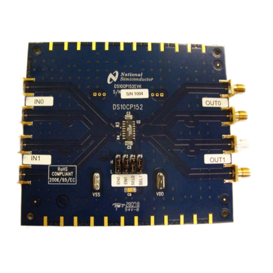
DS10CP152EVK User Manual Description Figure 2 shows the top layer drawing of the PCB with the silkscreen annotations. The 4.5 by 4.0 inch, four-layer PCB is designed to evaluate the functions of the DS10CP152. 0.75" NATIONAL LOGO 0.75" P/N: DS10CP152EVK... -
Page 5: Evaluation
5. Connect an oscilloscope to the selected OUTn outputs and view the output signals with an oscilloscope with the analog bandwidth of at least 3 GHz. Figure 3. DS10CP152 Test Setup Example Page 5 of 7... -
Page 6: Switch Configuration Truth Tables
DS10CP152EVK User Manual Switch Configuration Truth Tables SEL1 SEL0 OUT1 OUT0 Table 1. Switch Configuration Truth Table OUT1 OUT0 Disabled Disabled Disabled Enabled Enabled Disabled Enabled Enabled Table 2. Output Enable Truth Table Page 6 of 7... -
Page 7: Typical Performance
DS10CP152EVK User Manual Typical Performance This section of the User Manual shows a typical eye diagram you can expect to see when evaluating the DS10CP152EVK. Figure 4. DS10CP152 1.5 Gbps NRZ PRBS-7 Output Eye Diagram Page 7 of 7... - Page 13 IMPORTANT NOTICE Texas Instruments Incorporated and its subsidiaries (TI) reserve the right to make corrections, modifications, enhancements, improvements, and other changes to its products and services at any time and to discontinue any product or service without notice. Customers should obtain the latest relevant information before placing orders and should verify that such information is current and complete.
Need help?
Do you have a question about the DS10CP152 and is the answer not in the manual?
Questions and answers