Jøtul GI 635 DV IPI Installation And Operation Instructions Manual
Hide thumbs
Also See for GI 635 DV IPI:
- Installation manual (2 pages) ,
- Manual (4 pages) ,
- Instructions (4 pages)
Table of Contents
Advertisement
40"
1016
mm
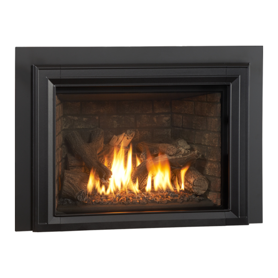
Jøtul GI 635 DV IPI
Direct Vent Fireplace Insert
Installation and
Operation Instructions
INSTALLER: Leave this manual with the appliance.
CONSUMER: Retain this manual for future reference.
139712_R00 GI 635 IPI Sept. 2015
WARNING:
!
FIRE OR EXPLOSION HAZARD. Failure to follow
safety warnings exactly could result in serious
injury, death, or property damage.
– Do not store or use gasoline or other
flammable vapors and liquids in the
vicinity of this or any other appliance.
– WHAT TO DO IF YOU SMELL GAS
• Do not try to light any appliance.
• Do not touch any electrical switch; do
not use any phone in your building.
• Immediately call your gas supplier
from a neighbor's phone. Follow the gas
supplier's instructions.
• If you cannot reach your gas supplier,
call the fire department.
– Installation and service must be
performed by a qualified installer, service
agency or the gas supplier.
– In the Commonwealth of Massachusetts,
a carbon monoxide (CO) detector shall
be installed in the same room as the
appliance.
This appliance may be installed in an aftermarket,
permanently located, manufactured home or
mobile home, where not prohibited by local codes.
This appliance is only for use with the types of gas
indicated on the rating plate. A conversion kit is
supplied with the appliance.
DANGER
!
A barrier designed to reduce the burn hazard
from the glass viewing area is provided with this
appliance and shall be installed for the protection
of children and other at-risk individuals.
HOT GLASS WILL
CAUSE BURNS
.
DO NOT TOUCH GLASS
UNTIL COOLED.
NEVER ALLOW CHILDREN
TO TOUCH GLASS.
1
Advertisement
Table of Contents

Related Manuals for Jøtul GI 635 DV IPI


Summary of Contents for Jøtul GI 635 DV IPI
- Page 1 – Installation and service must be performed by a qualified installer, service agency or the gas supplier. Jøtul GI 635 DV IPI – In the Commonwealth of Massachusetts, a carbon monoxide (CO) detector shall Direct Vent Fireplace Insert be installed in the same room as the appliance.
-
Page 2: Installation & Service Tools
We recommend that � our gas products be installed and serviced by professionals who are certified in the U.S. by the National Fireplace Institute® (NFI) as NFI Gas Specialists. 66.44% 67.85% Natural Gas Propane Jøtul GI 635 DV IPI... -
Page 3: Table Of Contents
139712_R00 GI 635 IPI Sept. 2015 Table of Contents Unpacking the Gas Insert 1. Thoroughly inspect the appliance for shipping damage and Installation & Service Tools ...... 2 immediately contact the dealer if any is found. 2. A Miscellaneous Hardware Kit is packed within the firebox Unpacking the Fireplace ...... -
Page 4: Specifications
Services NA Inc. of Middleton, Wisconsin. Cast Iron Overlay, Matte Black ..........#157725 In addition, the Jøtul GI 635 DV IPI gas fireplace Cast Iron Overlay, Brown Majolica Enamel ......#157726 insert has been tested and listed as a direct vent gas Fuel Conversion Kit - NG to LP (included) ......#157821... -
Page 5: General Information
More frequent cleaning may be required due to excessive lint from carpeting, bedding MODEL NAME: Jøtul GI 635 DV IPI Gas Fireplace Insert material, pet hair, dander, etc. It is imperative that control compartments, burners and circulating air SERIAL NUMBER:_______________________________ passageways of the appliance be kept clean. -
Page 6: Safety Information
139712_R00_GI 635 IPI Sept. 2015 Safety Information Due to the high operating temperatures this appliance should be located out of traffic and away from Electrical Hazards furniture, draperies, etc. Maintain proper clearance to combustible mantels and fireplace trim. Be aware of electrical wiring locations Children and adults should be alerted to the hazards of high surface temperatures and should stay away to when cutting holes in walls and... -
Page 7: Installation
139712_R00 GI 635 IPI Sept. 2015 Leg Leveling Note: 23 ⁄ ” This appliance is equipped with four leveling bolts that can be adjusted by tipping the firebox and unscrewing them from the base. 14 ⁄ ” Also note that use of the 10 ⁄... -
Page 8: Fireplace Requirements
Hearth Requirements Hearth protection in front of the GI 635 DV IPI must be composed of masonry material extending at least 4 1/8” (10.5 cm) to each side of the fireplace opening Minimum Fireplace Dimensions and 12”... -
Page 9: Clearances
139712_R00 GI 635 IPI Sept. 2015 NOTE - Raised Hearth: Forward hearth protection may be reduced by two inches (5.08 cm) for every inch of fireplace floor elevation. Fig. 5. Hearth Extension Forward / Inches Figure 5. Hearth reduction slope. Mantel and Ceiling Clearances Measure clearances from the finished floor of the fireplace 12”... -
Page 10: Vent Guidelines
139712_R00_GI 635 IPI Sept. 2015 Vent Guidelines Vent Installation Procedure • All vent components must be installed in accordance This appliance must be vented through the chimney with the terms of their listing and manufacturer’s by a pair of 3 inch flexible aluminum liners listed for instructions. -
Page 11: Masonry Fireplaces
139712_R00 GI 635 IPI Sept. 2015 Venting through a Masonry Fireplace IMPORTANT NOTICE: INSTALLATION OF A HIGH-WIND TERMINATION CAP IS RECOMMENDED FOR ALL IPI APPLIANCES TO HELP 1. Measure height of the chimney to fireplace opening. INCREASE PERFORMANCE. Determine if both the intake and exhaust will be We Recommend: extended to the top of the chimney. -
Page 12: Prefabricated Fireplaces
139712_R00_GI 635 IPI Sept. 2015 IMPORTANT NOTICE: Prefabricated Fireplace Installation INSTALLATION OF A HIGH-WIND TERMINATION CAP IS RECOMMENDED FOR ALL IPI APPLIANCES TO HELP IMPORTANT: INCREASE PERFORMANCE. BEFORE STARTING THIS INSTALLATION, MAKE SURE THAT We Recommend: A GAS LINE CAN BE INSTALLED OR IS INSTALLED TO THE •... -
Page 13: Vent Connection
139712_R00 GI 635 IPI Sept. 2015 Vent Connection Prefabricated Fireplace Vent Procedure 1. Measure height of the chimney to fireplace Wear Safety Gloves! opening. Determine if both the intake and exhaust will be extended to the top of the 1. Remove the Lock Screw from the Vent Adaptor Panel chimney. -
Page 14: Fireplace Assembly
Gas Pressure Test valve regardless of the input setting. See fig. 10-11. The GI 635 DV IPI is shipped a 36” length of flexible Correct gas pressure is essential for efficient and gas 3/8” gas line. Jøtul recommends the use of the safe operation of the gas insert. - Page 15 139712_R00 GI 635 IPI Sept. 2015 REQUIRED INLET GAS PRESSURES (inches water column) Figure 12. NATURAL GAS 4.0 WC 7.0 WC Pressure test points. PROPANE 12.0 WC 14.0 WC Inlet Manifold REQUIRED MANIFOLD PRESSURES (inches water column) NATURAL GAS 1.1 WC 3.8 WC PROPANE 2.9 WC...
-
Page 16: Fuel Conversion
This action retracts the shutters and allows the burner to The Jøtul GI 635 DV IPI is shipped from the factory be disengaged from the firebox. See figs. 16 and 58. - Page 17 139712_R00 GI 635 IPI Sept. 2015 Figure 14. Fuel Conversion Components. Pilot Assembly Rear Burner Injector Rear Burner Air Shutter Cable Front Burner Injector Front Burner Air Shutter Cable Air Shutter Adjustor Trays Pilot Head Flame Ignitor Sensor Pilot Orifice Lever Remove Heat Shield Figure 15.
-
Page 18: High Altitude Adjustment
139712_R00_GI 635 IPI Sept. 2015 High Altitude Adjustment JØTUL ORIFICE When installing this appliance at altitude above 2000 ELEVATION PART NO. SIZE feet, it is necessary to compensate for the thinner air (less volume of air per cubic foot). Higher altitudes affect 2.20 mm - L 2001’- 4500’... - Page 19 139712_R00 GI 635 IPI Sept. 2015 This page is intentionally blank.
-
Page 20: Brick Panel Kits
139712_R00_GI 635 IPI Sept. 2015 Install Optional Brick Panels Figure 18. Remove burner assembly. Tools Required 157686 Traditional Red • Rear Panel - 225793 Flat Head Screwdriver • Left Side Panel - 225794 • Right Side Panel - 225795 157798 Brownstone •... - Page 21 139712_R00 GI 635 IPI Sept. 2015 Figure 22. Install side panels. Figure 25. Engage burner bracket with floor stud. SUPPORT BRACKET STUD Figure 23. Set retaining tab. Figure 26. Replace burner assembly. Figure 24. Set air shutter adjuster trays (A) fully open. Figure 27.
-
Page 22: Reflective Glass Panel Kit
139712_R00_GI 635 IPI Sept. 2015 Install Optional Reflective Glass Panels 157803 Kit Contents Tools Required • Left Side Panel - 225768 Spade Screwdriver • Center Panel - 225769 Safety Gloves • Right Side Panel - 225770 ! CAUTION ! THE PANELS ARE VERY FRAGILE. WHILE MANEUVERING THE PANELS INTO POSITION, BE CAREFUL TO AVOID STRIKING CORNERS AND EDGES ON THE FIREBOX PARTS. - Page 23 139712_R00 GI 635 IPI Sept. 2015 Figure 31. Bend retainer tabs against the glass panel. Figure 32. Install the Side Panels. Figure 33. Replace retainer brackets opposite from original orientation.
-
Page 24: Log Set Installation
139712_R00_GI 635 IPI Sept. 2015 Figure 36. #2 Log: The flat pads on the underside of the log Install the Log Set rest on the flat landings in the burner base. NOTE: Install the optional Brick Panels before installing the Log Set. Install the log set in the order presented here. - Page 25 139712_R00 GI 635 IPI Sept. 2015 Figure 42. #4 Log: The ceramic stub in the base of the log Figure 39. #3 Log: Two rounded notches in the bottom of sets into the back of the slot in right side of the burner the log align with matching nubs in the right side of base.
- Page 26 139712_R00_GI 635 IPI Sept. 2015 Figure 45. #5 Log: The notch [A] at the upper end mates with the stub [A] protruding from Log #4. Figure 48. The flat pad [B]at the lower end rests on the matching flat [B] in the burner base. FOR #6 Figure 49.
- Page 27 139712_R00 GI 635 IPI Sept. 2015 Figure 50. #6 Log: Engage the underside hole with the Figure 53. Use tweezers to pinch small tufts of Rock right peg on Log #1. Rest the forward end of the log in Wool very sparsely around the burner base. the shallow groove on top of Log #5.
-
Page 28: Backer Plate Installation
139712_R00_GI 635 IPI Sept. 2015 NOTE: COMPLETE FUEL CONVERSION, HIGH ALTITUDE ADJUSTMENT, AND BRICK OR GLASS PANEL INSTALLATION BEFORE ASSEMBLING BACKER PLATES. FOR #5 Figure 55. Standard Backer Plate Backer Plate installation. Installation The standard Backer plates each incorporate hanger brackets to which the Front Cast Iron Overlay Assembly will be attached. -
Page 29: Hidden Hanger Bracket
139712_R00 GI 635 IPI Sept. 2015 Hidden Hanger Bracket Installation The Hidden Overlay Hanger Brackets are used for installations that do not require the standard Backer Plate. They provide a means of attachment for the Front Cast Iron Overlay assembly. Left Bracket 225765 Right Bracket 225766... -
Page 30: Operation
139712_R00_GI 635 IPI Sept. 2015 Operation Initial System Check and WARNING: General Operation READ AND UNDERSTAND ALL OPERATING INSTRUCTIONS BEFORE ATTEMPTING TO OPERATE THIS APPLIANCE. DO NOT ALLOW ANYONE TO This appliance is designed to be operated with use of OPERATE THIS APPLIANCE WHO HAS NOT READ AND the Remote Control System. - Page 31 139712_R00 GI 635 IPI Sept. 2015 8. IMPORTANT: It will be necessary to clean the glass OPEN after the first few fires. A white powdery residue will be evident which results from the burner media curing. Use a non-abrasive household glass cleaner or warm water.
-
Page 32: Fireplace Operation
139712_R00_GI 635 IPI Sept. 2015 Fireplace Operation Burner Switch • OFF : The Burner will not operate. • ON : Power is available for all Burner functions. Pilot Modes • Continuous Pilot Ignition ( CPI ) This permits the pilot to continue burning even when there is no call for heat. -
Page 33: Remote Control Functions
139712_R00 GI 635 IPI Sept. 2015 Proflame 2 Remote Control Pilot Assembly The pilot assembly consists of a pilot hood, electrode, and a flame sensor. The electrode sends a spark to the pilot Features Overview hood which ignites the gas. The sensor is then engulfed by the pilot flame, flame rectification occurs and the pilot remains lit. -
Page 34: Remote Control Functions
139712_R00_GI 635 IPI Sept. 2015 Remote Control Functions IFC / Transmitter Mode Synchronization 1. Set the Burner Switch to OFF, (located in the right side Pilot Mode Control compartment). The IPI/CPI functionality will be fully controlled by 2. Install three AAA batteries into the Transmitter. the remote transmitter. - Page 35 139712_R00 GI 635 IPI Sept. 2015 Remote Transmitter Controls Temperature Indication Display With the transmitter in the OFF position, press the Thermostat Key and the Mode Key at the same time. The display screen will show the current room temperature cycling between Fahrenheit and Celsius indicators each time the keys are pressed Figure 65.
- Page 36 139712_R00_GI 635 IPI Sept. 2015 Room Thermostat (Transmitter Operation) The Remote Control can operate as a room thermostat. Room Temperature The thermostat can be set to a desired temperature to control the comfort level in a room. To activate this function, press the Thermostat Key. The ...
-
Page 37: Maintenance
139712_R00 GI 635 IPI Sept. 2015 Maintenance Accent Lamp Replacement CAUTION: THE IGNITION SYSTEM OF THIS APPLIANCE CARRIES 1. Remove the cast iron overlay assembly, backer plate, LIVE VOLTAGE. ALWAYS TURN OFF THE GAS SUPPLY and glass frame., TO THE INSERT AND DISCONNECT THE POWER 2. -
Page 38: Glass Care And Replacement
139712_R00_GI 635 IPI Sept. 2015 Glass Care Moisture condensation is a normal occurrence with gas appliances and particulate accumulation may appear on the inside surface to the glass. Use a dampened, soft cloth to clean the glass and polish with a dry, soft towel. Specially-formulated ceramic glass cleaner may also be used. -
Page 39: Illustrated Part Breakdowns
139712_R00 GI 635 IPI Sept. 2015 Jøtul GI 635 DV IPI Replacement Parts ONLY USE REPLACEMENT PARTS PROVIDED BY AN AUTHORIZED JØTUL DEALER. Figure 86. Controls components, right side compartment. No. Part Number Description 225797 Controls, Skid Plate 225694 Latch Handle... - Page 40 139712_R00_GI 635 IPI Sept. 2015 Figure 87. SHEET Valve Train components, left side compartment. 1 OF 1 SCALE 0.375 NG DATE: 8/4/15 No. Part Number Description No. Part Number Description 225676 Flex Tube, Main Gas - 5/16” OD x 24” 225527 Valve Heat Shield 129464...
- Page 41 139712_R00 GI 635 IPI Sept. 2015 2 X 1/4 Figure 88. Internal firebox components. No. Part Number Description 225490 Baffle 225693 Side Panel Retainer 225511 Rear Log Support 225681 Pilot Assembly / Integrated Dual Fuel 157831 Right Cable Assembly 157744 Burner Assembly 225648 Pilot Bracket...
- Page 42 104676 SURROUND LEG RIGHT 104677 PLINTH 225783 HANGING BRACKET 139712_R00_GI 635 IPI Sept. 2015 225785 ADJ. SCREEN RETAINER 225786 TOP CORNER BRACKET 225784 SCREEN RETAINER TOP 117978 M6 X 10 BUTTON HEAD 225787 BOTTOM CORNER BRACKET 225788 BOTTOM SHADE 225782 BULK HEAD, SCREEN ADJ.
- Page 43 139712_R00 GI 635 IPI Sept. 2015 Figure 90. Blower Assembly Figure 91. Glass components. No. Part Number Description No. Part Number Description 117917 Screw, HWH SMA 8 x 1/2 SL Blk Oxide 129124 Gasket, Fiber Glass w/ Graphite, .25” x 1.25 “, 8.5 ft. 225494 Blower Bracket, Left and Right 157834...
-
Page 44: Approved Vent Manufacturers
139712_R00_GI 635 IPI Sept. 2015 Appendix Pro ame 2 Stepper Regulator Figure 93. GI 635 DV IPI Proflame 2 Wiring Diagram. SIT Pro ame Valve Split Flow Valve Battery Pack Four, 1.5v AA Main Burner Switch Optional Accent Dual Blowers... -
Page 45: Warranty Statement
139712_R00 GI 635 IPI Sept. 2015 Jøtul GI 635 DV IPI Fireplace 2) Damage due to incorrect installations not in conformance with the Insert Limited Lifetime Warranty installation instructions contained in this owner’s manual or local and/or national fire and building regulations. - Page 46 139712_R00_GI 635 IPI Sept. 2015...
-
Page 47: Lighting Instructions
139712_R00 GI 635 IPI Sept. 2015 LIGHTING INSTRUCTIONS FOR YOUR SAFETY, READ BEFORE LIGHTING. WARNING: IF YOU DO NOT FOLLOW THESE INSTRUCTIONS EXACTLY, A FIRE OR EXPLOSION MAY RESULT CAUSING PROPERTY DAMAGE, PERSONAL INJURY, OR LOSS OF LIFE. A. This appliance is equipped with an ignition device which automatically lights the pilot. Do not try to light the pilot by hand. - Page 48 139712_R00_GI 635 IPI Sept. 2015 This appliance must be installed in conformance with local and national building regulations. Before beginning the installation, it is important that the these instructions be carefully read and understood. Jøtul maintains a policy of continuous product development. Consequently, products may differ in specification, color or type of accessories from those illustrated or described in various publications.
Need help?
Do you have a question about the GI 635 DV IPI and is the answer not in the manual?
Questions and answers