Oki OKIPAGE 10e Maintenance Manual
Led page printer
Hide thumbs
Also See for OKIPAGE 10e:
- Service manual (266 pages) ,
- User manual (46 pages) ,
- Setup manual (20 pages)

Related Manuals for Oki OKIPAGE 10e

Summary of Contents for Oki OKIPAGE 10e
-
Page 1: Maintenance Manual
OKIPAGE 10e LED Page Printer Maintenance Manual ODA / OEL / INT 1999.11. 30 Rev.2 1 / 173 41154001TH Rev.2... - Page 2 Revision History Table Corrected items Person in Rev.No. Date Page Description of change change 1999.10.22 ISSUE E5 Miyashita 1999.11.30 Table 8-1 Add No.50. E5 Otake 41154001TH Rev.2...
- Page 3 PREFACE This Maintenance Manual describes the field maintenance methods for OKIPAGE 10e LED Page Printers. This manual is written for use by the maintenance personnel. Please note that you should refer to the Printer Handbook and Printer Setup for the handling and operating methods of the equipment.
-
Page 4: Table Of Contents
Contents CONFIGURATION ..................... 77 1.1 System Configuration ..................7 1.2 Printer Configuration ..................9 1.3 Optional Configuration .................. 10 1.4 Specification ....................12 1.5 Safety Standards ..................14 1.5.1Certification Label ...................... 14 1.5.2Warning Label ......................14 1.5.3Warning/Caution Marking ..................15 OPERATION DESCRIPTION ................ - Page 5 PARTS LIST ......................116 Appendix A RS-232C SERIAL INTERFACE (option) ..........123 Appendix B CENTRONICS PARALLEL INTERFACE ..........126 APPENDIX C MAINTENANCE UTILITY GUI MANUAL (OKIPAGE 10e) ....130 APPENDIX D MULTI-PURPOSE FEEDER ............134 1. OUTLINE ...................... 134 1.1 Functions ....................134 1.2 External View and Component Names ..........
- Page 6 3.3 Parts Replacement Methods ..............139 3.3.1 Link ......................... 140 3.3.2 Separator ........................ 141 3.3.3 OLEV-11-PCB ......................142 3.3.4 Pulse Motor ......................143 3.3.5 Planet Gear ......................144 3.3.6 Roller-A and B ......................145 4. TROUBLESHOOTING ................. 146 4.1 Precautions Prior to the Troubleshooting ..........146 4.2 Preparations for the Troubleshooting ...........
-
Page 7: System Configuration
CONFIGURATION System Configuration OKIPAGE 10e consists of control and engine blocks in the standard configuration, as shown in Figure 1-1. In addition, the options marked with asterisk(*) are available. 41154001TH Rev.2... -
Page 8: Figure
Operator Panel Engine Unit Paper Cassette Face Up Stacker *High Capacity Second Paper Paper Feeding Mechanism Feeder (First Tray Unit) Face *Multi Purpose Down Feeder Stacker Electrophotographic Processing Unit Power Supply and Sensor Board Centronics Main Control Board * : Optional Memory* Expansion Board 1 DRAM SIMM Socket... -
Page 9: Printer Configuration
Printer Configuration The printer unit consists of the following hardware components: • Electrophotographic Processor • Paper Feeder • Controller • Operator Panel • Power Supply Unit The printer unit configuration is shown in Figure 1-2. Upper cover Operator panel assy Toner-cartridge(Type 5) (consumable) Stacker assy... -
Page 10: Optional Configuration
Optional Configuration The options shown below are available for use with OKIPAGE 10e. These are available separately from the printer unit. (1) High Capacity Second Paper Feeder (2) Multi Purpose Feeder (3) 1MB Memory Expausion Board 10 / 41154001TH Rev.2... - Page 11 (4) RS-232C Serial Interface Board (5) DRAM SIMM Memory DRAM SIMM memory is available with memory of 2, 4, 8, 16 or 32MB. The access time of SIMM memories are 60ns, 70ns, 80ns, and 100ns. (6) Flash SIMM Flash SIMM is available with memory of 4MB and 8MB. 11 / 41154001TH Rev.2...
-
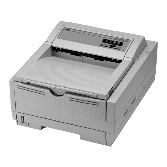
Page 12: Specification
Specification (1) Type Desktop (2) External dimensions Height 7.9” (200 mm) Width 13.0” (330 mm) Depth 15.6” (395 mm) (3) Weight Approx. 10 kg (4) Developing method Dry electrophotography Exposing method LED stationary head (5) Paper used <Type> • Standard paper –... - Page 13 (10) Power input 120 VAC + 5.5%, -15% 230 VAC ± 10% (11) Power consumption Peak: Approx. 460W Typical operation: Approx. 215W Idle: Approx. 61W Power save mode: Approx. 18W (12) Temperature and humidity In operation Power off mode During Storage Unit Temperature 50-90...
-
Page 14: Safety Standards
Safety Standards 1.5.1 Certification Label The safety certification label is affixed to the printer in the position described below. INT AC : 230V model ODA AC : 120V model ODA AC : 230V model 1.5.2 Warning Label The warning labels are affixed to the sections which may cause bodily injury. Follow the instructions on warning labels during maintenance. -
Page 15: 3Warning/Caution Marking
1.5.3 Warning/Caution Marking The following warning and caution markings are made on the power supply/sensor board. WARNING AVERTISSEMENT ADVERTENCIA CAUTION HEATSINK AND TRANSFORMER ATTENTION ATENCÃO PRESENT RISK OF ELECTRIC SHOCK CUIDADO CUIDÃDO TEST BEFORE TOUCHING * No fuse is mounted here for 200V series ENGLISH Heatsink and transformer core present risk of electric shock. -
Page 16: Operation Description
OPERATION DESCRIPTION OKIPAGE 10e consists of a main control board, a power supply/sensor board, an operator panel, an electrophotographic process mechanism, and revision for illumination of LED head. The main control board receives data via the host I/F, it then decodes, edits and stores the data in memory. - Page 17 Paper sensor Toner supply roller Outlet sensor Cleaning roller Thermistor Paper out sensor Fusing temperature control circuit Heater drive Toner low sensor Heater circuit transformer Filter circuit AC IN Figure 2-1 OKIPAGE 10e Block Diagram 17 / 41154001TH Rev.2...
-
Page 18: Main Control Board
Main Control Board The main control board consists of a single chip CPU, two program/font ROMs, two DRAMs, an EEPROM, a host interface circuit, and a mechanism driving circuit. (1) Single chip CPU The single chip CPU is a custom CPU (32-bit internal bus, 32-bit external bus, 28.24-MHz clock, with input frequency from a 7.06-MHz clock) which incorporates the RISC CPU and its peripheral devices, and has the following functions: Built-in device... -
Page 19: Power Supply/Sensor Board
Power Supply/Sensor Board The power supply/sensor board consists of an AC filter circuit, a low voltage power supply circuit, a high voltage power supply circuit, heater drive circuit, and photosensors. (1) Low Voltage Power Supply Circuit This circuit generates the following voltages. Output voltage +5 V Logic circuit supply voltage and LED head supply voltage... - Page 20 The sensor layout diagram is shown in Figure 2-2. Exit roller Outlet sensor Heat roller Transfer roller Paper sensor Toner Inlet sensor sensor 2 Registration roller Paper end sensor Hopping roller Inlet sensor 1 Figure 2-2 Sensor Function Sensing state Inlet sensor 1 Detects the leading part of the paper and gives the monitor timing ON: Paper exists.
-
Page 21: Electrophotographic Process
Electrophotographic Process 2.3.1 Electrophotographic Process Mechanism This mechanism actuates the printing of image data supplied by the main control board on the paper by electrophotographic process. The layout of the electrophotographic process mechanism is shown in Figure 2-3. 21 / 41154001TH Rev.2... - Page 22 Figure 2-3 22 / 41154001TH Rev.2...
- Page 23 (1) Image Drum Unit The image drum unit consists of a sensitive drum, a charger, and a developer. The unit forms a toner image on the sensitive drum, using a electrostatic latent image formed by the LED head. (2) Registration Motor The registration motor is a pulse motor of 48 steps/rotation with two-phase excitement by the signal from the main control board.
-
Page 24: Electrophotographic Process
2.3.2 Electrophotographic Process The electrophotographic processing is outlined below. The electrophotographic printing process is shown in Figure 2-4. 1 Charging The surface of the image drum is charged uniformly with a negative charge by applying the negative voltage to the charge roller. 2 Exposure Light emitted from the LED head irradiates the negatively charged surface of the image drum. - Page 25 Figure 2-4 25 / 41154001TH Rev.2...
- Page 26 Figure 2-5 26 / 41154001TH Rev.2...
-
Page 27: Process Operation Descriptions
2.3.3 Process Operation Descriptions (1) Hopping and Feeding Hopping and feeding motions are actuated by a single registration motor in the mechanism as shown below: Registration motor Idle gear Registration roller Hopping roller Motor gear Registration gear Hopping gear The registration motor turning in direction "a" drives the hopping roller. The registration motor turning in direction "b"... - Page 28 Hopping 1 For hopping, the registration motor turns in direction "a" (clockwise direction) and drives the hopping roller to advance the paper until the inlet sensor turns on (in this case, the registration gear also turns, but the registration roller is prevented from turning by the one-way bearing).
- Page 29 (2) Charging Charging is actuated by the application of the DC voltage to the charge roller that is in contact with the image drum surface. Power Charge roller supply Image drum The charge roller is composed of two layers, a conductive layer and a surface protective layer, both having elasticity to secure good contact with the image drum.
- Page 30 (3) Exposure Light emitted by the LED head irradiates the image drum surface with a negative charge. The surface potential of the irradiated portion of the image drum drops, forming an electrostatic latent image associated with the image signal. LED head LED head Charge roller Power...
- Page 31 The image roller surface is charged to about –750 V by the contact charge of the charge roller. When the light from the LED head irradiates the image drum surface, the light energy generates positive and negative carriers in the CGL. The positive carriers are moved to the CTL by an electrical field acting on the image drum.
- Page 32 (4) Developing Toner is attracted to the electrostatic latent image on the image drum surface, converting it into a visible toner image. Developing takes place through the contact between the image drum and the developing roller. 1 As the toner supply roller rotates while rubbing on the developing roller, a friction charge is generated between the developing roller and the toner, allowing the toner to be attracted to the developing roller (the developing roller surface is charged positive and the toner, negative).
- Page 33 Note: The bias voltage required during the developing process is supplied to the toner supply roller and the developing roller, as shown below. –500 VDC is supplied to the toner supply roller, –265 VDC to the developing roller. Connected and bias supplied when the cover is closed.
- Page 34 (5) Transfer The transfer roller is composed of conductive sponge material, and is designed to get the image drum surface and the paper in a close contact. Paper is placed over the image drum surface, and the positive charge, opposite in polarity to that of the toner, is applied to the paper from the reverse side.
- Page 35 (6) Fusing When the transfer is completed, the toner image is fused to the paper by heat and pressure as the paper with unfused toner image passes between the heater roller and the back-up roller. The heater roller with Teflon coating incorporates a 400W heater (Halogen lamp), which generates heat.
- Page 36 (7) Cleaning When the transfer is completed, the residual toner left on the image drum is attracted to the cleaning roller temporarily by static electricity, and the image drum surface is cleaned. Image drum Cleaning roller Power supply Transfer roller (8) Cleaning of rollers The charge, transfer and cleaning rollers are cleaned for the following cases: •...
-
Page 37: Paper Jam Detection
Paper Jam Detection The paper jam detection function monitors the paper condition when the power is turned on and during printing. When any of the following conditions arises, this function interrupts the printing process. If any of the following errors is encountered, printing can be recovered by removing the jammed paper (by opening the upper cover, removing the jammed paper and closing the upper cover). - Page 38 Paper Feed Check List Error Type of error Monitor Standard value Plus Minus Paper feed error Hopping start In sensor on 72.0 36.0 – Paper feed jam In sensor on Write sensor on 20.0 22.0 – Paper feed jam Write sensor on Out sensor on 140.5 25.0...
-
Page 39: Cover Open
Cover Open When the stacker cover is opened, the cover open microswitch on the power supply/sensor board is turned off to cut +5V supply to the high voltage power supply circuit. This results in the interruption of all high-voltage outputs. At the same time, the CVOPN signal is sent to the main control board to notify that the microswitch is off, and the main control board carries out the cover open process. -
Page 40: Toner Low Detection
Toner Low Detection • Device The Toner Low Detection device consists of a stirring gear which rotates at a constant rate, a stirring bar and a magnet on the stirring bar. The stirring bar rotation is driven by the link to the gouged portion in the stirring gear. -
Page 41: Toner Full State
TONER FULL state 160 ms < t1 < 0.8 sec TNRSNS-N 2.63 sec. TONER LOW state t1 > 0.8 sec. TNRSNS-N 2.63 sec. • When the Toner Low state is detected 2 times consecutively, Toner Low is established. • When the Toner Full state is detected 2 times consecutively, Toner Low is cancelled. •... -
Page 42: Parts Replacement
PARTS REPLACEMENT This section explains the procedures for replacement of parts, assemblies, and units in the field. Only the disassembly procedures are explained here. For reassembly, reverse the disassembly procedure. Precautions for Parts Replacement (1) Before starting to replace parts, remove the AC cord and interface cable. Remove the AC cord in the following sequence: Turn off (“o”) the power switch of the printer Disconnect the AC inlet plug of the AC cord from the AC receptacle. - Page 43 [Service Tools] The tools required for field replacement of printed circuit boards, assemblies and units are listed in Table 3-1. Table 3-1 Service Tools Service Tools Q' ty Application Remarks No. 1-100 Philips screwdriver 2~2.5 mm screws No. 2-100 Philips screwdriver 3~5 mm screws No.
-
Page 44: Parts Layout
Parts Layout This section explains the layout of main components of the equipment. [Lower base unit] Pulse motor Stacker cover assy (main/drum) Eject roller assy Back-up roller View A Pulse motor Transfer roller (registration) Diselectrification bar Registration roller Spacer bearing R Fusing unit Spacer bearing L Lower base unit... - Page 45 [Upper cover unit] Upper cover Figure 3-2 45 / 41154001TH Rev.2...
- Page 46 [Base unit] Operator panel assy Power supply/ sensor board Transformer Face up stacker assy DC fan assy Main control board Cassette guide (R) Cassette guide(L) Paper cassette Figure 3-3 46 / 41154001TH Rev.2...
-
Page 47: How To Change Parts
How to Change Parts This section explains how to change parts and assemblies listed in the disassembly diagram below. In the parts replacement procedure, those parts marked with the part number inside with white letters are RSPL parts. Printer unit Upper cover assy Operator panel assy Face up stacker assy... -
Page 48: Upper Cover Assy
3.3.1 Upper Cover Assy (1) With the power switch turned off, unplug the AC power cord from the outlet. (2) Disconnect the interface cable 1. (3) Press the knobs 2 on left and right sides and open the stacker cover assy 3. (4) Take out the image drum unit 4. -
Page 49: Ic Card Cover
3.3.2 IC Card Cover (1) Open the IC card cover 1, press it from both sides at the hinges in the directions of arrows shown below and remove it. 49 / 41154001TH Rev.2... -
Page 50: Led Head
3.3.3 LED Head (1) Press the knobs on left and right sides and open the stacker cover assy 1. (2) Open the hook section on the left side of the stacker cover and remove the LED head 2. Note: • Be sure not to touch directly or push on the SLA part of the LED head. -
Page 51: Operator Panel Assy
3.3.4 Operator Panel Assy (1) Unlock two latches on the upper cover from the rear side, lift the operator panel assy 1 from the back and remove it. (2) Remove the Sumi card (operator panel) 2 from the connector (CN1) 3. Note : You can remove the operator panel assy while the upper cover installed on the unit. -
Page 52: Lower Base Unit
3.3.5 Lower Base Unit (1) Remove the upper cover assy (see 3.3.1). (2) Remove the operator panel assy (see 3.3.4). (3) Remove the face up stacker assy (see 3.3.8). (4) Remove the connecting cables 2 and 3 of the pulse motors from the connectors (DM, RM) of the M5G-PCB 1. -
Page 53: Pulse Motor (Main/Drum)
3.3.6 Pulse Motor (Main/Drum) (1) Remove the upper cover assy (see 3.3.1). (2) Remove the lower base unit (see 3.3.5). (3) Remove two screws 1 and remove the pulse motor (main/drum) 2 from the motor bracket View A View A 53 / 41154001TH Rev.2... -
Page 54: Pulse Motor (Registration)
3.3.7 Pulse Motor (Registration) (1) Remove the upper cover assy (see 3.3.1). (2) Remove the lower base unit (see 3.3.5). (3) Remove two screws 1 and remove the pluse motor (registration) 2 from the motor bracket View A View A 54 / 41154001TH Rev.2... -
Page 55: Face Up Stacker Assy
3.3.8 Face Up Stacker Assy (1) Remove the upper cover assy (see 3.3.1). (2) Remove the operator panel assy (see 3.3.4). (3) Remove the screw 1 and remove the Sumi card (operator panel cable) 2 off the latch section of face up stacker 4. Remove both the shield plate 3 and face up stacker 4 together. (4) Unlock the latches at two locations, and remove the face up stacker 4. -
Page 56: Eject Roller Assy
3.3.9 Eject Roller Assy (1) Remove the upper cover assy (see 3.3.1). (2) Remove the operator panel assy (see 3.3.4). (3) Remove the face up stacker assy (see 3.3.8). (4) Remove the lower base unit (see 3.3.5). (5) Disengage the eject roller assy 1 from the lower base 2 by pressing the latch section of the eject roller assy 1 in the direction of the arrow shown below, and remove the eject roller assy LATCH 56 /... -
Page 57: 3.3.10 Motor Assy
3.3.10 Motor Assy (1) Remove the upper cover assy (see 3.3.1). (2) Remove the operator panel assy (see 3.3.4). (3) Remove the face up stacker assy (see 3.3.8). (4) Remove the lower base unit (see 3.3.5). (5) Stand the lower base unit on its side as shown, and unlock two latches, then remove the motor assy 1. -
Page 58: Hopping Roller Shaft Assy
3.3.11 Hopping Roller Shaft Assy (1) Remove the upper cover (see 3.3.1). (2) Remove the operator panel assy (see 3.3.4). (3) Remove the face up stacker assy (see 3.3.8). (4) Remove the lower base unit (see 3.3.5). (5) Remove the motor assy (see 3.3.10). (6) With the lower base unit 1 standing on its side, remove the one-way clutch gear 2 and the bearing (A) 3. -
Page 59: Stacker Cover Assy
3.3.12 Stacker Cover Assy (1) Remove the upper cover assy (see 3.3.1). (2) Remove the operator panel assy (see 3.3.4). (3) Remove the face up stacker assy (see 3.3.8). (4) Remove the reset lever R 1. (5) Detach the reset spring 2 from the lower base unit 3, turn the reset lever L 4 in the direction of arrow until it stops, and remove it in the direction of arrow (6) Unlock two latches of the lower base unit 3, then remove the stacker cover assy 5. -
Page 60: Registration Roller
3.3.13 Registration Roller (1) Remove the upper cover (see 3.3.1). (2) Remove the operator panel assy (see 3.3.4). (3) Remove the face up stacker assy (see 3.3.8). (4) Remove the lower base unit (see 3.3.5). (5) Remove the motor assy (see 3.3.10). (6) With the lower base unit standing on its side, remove the one-way clutch gear 1. -
Page 61: 3.3.14 Roller Transfer Assy
3.3.14 Roller Transfer Assy (1) With the power switch turned off, unplug the AC cord from the outlet. (2) Open the stacker cover. (3) Release the roller transfer assy 1 by unlocking the latch of the main unit (never apply excessive force when unlocking the latch). -
Page 62: 3.3.15 Fusing Unit
3.3.15 Fusing Unit (1) Remove the upper cover (see 3.3.1). (2) Remove the operator panel assy (see 3.3.4). (3) Remove the face up stacker assy (see 3.3.8). (4) Remove the stacker cover assy (see 3.3.12). (5) Remove four screws 1, lift and remove the fusing unit 2. Caution: Fusing unit may be hot. -
Page 63: 3.3.16 Back-Up Roller
3.3.16 Back-up Roller (1) Remove the fusing unit assy (see 3.3.15). (2) Lift the left side of the back-up roller 1, and pull it out to the left side (at this time, two bushings (back-up) 2 and the bias springs (back-up) 3 will also come off). 63 / 41154001TH Rev.2... -
Page 64: Sensor Plate (Inlet)
3.3.17 Sensor Plate (Inlet) (1) Remove the upper cover (see 3.3.1). (2) Remove the operator panel assy (see 3.3.4). (3) Remove the face up stacker assy (see 3.3.8). (4) Remove the lower base unit (see 3.3.5). (5) Press the clamps of three sensor plates (inlet and paper) 1, and remove them by pressing them upward from the bottom. -
Page 65: Sensor Plate (Outlet)
3.3.18 Sensor Plate (Outlet) (1) Remove the upper cover assy (see 3.3.1). (2) Remove the operator panel assy (see 3.3.4). (3) Remove the eject roller assy (see 3.3.9). (4) Remove the face up stacker assy (see 3.3.8). (5) Remove the lower base unit (see 3.3.5). (6) Remove the fusing unit assy (see 3.3.15). -
Page 66: Manual Feed Guide Assy
3.3.19 Manual Feed Guide Assy (1) Remove the upper cover assy (see 3.3.1). (2) Open the manual feed guide assy 1, and release the engagement on both sides with the main unit by carefully bending the manual feed guide assy 1. Note : When remounting, verify the proper the engagements as shown in the diagram. -
Page 67: Sensor Plate (Paper Supply)
3.3.20 Sensor Plate (Paper Supply) (1) Remove the upper cover assy (see 3.3.1). (2) Remove the operator panel assy (see 3.3.4). (3) Remove the face up stacker assy (see 3.3.8). (4) Remove the lower base unit (see 3.3.5). (5) Press the clamps of the sensor plate (paper supply) 1 to unlock the latch, and remove it from the base plate 2. -
Page 68: M5G-Pcb
3.3.21 M5G-PCB (1) Remove the upper cover assy (see 3.3.1). (2) Remove the operator panel assy (see 3.3.4). (3) Remove the face up stacker assy (see 3.3.8). (4) Remove the lower base unit (see 3.3.5). (5) Remove the connector (2NDTRAY) 6. (6) Remove three screws 1. -
Page 69: 3.3.22 Transformer
3.3.22 Transformer (1) Remove the upper cover assy (see 3.3.1). (2) Remove the operator panel assy (see 3.3.4). (3) Remove the face up stacker assy (see 3.3.8). (4) Remove the connectors (CN1 and CN2). (5) Remove two screws 1, and remove the transformer 2. Note : When reinstalling the transformer, be sure to lay the AC and transformer’s primary side cables under the divider (see view A diagram below). -
Page 70: 3.3.23 Power Supply/Sensor Board And Contact Assy
3.3.23 Power Supply/Sensor Board and Contact Assy (1) Remove the upper cover assy (see 3.3.1). (2) Remove the lower base unit (see 3.3.5). (3) Remove the M5G-PCB (See 3.3.21). (4) Remove the transformer (see 3.3.22). (5) Remove the AC inlet 1 from the base plate 2. (6) Remove the screw 3 and remove the grounding (earth) wire 4. -
Page 71: 3.3.24 Cassette Guide L Assy
3.3.24 Cassette Guide L Assy (1) Remove the paper cassette. (2) Remove the upper cover assy (see 3.3.1). (3) Remove the lower base unit (see 3.3.5). (4) Remove the M5G-PCB (see 3.3.21). (5) Remove the transformer (see 3.3.22). (6) Remove the power supply/sensor board (see 3.3.23). (7) Remove two screws 1, and remove the guide rails 2. -
Page 72: 3.3.25 Cassette Guide R Assy
3.3.25 Cassette Guide R Assy (1) Remove the paper cassette. (2) Remove the upper cover assy (see 3.3.1). (3) Remove the lower base unit (see 3.3.5). (4) Remove the M5G-PCB (see 3.3.21). (5) Remove two screws 1, and remove the guide rails 2. (6) Remove the screw 3, and remove the cassette guide R 4 by shifting it in the direction of arrow. -
Page 73: Spacer Bearing (L/R)
3.3.26 Spacer Bearing (L/R) (1) Remove the back-up roller (see 3.3.16). (2) Remove spacer bearing (L/R) with a tip of screw driver. Spacer bearing L Spacer bearing R 73 / 41154001TH Rev.2... -
Page 74: Adjustment
ADJUSTMENT This chapter explains adjustment necessary when a part is replaced. This adjustment is made by changing the parameter values set in EEPROM on the main control board. The status monitor or maintenance utility can be used to change these values. Only servicemen and maintenance personnel can use the maintenance utility. -
Page 75: Engine Maintenance Utility
4.1.2 Engine Maintenance Utility See Appendix C Adjustment When Replacing a Part The table below lists the parts that requires adjustment when they are replaced. Part Replaced Adjustment Set the LED Head drive time. LED Head Set the LED Head Width Set the LED Head Wire Set the Head type EP unit... -
Page 76: Uploading And Downloading Eeprom Data
(4) Choose the LED Head, mounted on the printer, in the List Box of LED Head Marking No. (See P.130) (5) Press <Entry> button to see up the LED Head for the printer. (6) Press <Exit> button to end. 4.2.2 Uploading and Downloading EEPROM Data When the main control board is replaced, EEPROM data must be reflected on a new main control board. -
Page 77: Configuration
PERIODICAL MAINTENANCE Periodical Replacement Parts The parts are to be replaced periodically as specified below: Part name Condition for replacement Cleaning Remarks • Toner cartridge(Type 5) About 2,000 sheets of paper have been printed. • LED head Consumables • Image drum cartridge About 20,000 sheets of paper have been printed. - Page 78 (1) Set the LED head cleaner to the LED lens array as shown in the figure, then slide the cleaner back and forth horizontally several times to clean the head. Note: Gently press the LED head cleaner onto the LED lens array. LED head clean pad LED lens array (2) Throw the cleaner pad away.
-
Page 79: Cleaning
5.2.2 Cleaning Page Function There is a charge roller cleaning function with this printer, which can be executed by the user. (1) While the printer is in off-line mode, press the key for at least 5 seconds. The printer enters the cleaning mode. -
Page 80: Troubleshooting Procedures
TROUBLESHOOTING PROCEDURES Troubleshooting Tips (1) Check the basic check points written in the user’s manual. (2) Gather detailed failure information as much as possible from the customer. (3) Check the printer under the condition close to that under which the failure occurred. Check Points Before Correcting Image Problems (1) Is the printer running in proper ambient conditions? (2) Are consumables (toner and EP unit) replaced correctly? -
Page 81: Led Functions
LED Functions Status Error (red) Ready (amber) Remark Manual Feed (amber) Undefined Ready During suspending data proc- Undefined Flash 1 Printing contents of buffer by pressing switch two seconds. essing (in OFF-LINE) (Data is left in the buffer) Clearing buffer by pressing switch five seconds. -
Page 82: Troubleshooting
Troubleshooting If a trouble occurs in the printer, troubleshoot according to the following procedures: Trouble Perform detailed Troubleshoot according to Trouble indicated by troubleshooting according "Status Monitor Message List" the message displayed to the troubleshooting flow. (See Section 6.5.1.) on the status monitor. (See Section 6.5.2.) Image problem (or Troubleshoot according to... - Page 83 83 / 41154001TH Rev.2...
- Page 84 84 / 41154001TH Rev.2...
- Page 85 85 / 41154001TH Rev.2...
-
Page 86: Status Message Troubleshooting
6.5.2 Status Message Troubleshooting If the problems cannot be corrected by using the status message/problem list, follow the troubleshooting flowcharts given here to deal with them. Trouble Flowchart number The printer does not work normally after the power is turned on. Jam alarm Paper input jam Paper feed jam... -
Page 87: The Printer Does Not Work Normally After The Power Is Turned On
The printer does not work normally after the power is turned on. • Turn the power off, then back on. • Is the Power LED ( ) lamp on? • No Is the AC cord being connected properly? • No Connect the AC cord properly. - Page 88 • Take the measurement of the following voltage readings at connector CN2 on the power supply/sensor board: Voltage between Pins 1 and 3: ... about 40 V AC Voltage between Pins 5 and 6: ... about 9.2 V AC Are the voltages within the normal range? •...
-
Page 89: Paper Input Jam
[JAM error] Paper input jam • Does the JAM error occur when the power is turned on? • Yes Is the paper at the inlet sensor? • Yes Remove the paper. • No Is the operation of the inlet sensor plate normal (moves freely when it is touched)? •... -
Page 90: Paper Feed Jam
[JAM error] Paper feed jam • Does the paper feed jam occur when the power is turned on? • Yes Is the paper on the paper sensor plate? • Yes Remove the paper. • No Is the operation of the paper sensor plate normal (moves freely when it is touched)? •... -
Page 91: Paper Exit Jam
2-2-a • No Check the gears (transfer roller gear, idle gear and reduction gear). • Yes Is the fusing unit being installed properly? • No Install the fusing unit properly. • Yes Is the image drum cartridge being set properly? •... -
Page 92: Paper Size Error
Paper size error • Is paper of the specified size being used? • No Use paper of the specified size. • Yes Are inlet sensor plates 1 and 2 operating properly (moves freely when they are touched)? • No Replace the inlet sensor plate or clean the inlet sensor on the power supply/ sensor board. - Page 93 Fusing unit error Status Message : Thermister Open Error : Thermister Short Check Error : Fuser Error • Turn the power off, then back on again. • Yes Is the thermistor open or shorted? Measure the resistance between thermistor contacts (heater contacts 120V/3Ω...
-
Page 94: Fan Error
Synchronous serial I/O error (Status Message : SSIO Error) or I/F timeout between printer and optional tray (Status Message : Tray2 Timeout Error or Feeder Timeout Error) • Is an option tray (High Capacity Second Paper Feeder or Power Envelope Feeder) being used? •... -
Page 95: Image Troubleshooting
6.5.3 Image Troubleshooting Procedures for troubleshooting for abnormal image printouts are explained below. Figure 6-3 below shows typical abnormal images. Problem Flowchart number Images are light or blurred entirely (Figure 6-3 Dark background density (Figure 6-3 Blank paper is output (Figure 6-3 Black vertical belts or stripes (Figure 6-3 Cyclical defect (Figure 6-3 Prints voids... - Page 96 Images are light or blurred entirely. • Is toner low (is the TONER LOW message displayed)? • Yes Supply toner. • No Is paper of the specified grade being used? • No Use paper of the specified grade. • Yes Is the lens surface of the LED head dirty? •...
- Page 97 Dark background density • Has the image drum been exposed to external light? • Yes Install the image drum in the printer and wait about 30 minutes. • No Perform the cleaning page function (see Section 5.2.2). • Has the problem been solved? •...
-
Page 98: Black Vertical Belts Or Stripes
Black vertical belts or stripes • Perform the cleaning page function (see Section 5.2.2). • Has the problem been solved? • Yes End. • No Replace the image drum cartridge. • Has the problem been solved? • Yes Note: After replacing the image drum cartridge, reset the drum counter by clicking the "Reset"... - Page 99 Prints voids • Is the contact plate of the transfer roller in proper contact with the power supply/sensor board (see Figure 6-5)? • No Adjust the contact plate so that it touches the power supply/sensor board and the shaft of the transfer roller properly. •...
- Page 100 Poor fusing (images are blurred or peels off when the printed characters and images on the paper are touched by hand) • Is paper of the specified grade being used? • No Use paper of the specified grade. • Yes Is the tension between the back-up roller (7.52kg) and the surface of back-up roller normal? •...
- Page 101 White vertical belts or streaks • Are the LED lens dirty? • Yes Clean the LED lens. • No Is the contact plate of the transfer roller in proper contact with the power supply/sensor board (see Figure 6-5)? • No Adjust the contact plate to make a proper contact with the power supply/sensor board.
- Page 102 Figure 6-4 102 / 41154001TH Rev.2...
- Page 103 Contact plate for transfer roller Power supply/sensor board Contact Figure 6-5 103 / 41154001TH Rev.2...
-
Page 104: Wiring Diagram
WIRING DIAGRAM Interconnect Signal Diagram 104 / 41154001TH Rev.2... -
Page 105: Pcb Layout And Connector Signal List
PCB Layout and Connector Signal List (1) Main Control Board (M5G-PCB) Printer front side OPTION HEAD1 OPTION CENT LED Head Operator panel Printer front side Contact face Contact face Printer front side 6 – 1 14 – 1 105 / 41154001TH Rev.2... - Page 106 (2) Power Supply/Sensor Board TR OUT * In case of 200V series, there is no F2 on the power supply/sensor board. 106 / 41154001TH Rev.2...
- Page 107 • FAN Connector Pin Assignment (To fan motor) PIN NO. I/O* Signal Description FANPOW Power supply for fan driving Opening Ground FANALM-N Fan alarm • DM Connector Pin Assignment (To main/drum motor) PIN NO. I/O* Signal Description DMPH1-P Coil 1-N DMPH1-N Coil 1-P DMPH2-P...
- Page 108 • RM Connector Pin Assignment (To registration motor) PIN NO. I/O* Signal Description RMPH1-P Coil 1-N RMPH1-N Coil 1-P RMPH2-P Coil 2-P RMPH2-N Coil 2-N * I: In O: Out Excitation sequence Step No. PIN NO. Line Color Yellow Black Orange Brown Rotary direction...
- Page 109 • HEAD1 Connector Pin Assignment (To LED head) PIN NO. I/O* Signal Description Flame Groung HDSTB4-N Strobe4 HDSTB3-N Strobe3 HDSTB2-N Strobe2 HDSTB1-N Strobe1 HDDLD-P Load HDCLK-P Clock HDD0-P Data0 0VLOGIC Logic Ground 5V power supply for LED driving 5V power supply for LED driving 0VLED Ground for LED 0VLED...
- Page 110 • ENVELOPE Connector Pin Assignment (To option feeder I/F) PIN NO. I/O* Signal Description PAPERIN-N Paper sense 1 OPTSCLK-N Clock DATA-N Data PAPERIN-N OPT send data ready Analog groud +38V power supply Logic gound +5V power supply * I: In O: Out C: Common •...
- Page 111 111 / 41154001TH Rev.2...
- Page 112 112 / 41154001TH Rev.2...
- Page 113 113 / 41154001TH Rev.2...
-
Page 114: Resistance Check
Resistance Check 114 / 41154001TH Rev.2... - Page 115 115 / 41154001TH Rev.2...
-
Page 116: Parts List
PARTS LIST Figure 8-1 Lower Base Unit 116 / 41154001TH Rev.2... - Page 117 Table 8-1 Lower Base Unit (1/2) Name/Rating Part No. Remarks ODA Part No. Hopping roller shaft 3PP4083-6020P001 51112601 Bearing 4PP4083-6022P002 51607402 Hopping roller one-way clutch gear 4PB4083-6024P001 51228901 Registration roller 3PB4083-6030P001 53342401 Bearing (registration) 4PP4083-6031P001 51607501 Roller-Transfer B Assy 40437801 Bearing TR 40438001 Back-up roller...
- Page 118 Table 8-1 Lower Base Unit (2/2) Name/Rating Part No. Remarks ODA Part No. FG plate (O.P.) 4PP4083-7663P001 Hopping roller rubber 4PB4122-1280P001 Diselectritication Film 3PB4083-6089P001 LED Contact 4PP4083-6173P001 Washer C 4PP4120-1210P001 Washer B 4PP4120-1209P001 Spacer-Bearing R 40392801 Spacer-Bearing L 40392901 Bias spring A 4PP4083-6065P001 Special parts for envelope * Sensor wire Assembly...
- Page 119 Figure 8-2 Upper cover unit 119 / 41154001TH Rev.2...
- Page 120 Table 8-2 Upper cover unit Name/Rating Part No. Remarks ODA Part No. Upper cover 1PP4128-1133P001 53070301 IC card cover 2PP4128-1155P001 53069301 Cover-Lid 40104801 120 / 41154001TH Rev.2...
- Page 121 Figure 8-3 Base unit 121 / 41154001TH Rev.2...
- Page 122 Table 8-3 Base unit Name/Rating Part No. Remarks ODA Part No. Plate Assy-Base 40919401 Cassette guide (L) assy 3PP4083-7670G001 51011201 Cassette guide (R) assy 3PP4083-7671G001 51011301 Sensor plate (paper supply) 4PP4083-7667P001 51011401 Insulator 3PB4083-6144P001 51709401 Main control board (Board-M5G) 40938202 Power Supply Unit (Board-OL1) 40217703 120V...
-
Page 123: Appendix A Rs-232C Serial Interface (Option)
Appendix A RS-232C SERIAL INTERFACE (option) 1) Connector • Printer side 25-pin receptacle Type DB-25S (made by Canon) or equivalent • Cable side 25-pin plug Type DB-25S (made by Canon) Shell Type DB-C8-J10-F2-1 (made by Nihon Kouku Denshi) or equivalent Note: Plug shall be fixable with a lock screw. - Page 124 4) Signal Level • MARK polarity : -3V to -15V (LOGIC = 1) • SPACE polarity : +3V to +15V (LOGIC = 0) 5) Interface Circuit Receiving Circuit 75188 or equivalent OUTPUT INPUT +12V -12V INPUT Sending Circuit 75188 or equivalent OUTPUT INPUT OUTPUT...
- Page 125 8) Interface Parameter Setting When the option RS232C board is mounted, the following settings are possible by Dos soft operator panel. Refer to the Dos soft operator panel manual. • Flow Control • Baud Rate • Bit length • Parity 125 / 41154001TH Rev.2...
-
Page 126: Appendix B Centronics Parallel Interface
2) Cable • Cable length 6 ft (1.8 m) max. (A Shielded cable composed of twisted pair wires is recommended for noise prevention.) Note: Cable is not supplied with the printer, and is not available from Oki. 126 / 41154001TH Rev.2... - Page 127 3) Table of Parallel I/F Signals Pin No. Signal name Signal direction Functions DATA STROBE Parallel data sampling strobe DATA BIT - 1 DATA BIT - 2 DATA BIT - 3 DATA BIT - 4 PR Parallel input and output data DATA BIT - 5 DATA BIT - 6 DATA BIT - 7...
- Page 128 4) Signal Level • LOW 0 V to +0.8 V • HIGH +2.4 V to 5.0 V 5) Specifications PARALLEL DATA (DATA BITs 1 to 8) 0.5 µs min. 0.5 µs min. 0.5 µs min. DATA STOROBE 0.5 µs min. 0 min.
- Page 129 On-line → off-line switching timing by ON-LINE SW ON-LINE SW BUSY SELECT 100 ms max. Off-line → on-line switching timing by ON-LINE SW ON-LINE SW BUSY SELECT 0 min. ACKNOWLEDGE 100 ms max. 0.5 µs to 10 µs INPUT PRIME timing (when set to the effective INPUT PRIME signal) 50 µs min.
-
Page 130: Appendix C Maintenance Utility Gui Manual (Okipage 10E)
Appendix C Maintenance Utility GUI Manual (OKIPAGE 10e) 1. Main Menu Dialog The picture shown below will be displayed when the maintenance utility is started up. This window sets the engine menu, indicates and initializes the counter values, and displays the information of this printer version. - Page 131 Sets Setting range D300-1W/ D300-2W/ D600-4W F/W default D300-1W Selection "D300-2W" and "D600-4W" in setting range is not supported in OKIPAGE 10e. <Page Count Print> Shown message Page PRT Setting item Selects enable/disable of Page Count print in menu printing.
- Page 132 <Strb Time> Shown message Strb Time Setting item Sets the strobe time. Setting range 0.54, 0.50, 056, 0.40 F/W default 0.50 * Setting of Strb Time is enabled only when the Optical Head is set at D600-4W. 1.3 Engine Counter Reset Group It indicates values of the counters in this printer.
- Page 133 2. Explanation of Buttons 2.1 Test Print Buttons They print the Menu page, Demo pages and Font pages, performs cleaning of rollers, and transmit a test print file. When the Test Print button is pressed, a dialog, the following picture will pop up. The details of the following picture are as follows.
-
Page 134: Appendix D Multi-Purpose Feeder
Appendix D Multi-Purpose Feeder OUTLINE Functions This Multi-Purpose Feeder is installed on the front section of the printer, and it supplies paper automatically through the operation of pulse motor, which is driven by signals sent from the printer. The main functions are the followings: •... -
Page 135: Mechanism Description
MECHANISM DESCRIPTION General Mechanism The Multi-Purpose Feeder feeds the envelopes and paper into the printer by receiving the signal from the printer, which drives the pulse motor inside the Multi-Purpose Feeder, and this motion is transmitted to rotate roller-A and B. The envelope or paper is delivered from the separator into the printer. -
Page 136: Parts Replacement
PARTS REPLACEMENT This section covers the procedures for the disassembly, reassembly and installations in the field. This section describes the disassembly procedures, and for reassembly procedures, basically proceed with the disassembly procedures in the reverse order. Precautions Concerning Parts Replacement (1) Parts replacements must be carried out, by first turning the printer power switch off “O”... - Page 137 [Service Tools] Table 3-1 shows the tools required for the replacement of printed circuit boards, assemblies and units in the field. Table 3-1 Service Tools Service Tools Q'ty Application Remarks No. 1-100 Philips 2 ~ 2.5 mm screws screwdriver No. 2-100 Philips 3 ~ 5 mm screws screwdriver No.
-
Page 138: Parts Layout
Parts Layout This section describes the layout of the main components. Upper Frame Pulse Motor Link Roller-A Roller-B OLEV-11-PCB Separator Figure 3-1 138 / 41154001TH Rev.2... -
Page 139: Parts Replacement Methods
Parts Replacement Methods This section describes the parts replacement methods for the components listed in the disassem- bly order diagram below. Multi-Purpose Feeder Link (3.3.1) Separator (3.3.2) OLEV-11-PCB (3.3.3) Pulse motor (3.3.4) Planet gear (3.3.5) Roller-A (3.3.6) 139 / 41154001TH Rev.2... -
Page 140: Link
3.3.1 Link (1) Open paper feed cover 1, and disengage the paper feed cover 1 and link 3, while lifting the paper hold 2. (2) Remove the paper hold 2 off the arm 4. (3) Disengage the link 3 from the arm 4, and remove it. * Be careful not to deform the link and arm. -
Page 141: Separator
3.3.2 Separator (1) Turn the power switch off “O” and remove the connector cable. (2) Disengage the link and paper feeder cover (see 3.3.1). (3) Remove 2 screws 1, disengage the locks at 2 locations on the upper frame 2 with a screwdriver, and remove the upper frame 2. -
Page 142: Olev-11-Pcb
3.3.3 OLEV-11-PCB (1) Remove the upper frame [ see 3.3.2 steps (1) through (3) ]. (2) Remove the connector 1. (3) Remove 2 screws 2, and remove the OLEV-11 PCB 3. When reinstalling the printed circuit board, be careful to make sure that the sensor plate is being set correctly. -
Page 143: Pulse Motor
3.3.4 Pulse Motor (1) Remove the upper frame [ see 3.3.2 steps (1) through (3) ]. (2) Remove the OLEV-11-PCB (see 3.3.3). (3) Remove 2 screws 1, and remove the pulse motor 2. 143 / 41154001TH Rev.2... -
Page 144: Planet Gear
3.3.5 Planet Gear (1) Remove the upper frame [ see 3.3.2 steps (1) through (3) ]. (2) Remove the OLEV-11-PCB (see 3.3.3). (3) Remove 2 screws 1, and remove the motor bracket assembly 2 and planet gear 3. 144 / 41154001TH Rev.2... -
Page 145: Roller-A And B
3.3.6 Roller-A and B While only the removal procedure for roller-A is described here, the removal procedure for roller- B is basically same. When removing roller-B, however, be careful not to deform the sensor plate. (1) Remove the upper frame [ see 3.3.2 steps (1) through (3) ]. (2) Remove the separator assembly (see 3.3.2). -
Page 146: Troubleshooting
TROUBLESHOOTING Precautions Prior to the Troubleshooting (1) Go through the basic checking items provided in the Printer Handbook. (2) Obtain detailed information concerning the problem from the user. (3) Go through checking in the conditions similar to that in which the problem occurred. Preparations for the Troubleshooting (1) Display on the operator panel The status of the problem is displayed on the LED on the operator panel. -
Page 147: Troubleshooting Method
Troubleshooting Method When a problem occurs, go through the troubleshooting according to the following procedure. Problem occurs Problem displayed on Troubleshooting Carry out detailed the status monitor according to the LED troubleshooting Status Message List according to the (see 4.3.1) Troubleshooting Flow (see 4.3.1) 4.3.1... - Page 148 • ( JAM error ) Paper Inlet Jam • Does paper jam at the inlet when the power is turned on? • YES Is the paper located above the sensor plate (inlet)? • YES Remove the paper. • NO Is the sensor plate (inlet) operating normally? •...
-
Page 149: Connection Diagram
CONNECTION DIAGRAM Interconnection Diagram Pulse motor 2 M-T3 1 M-T4 4 M-T1 3 M-T2 OLEV - 11-PCB To the Printer or High Capacity Second Paper Feeder 149 / 41154001TH Rev.2... -
Page 150: Pcb Layout
PCB Layout OLEV-11-PCB SEN2 150 / 41154001TH Rev.2... -
Page 151: Parts List
PARTS LIST Figure 6-1 Multi-Purpose Feeder 151 / 41154001TH Rev.2... - Page 152 Table 6-1 Multi-Purpose Feeder Description OKI-J Part No. ODA Part No. Q'ty Remark Roller-A 3PB4083-5514P001 Roller-B 3PB4083-5524P001 Planet gear 4PP4083-5520P001 Link 3PP4083-5540P001 Separator 4PP4083-5544G001 Pulse motor 4PB4083-6075P001 Same as printer unit. OLEV-11-PCB 4YA4121-1014G011 Connector cable 3YS4011-3141P003 For ODA 3YS4011-3141P001 For OEL/INT...
-
Page 153: Appendix E High Capacity Second Paper Feeder Maintenance
Appendix E High Capacity Second Paper Feeder Maintenance Manual OUTLINE Functions The printer is mounted on top of this High Capacity Second Paper Feeder. The High Capacity Second Paper Feeder supplies paper automatically through the operation of pulse motor (hopping), which is driven by signals sent from the printer. The main functions are the followings: •... -
Page 154: Mechanism Description
MECHANISM DESCRIPTION General Mechanism The High Capacity Second Paper Feeder feeds the paper into the printer by receiving the signal from the printer, which drives the pulse motor inside the High Capacity Second Paper Feeder, and this motion is transmitted to rotate the one-way clutch of the hopping frame assembly. The paper is delivered from the hopper into the printer through the turning of the hopping roller and feed roller. -
Page 155: Parts Replacement
PARTS REPLACEMENT This section covers the procedures for the disassembly, reassembly and installations in the field. This section describes the disassembly procedures, and for reassembly procedures, basically proceed with the disassembly procedures in the reverse order. Precautions Concerning Parts Replacement (1) Parts replacements must be carried out, by first turning the printer power switch off “O”... - Page 156 [Service Tools] Table 3-1 shows the tools required for the replacement of printed circuit boards, assemblies and units in the field. Table 3-1 Service Tools Service Tools Q'ty Application Remarks No. 1-100 Philips 2 ~ 2.5 mm screws screwdriver No. 2-100 Philips 3 ~ 5 mm screws screwdriver No.
-
Page 157: Parts Layout
Parts Layout This section describes the layout of the main components. Cassette Assy Upper Plate Hopping Roller Assy Guide R (2nd) Assy (includes stepping motor and TQSB-2 PCB) One-way Clutch Gear Hopping Frame Assy Stepping Motor Guide L (2nd) Assy Figure 3-1 157 / 41154001TH Rev.2... -
Page 158: Parts Replacement Methods
Parts Replacement Methods This section describes the parts replacement methods for the components listed in the disassem- bly order diagram below. High Capacity Paper Feeder Stepping motor (hopping) (3.3.1) TQSB-2 PCB (3.3.2) Hopping roller shaft assy and One-way clutch gear (3.3.3) 158 / 41154001TH Rev.2... -
Page 159: Stepping Motor (Hopping)
3.3.1 Stepping Motor (Hopping) (1) Turn the printer power switch off, pull out the AC cord from the outlet. Remove the printer off High Capacity Second Paper Feeder. (2) Take the paper cassette assy 1 out of High Capacity Second Paper Feeder. (3) Remove six screws 2 and remove the upper plate 3. - Page 160 (6) Remove three screws 9 which are holding the guide R (2nd) assy 0 to the bottom plate A. Remove the screw B which is keeping the rear cover C and guide R (2nd) assy 0. Remove the guide R (2nd) assy 0. (7) Remove the protect (M) D, guide bracket E, planet gears F and planet gear bracket G.
-
Page 161: Tqsb-2 Pcb
3.3.2 TQSB-2 PCB (1) Remove the pulse motor (see 3.3.1). (2) Remove the connector O from the TQSB-2 PCB P. (3) Remove the screw Q and remove the TQSB-2 PCB P. Note : Refer to Detall A in the previous page. 3.3.3 Hopping Roller Shaft Assy and One-way Clutch Gear (1) Follow up to step (3) of 3.3.1 and remove the hopping frame assy. -
Page 162: Troubleshooting
TROUBLESHOOTING Precautions Prior to the Troubleshooting (1) Go through the basic checking items provided in the Printer Handbook. (2) Obtain detailed information concerning the problem from the user. (3) Go through checking in the conditions similar to that in which the problem occurred. Preparations for the Troubleshooting (1) Display on the Operator panel The status of the problem is displayed on LED on the Operator panel. -
Page 163: Troubleshooting Method
Troubleshooting Method When a problem occurs, go through the troubleshooting according to the following procedure. Problem occurs Problem displayed on Troubleshooting Carry out detailed the status monitor according to the LED troubleshooting Status Message List according to the (see 4.3.1) Troubleshooting Flow (see 4.3.1) 4.3.1... - Page 164 • ( JAM error ) Paper Inlet Jam • Does paper jam at the inlet when the power is turned on? • YES Is the paper located above the sensor plate (inlet)? • YES Remove the paper. • NO Is the sensor plate (inlet) operating normally? •...
-
Page 165: Connection Diagram
CONNECTION DIAGRAM Interconnection Diagram Stepping motor 2 M-T3 1 M-T4 "MOTOR" 4 M-T1 3 M-T2 TQSB-2 PCB "PU" To Printer 165 / 41154001TH Rev.2... -
Page 166: Pcb Layout
PCB Layout TQSB-2 PCB MOTOR MOTOR CONTROLLER DRIVER SEN2 166 / 41154001TH Rev.2... -
Page 167: Parts List
PARTS LIST Figure 6-1 High Capacity Second Paper Feeder 167 / 41154001TH Rev.2... - Page 168 Table 6-1 High Capacity Paper Feeder Description OKI-J Part No. Q'ty Remark Hopping roller shaft assy 3PA4122-1367G001 One-way clutch gear 4PB4122-1382P001 Stepping motor 3PB4122-1399P001 TQSB-2 PCB 4YA4046-1651G002 Cassette assy (2nd tray) 1PA4122-1362G004 168 / 41154001TH Rev.2...
- Page 169 2nd Tray ASSEMBLY SECTION1 CABINET & CASSETTE ASSEMBLY SECTION2 MECHANICAL ASSEMBLY SECTION1 CABINET & CASSETTE ASSEMBLY 169 / 41154001TH Rev.2...
- Page 170 SECTION1 CABINET & CASSETTE ASSEMBLY 170 / 41154001TH Rev.2...
- Page 171 SECTION2 MECHANICAL ASSEMBLY 171 / 41154001TH Rev.2...
- Page 172 Table 6-2 2nd Tray Parts List Description OKI Parts No. Q'ty/U 1000 Plate, upper 1PP4122-1401P001 Sheet guide assembly 3PA4122-1370G001 Front cover assembly 1PA4122-1369G001* Inner guide assembly 3PA4122-1371G001 Cassette assembly (2nd tray) 1PA4122-1362G004*** Separation frame assembly 4PP4120-1009G001 Cover, rear 1PA4122-1323P001 Stick finger...
- Page 173 *** For the rev. no. of the Parts List for the Cassette assembly (2nd tray) should be applied No.10. The No.10 includes a change of cassette and Tale Guide. Addition of projection part Addition of notch Addition of groove Addition of latch Cassette Tale Guide Note : Cassette and Tale Guide need concurrent replacing.
- Page 174 OKIPAGE 10e LED Page Printer Troubleshooting Manual with Component Parts List ODA/OEL/INT 1999. 9. 24 Rev.1 1 / 135 41266201TH Rev.1...
- Page 175 CONTENTS OUTLINE......................3 TOOLS ......................3 CIRCUIT DESCRIPTION ................4 TROUBLESHOOTING ..................36 CIRCUIT DIAGRAM ..................56 COMPONENT PARTS LIST .................90 41266201TH Rev.1...
- Page 176 OUTLINE This manual has been written to provide guidance for troubleshooting of the OKIPAGE 10e Printer (primarily for its printed circuit boards), based on the assumption that the reader has a thorough knowledge concerning the printer. Read the maintenance manual for this printer, if necessary.
- Page 177 Its block diagram is shown in Fig. 3-1 . (1) Reception control The OKIPAGE 10e Printer can be equipped with one I/F port by adding an RS232C I/F option board in addition to the Centronics I/F on the main control board.
-
Page 178: Power Supply Board
1MB Memory Board RS232C Interface Board (Option) (Option) Main Control Board For optional board Multi-Purpose Feeder (Option) Program & Font ROM Resident RAM 6MB Mask ROM 1M x 16 bit DRAM High Capacity DATA (4MB) Second Paper Feeder (Option) (32bit) EEPROM Operation Panel Centronics... - Page 179 A2 to A23 D0 to D31 PD2, 3 CAS0 to CAS3 RAS2 RAS3, 4 RAS2 to RAS4 ORE, RD, CS3, EEPCS, EECLK EEPDAT IOS1 Figure 3-2 Memory Expansion Board Block Diagram (Option) 41266201TH Rev.1...
- Page 180 A2 to A23 D0 to D31 PD2, 3 CAS0 to CAS3 RAS3, 4 RAS2 to RAS4 ORE, RD, CS3, EEPCS, EEPCLK EEPDAT IOS1 RS-232C CONNECTOR TXD, RST, DTR Figure 3-3 RS-232C Serial Interface Board Block Diagram (Option) 41266201TH Rev.1...
- Page 181 CPU and Memory (1) CPU (MHM2029-004K) CPU core RISC CPU (MIPS R3000 compatible) CPU clock 7.067 MHz Internal CPU CLK 28.268 MHz (2) Program and Font ROMs ROM capacity 6M bytes (24M bit mask ROM two pieces) ROM type 24M bits (1.5M x 16 bits) Access time 100 ns (3) Resident RAM...
- Page 182 D00 to D32 Option board IC2, IC3 Mask ROM A00 to A25 (1.5M x 16 bits) 2 pieces <Program> RAS0 RAS2 RAS3 RAS4 RAS5 IC4, IC5 RAS0 CAS0 DRAM CAS1 (1M x 16 bits) CAS2 2 pieces CAS3 RD/WR Main CAS0, 1, 2, 3 control board...
- Page 183 Figure 3-5 Timing Chart of CPU & Memory Circuit 10 / 41266201TH Rev.1...
-
Page 184: Reset Control
Reset Control When power is turned on, a CLRST-N signal is generated by the rising sequence of +38V and +8V power supply. +38V +8V (15V) – IC10 To Option Board Power OFF Power ON +38V +38V IC10-11 IC10-10 Q10 Input CLRST-N 11 / 41266201TH Rev.1... - Page 185 EEPROM Control The 93LC66ARF E2 is an electrical erasable/programmable ROM of 256 x 16-bit configuration. Data input to and output from the ROM are bidirectionally transferred in units of 16 bits through a serial I/O port (SSTXD-P) in serial transmission synchronized with a clock signal from the CPU. The EEPROM operates in the following instruction modes SSTXD-P EEPRMCS0-P...
-
Page 186: Centronics Parallel Interface
Centronics Parallel Interface The CPU sets a BUSY-P signal to ON at the same time when it reads the parallel data (PDATA1- P to PDATA 8-P) from the parallel port at the fall of PSTB-N signal. Furthermore, it makes the store processing of received data into a receive buffer terminate within a certain fixed time and outputs an ACK-N signal, setting the BUSY-P signal to OFF. - Page 187 Operator Panel Operator panel have four LED lamps and a switch on the operator panel board. PANEL ALARM(Red) PAPER(Amber) READY(Green) POWER(Green) Flexible Cable 14 / 41266201TH Rev.1...
- Page 188 LED Head Control When a paper form is made to arrive at the data write position on print start, the sending of data to the LED head starts as synchronized with the page synchronous signal/line synchronous signal (CPU internal signal). Bit image data developed on the raster buffer of a memory are DMA-transferred to the register of a video interface controller (CPU built-in) and then sent to the shift register of the LED head in a serial transmission synchronized with the HDCLK-P signal.
- Page 189 16 / 41266201TH Rev.1...
- Page 190 Page synchronous signal* Line synchronous signal* HDDTO-P 2.19 msec HDCLK-P 2560 clock HDDTO-P 0.6µs HDCLK-P HDDTO-P HDLD-P STRB1-N STRB2-N STRB3-N STRB4-N * CPU internal signal 17 / 41266201TH Rev.1...
-
Page 191: Motor Control
Motor Control (1) Registration and main (drum) motors A registration motor and a drum motor are driven by means of control signals from the CPU and a driver IC. Main Control Board +38V A2918SW DMPH1-P DMPH1-N 1 Main (Drum) Motor DMPH2-P DMPH1-P 2 DMPH2-N 3... - Page 192 (3) Registration motor RMON-N RMPH1-P RMPH2-P Rotation Stop Forward rotation Reverse rotation Hopping drive Registration roller drive Operation at normal speed: T0 to T3 = 1.016 ms (4) Drive control Time T0 to T3 determines the motor speed, while the difference of phase direction between phase signals DMPH1-P and DMPH2-P (RMPH1-P and RMPH2-P) determines the rotation direction.
-
Page 193: Fuser Temperature Control
Fuser Temperature Control For the temperature control by heater control, the variation in the resistance of the thermistor is A/D converted in IC2 and the resultant digital value is read and transferred to the CPU. The CPU turns on or off the HEATON-N signal according to the value of the signal received from IC2 to keep the temperature at a constant level. - Page 194 The temperature control is described below. Temperature ˚C HEATON-N 176˚C * The values V1 and V2 vary according to setting mode. 175˚C (Standard temperature) When Vt rises to V2 or more, the heater is turned off (by setting HEATON-N signal to LOW). When Vt drops to V1 or less, the heater is turned on (by setting HEATON-N signal to HIGH).
- Page 195 For heater breakdown detection, the heater must first be turned on. When a temperature rise which corresponds to the switching on of the heater does not occur, then a heater breakdown is detected. To shorten the breakdown detection time, the following circuit is used. Immediately after the power is turned on, the thermistor is checked and THERM-CMP signal is turned on to turn the resistor Q44 on.
-
Page 196: Fan Motor Control
3.10 Fan Motor Control The stop/rotation of the fan motor is controlled by FANON1-P and FANON2-N signals. When the fan motor rotates normally, FANALM-P signal generated in the hole element built in the fan motor is input to the CPU. TR503 R554 TR504... - Page 197 3.11 Cover Open When the cover is opened, a cover open microswitch is opened. This makes a CVOPN-N signal low, thereby the CPU detects the open state. Furthermore, opening the cover stops applying a +5V power to the high voltage power supply unit, resulting in stopping all high voltage outputs. Main Control Board Power Supply Board High...
- Page 198 3.12 Power Supply Board (1) Low voltage power supply An AC power from an inlet is input to a transformer via fuses, AC switch and noise filter and then lowered to a 32 VAC power and a 10 VAC power. The 32 VAC power is converted to a +38 VDC output through a rectifying/smoothing circuit.
- Page 199 (3) Sensor control Power Supply Board Main Control Board PSOUT-N WRSNS-N PAPER-N PSIN1-N TNRSNS-N PSIN2-N Sensor signal Shield Transparent 26 / 41266201TH Rev.1...
- Page 200 (4) High-voltage power supply circuit This high-voltage power supply circuit receives the high-voltage generation timing control command that is transmitted in serial through the power supply interface from the control section. It decodes this command by LSI (IC2) and outputs high-frequency pulses to the corresponding high-voltage generating circuits through pins 11, 12, 13, 14 and 15 of LSI (IC2).
- Page 201 3.13 Option Tray Control The kinds of option trays, High capacity Second Paper Feeder and Multi purpose Feeder can be connected to the printer. The trays are distinguished by two digit ID numbers. The option trays and the printer communicate with each other through bi-directional clock synchoronized serial interface.
- Page 202 TQSB-2 (Option) Main Control board 2ND TRAY 65-43 OPTSD-P OPTSCLK-N OPTSDR-N OPTSIN-N MS4646 270Ω 560Ω High capacity Second Paper Feeder SEN1 SEN2 OLEV-(Option) (Paper) (Cover Open) 0C 13 ENVELOPE 65-43 OPTSD-P OPTSCLK-N OPTSDR-N OPTPSIN-N MS4646 1, 2 3, 4 SEN2 (Paper) Multi purpose Feeder Option Tray Connection and Block Diagram...
- Page 203 30 / 41266201TH Rev.1...
- Page 204 31 / 41266201TH Rev.1...
- Page 205 3.14 Memory Expansion Option Board A2 to A23 D0 to D31 PD2, 3 CAS0 to CAS3 RAS2 RAS3, 4 RAS2 to RAS4 ORE, RD, CS3, EEPCS, EEPCLK EEPDAT IOS1 Memory Expansion Board Block Diagram (Option) The Memory Expansion Option Board is provided with two DRAM chips and two SIMM slots. The SIMM1 slot is used for installation of a DRAM SIMM.
- Page 206 3.15 RS-232C Serial Interface Option Board A2 to A23 D0 to D31 PD2, 3 CAS0 to CAS3 RAS3, 4 RAS2 to RAS4 ORE, RD, CS3, EEPCS, EEPCLK EEPDAT IOS1 RS-232C CONNECTOR TXD, RST, DTR RS-232C Serial Interface Board Block Diagram (Option) The RS-232C Serial Interface Option Board is provided with a RS-232C I/F and two SIMM slots.
- Page 207 (1) RS-232C Interface The serial data RXD from the host system, whose line voltage is clamped at the TTL level by D4/D512, are received by the CPU built-in serial controller. DSR and CTS signals are terminated through 5.6kΩ resistors. Send signals TXD, RTS and DTR are put out from the CPU and are sent to lines through a line driver IC (75188).
- Page 208 (2) SIMM Memory Module The board is provided with two Slots for a 72-pin DRAM SIMM Memory Module and Flash SIMM. The SIMM1 slot is used for installation of a 72-pin DRAM SIMM Memory Module. Up to 6 types of SIMM Memory Module can be installed. 1M byte, 2M bytes, 4M bytes, 8M bytes, 16M bytes and 32M bytes.
-
Page 209: Troubleshooting Table
TROUBLESHOOTING Troubleshooting Table (A) Power Supply Board (OL1- or OL2-PCB) Note: Activate the Status Monitor to refer to the window displayed. Identify the type of the failure. When all the LEDs of the printer are flashing, you can identify the type by pressing the switch, which changes the condition of LED illumination. - Page 210 Main Control Board (1/2) LED Message Flowchart Status Monitor Failure Ready Manual Error INVALYD Flash3 Flash3 Flash3 Program ROM error. B - 1 (Note 1) INVALYD Flash3 Flash3 Flash3 B - 2 Resident RAM error. INVALYD Flash3 Flash3 Flash3 B - 3 EEPROM error.
- Page 211 Main Control Board (2/2) LED Message Flowchart Status Monitor Failure Ready Manual Error Flash2 Paper input jam occurs frequently. VALYD B - 14 #: TRAY1, TRAY2, FEEDER, MANUAL B - 15 Data sent through the Centronics I/F cannot be received. Flash2 VALYD B - 16...
- Page 212 Note 1: Follow the next table. Manual Priority Ready Error Content Status Message Feed ERROR nn Flash 3 Flash 3 Flash 3 Notifies that abnormal condition has occurred to the device. If the condition is not cleared, make a serviceman call. The lamp display changes every time the switch is pressed (See below.) The display returns to Rapid Blink when the switch is pressed form time.
- Page 213 High capacity second paper feeder board (TQSB-2) LED Message Flowchart Status Monitor Failure Ready Manual Error VALYD Flash2 Paper input jams occur frequently. C - 1 Paper out occurs even if the papersare in VALYD Flash2 C - 2 cassette or a tray. Second tray cover open errors occur even if C - 3 VALYD...
- Page 214 Troubleshooting Flowchart Paper input jam occurs frequently. • Is PS3 (Inlet Sensor 1) operating normally? • No Replace PS3. • Yes Is PS5 (Inlet Sensor 2) operating normally? • No Replace PS5. • Yes Replace IC2 (LC26023A). Paper feed jam occurs frequently. •...
- Page 215 The message “#Paper out” remains displayed on the Status Monitor. • Is PS4 (Paper End Sensor) operating normally? • No Replace PS4. • Yes Replace IC2 (LC26023A). The message “Printer Cover open” remains displayed on the Status Monitor. • Is SW2 (Cover Open Switch) operating normally? •...
- Page 216 Thermistor open error (ERROR 72), Thermistor short error (ERROR 73). • Is the voltage output between (L) and (N) of the connector ACOUT correct (240V or 120V)? • Yes Replace IC2 (LC26023A). • Has the problem been solved? • Yes End.
- Page 217 A-10 Serial interface does not connect to the host device. • Is the voltage waveform between Pins 5 and 6 of the connector (CN2) same as the waveform shown below? CH1 + CH1: DC 5V/div. Normal 5ms/div. • No Replace the transformer T1. •...
- Page 218 Program ROM error (ERROR 10). • Replace IC2 and IC3. Resident RAM error (ERROR 30). • Are negative pulses being put out to Pin 14 (DRASO-N) of IC4, IC5(MSM5118160D- 60JS etc)? • No Failure of 03E (MHM2029-004K). • Yes Are negative pulses being sent to Pin 30, 31 (DCAS0-N, DCAS1-N, DCAS2- N, DCS3-N) of IC4, IC5 (MSM5118160D-60JS etc)? •...
- Page 219 Cooling fan error (ERROR 70). • Is the fan rotating? • No Is +38V power being supplied to Pin 1 (FAN POW) of the connector (FAN)? • No Is the output at Pin 109 (FANON-P) of IC1 (MHM2029- 004K) at high level? •...
- Page 220 B-10 Print overrun occurs frequently. • Is an option board mounted? • Yes Go to the flowchart B-4 . • No Set DRAM SIMM Memory Module on an option board, then mount it to the printer. • Has the problem been solved? •...
- Page 221 B-13 Paper input jam. • Is the hopping motor rotating normally? • No Are the waveforms of RMPH1-P and RMPH2-P signals as shown in Section 3.8 (3) being sent to Pins 26 and 17 of IC8 (MTD2005F) respectively? • No Failure of IC1 (MHM2029-004K).
- Page 222 B-15 Data sent through the centronics I/F cannot be received. • Is the signal at Pin 11 (BUSY-P) of the connector (CENT) low? • No Is the signal at Pin 3 (PBUSY-P) of IC11 (7407) change at data reception as shown below? ON-LINE OFF-LINE PBUSY-P...
- Page 223 Paper input jams occur frequently. • Has the fuse F1 opened? • No Is the high voltage (around 38V) being sent to Pin 2 of D1 and Pin 2 of D2? • No Replace D1 or D2. • Yes Is the signal level at Pin 22 of IC2 at low level? •...
- Page 224 The printer does not recognize High capacity Second Paper Feeder. • Do signal levels at Pin 2 (OPTSCLK-N) and 3 (OPTSD-P) PU alter at power-up time? • No Replace Cable. • No Replace D1 or D2. • Yes Do signal levels at Pin 4, 7, and 9 of IC2 alter at power-up time? •...
- Page 225 Paper input jams occur frequently. • Is the motor rotating? • No Has the fuse F1 opened? • No Is the high voltage (around 38V) being sent to Pin 2 of D1 and Pin 2 of D2? • No Replace D1 or D2. •...
- Page 226 The printer does not recognize Multi Purpose Feeder. • Do signal levels at Pin 2 (OPTSCLK-N) and 3 (OPTSD-P) CN1 alter at power-up time? • No Replace Option Tray Cable. • Yes Do signal levels at Pin 4, 7, and 9 of IC2 alter at power-up time? •...
- Page 227 Option RAM error (ERROR 60) • Remove the DRAM SIMM. Has the problem been solved? • Yes Failure of DRAM SIMM. • Are negative pulses being sent to Pin 83 (DRAS2-N), Pin 84 (DRAS3-N), Pin 85 (DRAS4-N), Pin 86 (DRAS5-N) of the connector (CN1)? •...
- Page 228 Error host I/F occurs frequently. • Is the connection at the connector (CN2) properly engaged? • No Replace the connector (CN2). • Yes Is the voltage at Pin 14 of Q11 (75188) about +8V and the voltage at Pin 1 of Q11 (75188) about -8V? •...
- Page 229 CIRCUIT DIAGRAM Figure 5-1(1/11~11/11) Main Control Board (M5G-PCB, Rev.2) (40938202) Figure 5-2(1/1) Operator Panel Board (OPP-PCB, Rev.2) (40959101) Figure 5-3(1/4~4/4) Power Supply Board (OL1-PCB, Rev.6) (40217703) Figure 5-4(1/4~4/4) Power Supply Board (OL2-PCB, Rev.6) (40217704) Figure 5-5(1/1) High Capacity Second (TQSB-2-PCB, Rev.1) (4YA4046-1651G002) Paper Feeder Board Figure 5-6(1/2~2/2) Multi Purpose Feeder...
- Page 230 Figure 5-1 Main Control Board (M5G-PCB, Rev.2) (1/11) 57 / 41266201TH Rev.1...
- Page 231 Figure 5-1 Main Control Board (M5G-PCB, Rev.2) (2/11) 58 / 41266201TH Rev.1...
- Page 232 Figure 5-1 Main Control Board (M5G-PCB, Rev.2) (3/11) 59 / 41266201TH Rev.1...
- Page 233 Figure 5-1 Main Control Board (M5G-PCB, Rev.2) (4/11) 60 / 41266201TH Rev.1...
- Page 234 Figure 5-1 Main Control Board (M5G-PCB, Rev.2) (5/11) 61 / 41266201TH Rev.1...
- Page 235 Figure 5-1 Main Control Board (M5G-PCB, Rev.2) (6/11) 62 / 41266201TH Rev.1...
- Page 236 Figure 5-1 Main Control Board (M5G-PCB, Rev.2) (7/11) 63 / 41266201TH Rev.1...
- Page 237 Figure 5-1 Main Control Board (M5G-PCB, Rev.2) (8/11) 64 / 41266201TH Rev.1...
- Page 238 Figure 5-1 Main Control Board (M5G-PCB, Rev.2) (9/11) 65 / 41266201TH Rev.1...
- Page 239 Figure 5-1 Main Control Board (M5G-PCB, Rev.2) (10/11) 66 / 41266201TH Rev.1...
- Page 240 Figure 5-1 Main Control Board (M5G-PCB, Rev.2) (11/11) 67 / 41266201TH Rev.1...
- Page 241 Figure 5-2 Operator Panel Board (OPP-PCB, Rev.2) (1/1) 68 / 41266201TH Rev.1...
- Page 242 Figure 5-3 Power Supply Board (OL1-PCB, Rev.6) (1/4) 69 / 41266201TH Rev.1...
- Page 243 Figure 5-3 Power Supply Board (OL1-PCB, Rev.6) (2/4) 70 / 41266201TH Rev.1...
- Page 244 Figure 5-3 Power Supply Board (OL1-PCB, Rev.6) (3/4) 71 / 41266201TH Rev.1...
- Page 245 Figure 5-3 Power Supply Board (OL1-PCB, Rev.6) (4/4) 72 / 41266201TH Rev.1...
- Page 246 Figure 5-4 Power Supply Board (OL2-PCB, Rev.6) (1/4) 73 / 41266201TH Rev.1...
- Page 247 Figure 5-4 Power Supply Board (OL2-PCB, Rev.6) (2/4) 74 / 41266201TH Rev.1...
- Page 248 Figure 5-4 Power Supply Board (OL2-PCB, Rev.6) (3/4) 75 / 41266201TH Rev.1...
- Page 249 Figure 5-4 Power Supply Board (OL2-PCB, Rev.6) (4/4) 76 / 41266201TH Rev.1...
- Page 250 Figure 5-5 High Capacity Second Paper Feeder Board (TQSB-2-PCB, Rev.1) (1/1) 77 / 41266201TH Rev.1...
- Page 251 Figure 5-6 Multi Purpose Feeder Board (OLEV-PCB, Rev.4) (1/2) 78 / 41266201TH Rev.1...
- Page 252 Figure 5-6 Multi Purpose Feeder Board (OLEV-PCB, Rev.4) (2/2) 79 / 41266201TH Rev.1...
- Page 253 Figure 5-7 Memory Expansion Bord (MM6-PCB, Rev.4) (1/5) 80 / 41266201TH Rev.1...
- Page 254 Figure 5-7 Memory Expansion Bord (MM6-PCB, Rev.4) (2/5) 81 / 41266201TH Rev.1...
- Page 255 Figure 5-7 Memory Expansion Bord (MM6-PCB, Rev.4) (3/5) 82 / 41266201TH Rev.1...
- Page 256 Figure 5-7 Memory Expansion Bord (MM6-PCB, Rev.4) (4/5) 83 / 41266201TH Rev.1...
- Page 257 Figure 5-7 Memory Expansion Bord (MM6-PCB, Rev.4) (5/5) 84 / 41266201TH Rev.1...
- Page 258 Figure 5-8 RS-232C Interface Board (SMIF-PCB, Rev.4) (1/5) 85 / 41266201TH Rev.1...
- Page 259 Figure 5-8 RS-232C Interface Board (SMIF-PCB, Rev.4) (2/5) 86 / 41266201TH Rev.1...
- Page 260 Figure 5-8 RS-232C Interface Board (SMIF-PCB, Rev.4) (3/5) 87 / 41266201TH Rev.1...
- Page 261 Figure 5-8 RS-232C Interface Board (SMIF-PCB, Rev.4) (4/5) 88 / 41266201TH Rev.1...
- Page 262 Figure 5-8 RS-232C Interface Board (SMIF-PCB, Rev.4) (5/5) 89 / 41266201TH Rev.1...
- Page 263 COMPONENT PARTS LIST REF. Main Control Board (M5G-PCB, Rev. 2) 40938202 SYMBOL TYPE/NAME PART NO. Q'TY REMARKS Operator Panel Board (OPP-2-PCB, Rev. 2) 40959101 Power Supply Board (OL1-PCB, Rev. 6) 40217703 Power Supply Board (OL2-PCB, Rev. 6) 40217704 High Capacity Second (TQSB-2-PCB, Rev. 1) 4YA4046-1651G002 Paper Feeder Board Multi Purpose Feeder Board (OLEV-PCB, Rev.
- Page 264 1 DM 4 1 RM 4 EM10 ENVELOPE IC12 REF. PANEL SYMBOL TYPE/NAME PART NO. Q'TY REMARKS 2ND TRAY RM20 RM19 RM16 RM2 RM4 RM6 RM8 RM10 RM12 2- 123 RM14 RM11 RM17 2- 124 IC13 IC10 POWER TR504 TR502 R602 R558 TR501...
- Page 265 M5G-PCB Assy. (Main Control Board) Rev. 2 (40938202-2/9) REF. SYMBOL TYPE/NAME PART NO. Q'TY REMARKS D5,BF1 OR-D-Rectifying 40401401 SB05-05CP 610A0332N0001 D-Rectifying D4,D503 SS100MA80VACP 611A0000N0001 D-Signal D501 SS100MA80VKCP 611A0000N0002 D-Signal RD15M-B2 613A0233M0222B D-Zener RD10F-B 613A2232L0182 D-Zener CR/RK73H/ERJ/MCRF121 3235003F0121 RES-MET RN CR/RK73H/ERJ/MCRF201 3235003F0201 RES-MET RN R553...
- Page 266 M5G-PCB Assy. (Main Control Board) Rev. 2 (40938202-3/9) REF. SYMBOL TYPE/NAME PART NO. Q'TY REMARKS R535 CR/RK73H/ERJ/MCRF562 3235003F0562 RES-MET RN CR/RK73H/ERJ/MCRF621 3235003F0621 RES-MET RN R17,R21,R47,R55,R569~ CR/RK73H/ERJ/MCRJ101 3235003J0101 R600 RES-MET RN R46,R48,R61,R64,R69, CR/RK73H/ERJ/MCRJ102 3235003J0102 R502,R508,R522,R537, RES-MET RN R539 R10,R41,R506,R509, CR/RK73H/ERJ/MCRJ103 3235003J0103 R538,R558,R566,R602 RES-MET RN R529...
- Page 267 M5G-PCB Assy. (Main Control Board) Rev. 2 (40938202-4/9) REF. SYMBOL TYPE/NAME PART NO. Q'TY REMARKS CR/RK73H/ERJ/MCRJ242 3235003J0242 RES-MET RN R14,R18,R19 CR/RK73H/ERJ/MCRJ272 3235003J0272 RES-MET RN R557 CR/RK73H/ERJ/MCRJ302 3235003J0302 RES-MET RN R62,R546 CR/RK73H/ERJ/MCRJ332 3235003J0332 RES-MET RN R550,R551 CR/RK73H/ERJ/MCRJ333 3235003J0333 RES-MET RN R505 CR/RK73H/ERJ/MCRJ392 3235003J0392 RES-MET RN...
- Page 268 M5G-PCB Assy. (Main Control Board) Rev. 2 (40938202-5/9) REF. SYMBOL TYPE/NAME PART NO. Q'TY REMARKS ERJ-12YJ750 323A5019J0750 RES-MET RN R57,R70 MSF1/2B2ohmJ 324A1001J0209 RES-MET OX R3,R63 MSF1/2B0.5ohmJ 324A1001J0518 RES-MET OX R7,R13,R35,R44,R56, CR/RK73Z/ERJ/MCRJ-0V 3255003P0001 R67,R73,R74,R503,R510, RES-Zero ohm R511,R530,R540,R541, R561,R567,R568,C15 RM9~RM14,RM17,RM18 CN1J4/EXBV8V22ohmJ 3345003J0220 RES-Block RM19,RM20 CN1J4/EXBV8V33ohmJ...
- Page 269 M5G-PCB Assy. (Main Control Board) Rev. 2 (40938202-6/9) REF. SYMBOL TYPE/NAME PART NO. Q'TY REMARKS C17,C26~C28,C507, GRM/UMK/MCH/ 102B 3036003K0102 C508,C515,C521,C531, CAP-Ceramic C532,C554,C560 C512,C518,C527,C533 GRM/UMK/MCH/ 222B 3036003K0222 CAP-Ceramic GRM/UMK/MCH/561B 3036003K0561 CAP-Ceramic GRM/UMK/MCH/103Z 3036003Z0103 CAP-Ceramic C14,C18~C20,C22,C29, GRM/TMK/MCH/104Z 3036003Z0104 C501,C505,C506,C517, CAP-Ceramic C528~C530,C535,C538, C539,C556,C561 C24,C525,C546 CK2012F1C105Z 3036008Z1105...
- Page 270 M5G-PCB Assy. (Main Control Board) Rev. 2 (40938202-7/9) REF. SYMBOL TYPE/NAME PART NO. Q'TY REMARKS IC13 TL431CLP/NJM431L-T3 7200903M9001 Analog-BILPLIN A2918SWH 7201826M0001 Analog-BIPLIN IC10 UPC393G2 720A0523N00011 Analog-BIPLIN MTD2005FB 720A1816N0001 Analog-BIPLIN IC4,IC5 OR-Memory-MOSDRAM -S 41087601 IC12 BR93LC66ARF E2 8162331N0000 Memory-MOSEEPR MHM2029-004K-29 8510440N0001 CPU-MOS MX23C2410MC-10-130 8174627N0020...
- Page 271 M5G-PCB Assy. (Main Control Board) Rev. 2 (40938202-8/9) REF. SYMBOL TYPE/NAME PART NO. Q'TY REMARKS CENT 57RE-40360-830B-D29 2201001P0360 Connector-SQR ENVELOPE TCS7597-01-401 221A1630P0081 Connector-RND PANEL 06FE-BT-VK-N 2244102P0060 Connector-PCB POWER 128A-026P2B-L14N 224A3222P0261 Connector-PCB 00-8263-0412-00-000 224A3357P0040 Connector-PCB 00-8263-0412-00-003 224A3357P0041 Connector-PCB OPTION PQ100A2FA 224A3516P1000 Connector-PCB S3B-XH-A 224A3528P0030...
- Page 272 M5G-PCB Assy. (Main Control Board) Rev. 2 (40938202-9/9) REF. SYMBOL TYPE/NAME PART NO. Q'TY REMARKS S3,BF2,BF3,BF5,BF7, LINK WIRE 0.65 P=2.5 KH-31036-25 S1,EM3,EM5,EM8,EM10 SHORT WIRE(U TYPE) KH-31036-50 EB1~EB4 POWER BAR LH-31313-158 3N3-HH Screw PSW2W3-8C 99 / 41266201TH Rev.1...
- Page 273 REF. SYMBOL TYPE/NAME PART NO. Q'TY REMARKS R504 TR503 R503 TR502 R502 TR501 R501 OPP-Printed Circuit Board (Operator Panel Board) Rev. 2 (40959101-1/2) 100 / 41266201TH Rev.1...
- Page 274 OPP-Printed Circuit Board (Operator Panel Board) Rev. 2 (40959101-2/2) REF. SYMBOL TYPE/NAME PART NO. Q'TY REMARKS R501,R502 RM73B2A301J 323A5003J0301 RES-MET RN R503,R504 RM73B2A331J 323A5003J0331 RES-MET RN SKHHAL 205A1139P1001 Switch-Push 06FE-ST-VK-N 2244101P0060 Connector-PCB TR501~TR503 DTC123YK 602A1035N0019 TR-NPN/H-FREQ ALARM SLB-24YR3F 650A0137M0006 PHOTO-LED SLB-24YY3F PAPER 650A0237M0006...
- Page 275 REF. SYMBOL TYPE/NAME PART NO. Q'TY REMARKS OL1-PCB Assy. (Power Supply Board) Rev. 6 (40217703-1/9) 102 / 41266201TH Rev.1...
- Page 276 OL1-PCB Assy. (Power Supply Board) Rev. 6 (40217703-2/9) REF. SYMBOL TYPE/NAME PART NO. Q'TY REMARKS TF341M 620A0026M0002 THY-Gate RBV-402/D3SBA20 610A1003M0001 D-Rectifying D7~D10 OR-D-Rectifying 40401401 D101~D104, D106~ EU02A/RL105F-F 6100003M0001 D109, D112, D113, D-Rectifying D119, D126 FML-12S 610A2226M0016 D-Rectifying D51, D114, D122, D123 1S953/1S2075K/1S2473 611A0003L0001 D-Signal...
- Page 277 OL1-PCB Assy. (Power Supply Board) Rev. 6 (40217703-3/9) REF. SYMBOL TYPE/NAME PART NO. Q'TY REMARKS R26, R28, R63, R64, RD16U/VTJ1Kohm 3213420J0102 RES-Carbon flm RD16UJ1.8Kohm 3213420J0182 RES-Carbon flm R124, R125 RD16UJ1.5Kohm 3213420J0152 RES-Carbon flm R61, R62 SN15K2CU 33KohmF 3233020F0333 RES-MET RN SN15K2CU 30KohmF 3233020F0303 RES-MET RN...
- Page 278 OL1-PCB Assy. (Power Supply Board) Rev. 6 (40217703-4/9) REF. SYMBOL TYPE/NAME PART NO. Q'TY REMARKS RD1/4Y16KohmJ 321A1421J0163 RES-Carbon flm R51, R102, R108, RD1/4Y1MohmJ 321A1421J0105 R120~R122 RES-Carbon flm R116, R119 RD1/4Y330ohmJ 321A1421J0331 RES-Carbon flm R32, R67, R68, R115, RD1/4Y5.1KohmJ 321A1421J0512 R118 RES-Carbon flm R101 RD1/4Y51KohmJ...
- Page 279 OL1-PCB Assy. (Power Supply Board) Rev. 6 (40217703-5/9) REF. SYMBOL TYPE/NAME PART NO. Q'TY REMARKS RNL1/4C3F1.0Kohm 323A1222F0102 RES-MET RN R85~R87 RNL1/4C3F47Kohm 323A1222F0473 RES-MET RN R112 RNF1/4W/RN26K2E360KF 3234003F0364 RES-MET RN RD1/2Y1MohmJ 321A1431J0105 RES-Carbon flm R2, R3 FMR1/2-100ohmJ 327A1001J0101 RES-Fuse R105, R123 HV-22-30MK 3263120K0306 RES-MET solid...
- Page 280 OL1-PCB Assy. (Power Supply Board) Rev. 6 (40217703-6/9) REF. SYMBOL TYPE/NAME PART NO. Q'TY REMARKS C5, C12, C16, C21, C51, MLRD/FK16Y5V1H104Z 3034003Z3104 C52, C57, C58, C60, CAP-Ceramic C68~C70, C71, C109, C110, C118~C120 UMA/50MS5-1M 3041103H1109 CAP-Alum (CE) 1µF C13, C54, C55 HLY5P/DD05-500V-331K 3024003K6331 CAP-Ceramic...
- Page 281 OL1-PCB Assy. (Power Supply Board) Rev. 6 (40217703-7/9) REF. SYMBOL TYPE/NAME PART NO. Q'TY REMARKS KME50VB-47 304A1115H1470 CAP-Alum (CE) 47µF 2SB1351 601A1226M0002 TR-PNP/L-FREQ 2SD1590 603A1223M0022 TR-NPN/L-FREQ Q3, Q109, Q111 2SC1740S 602A1035M0002 TR-NPN/H-FREQ Q2, Q6, Q7, Q58~Q62, DTD114ESTP 6021035M0001 Q110 TR-NPN/H-FREQ 2SA608SP/2SA933S 600A1003M0001 TR-PNP/H FREQ...
- Page 282 OL1-PCB Assy. (Power Supply Board) Rev. 6 (40217703-8/9) REF. SYMBOL TYPE/NAME PART NO. Q'TY REMARKS 324P 720A0000M0002 Analog-BIPLIN 358P 720A0000M0033 Analog-BIPLIN PST592D-2 720A4037M0015 Analog-BIPLIN OSC1 CST10.0MTW 381A1045B0014 OSC-Ceramic SU10V07040/FUS325020 350A0223P0402 Coil-Choke SN8S-300/SF-T8-30S 350A0221P1001 Coil-Choke SK-24BS075-350 350A2512P0351 Coil-Choke L101 SU16VD-40020 350A2027P0200 Coil-Choke T2~T6 HIGH VOLTAGE TRANSFORMER...
- Page 283 OL1-PCB Assy. (Power Supply Board) Rev. 6 (40217703-9/9) REF. SYMBOL TYPE/NAME PART NO. Q'TY REMARKS 51MS063L 540A2076N0632 FUSE- 51MS016L 540A2076N0162 FUSE- GGS3.15 540A2036M1322 FUSE- F220 2423000P0001 Holder-Fuse OSH-1025-MP 161A1233P0001 Heat sink- SJ-W2P4A-03BB2 2003200P2000 Switch-Toggle SM-05S-04A-9 207A2020P0001 Switch-Micro INLET SPECIAL CORD 40985401 Screw PSWW3-8C...
- Page 284 REF. SYMBOL TYPE/NAME PART NO. Q'TY REMARKS OL2-PCB Assy. (Power Supply Board) Rev. 6 (40217704-1/10) 111 / 41266201TH Rev.1...
- Page 285 OL2-PCB Assy. (Power Supply Board) Rev. 6 (40217704-2/10) REF. SYMBOL TYPE/NAME PART NO. Q'TY REMARKS TF341M 620A0026M0002 THY-Gate RBV-402/D3SBA20 610A1003M0001 D-Rectifying D7~D10 OR-D-Rectifying-Q 40401401 D101~D104, EUO2A/RL105F-F 6100003M0001 D106~D109, D112, D-Rectifying D113, D119, D126 FML-12S 610A2226M0016 D-Rectifying D51, D114, D122, D123 1S953/1S2075K/1S2473 611A0003L0001 D-Signal...
- Page 286 OL2-PCB Assy. (Power Supply Board) Rev. 6 (40217704-3/10) REF. SYMBOL TYPE/NAME PART NO. Q'TY REMARKS R26, R28, R63,R64, R66 RD16U/VTJ1kohm 3213420J0102 RES-Carbon flm RD16UJ1.8Korm 3213420J0182 RES-Carbon flm R124, R125 RD16UJ1.5Kohm 3213420J0152 RES-Carbon flm R61, R62 SN15K2CU 33KohmF 3233020F0333 RES-MET RN SN15K2CU 30KohmF 3233020F0303 RES-MET RN...
- Page 287 OL2-PCB Assy. (Power Supply Board) Rev. 6 (40217704-4/10) REF. SYMBOL TYPE/NAME PART NO. Q'TY REMARKS RD1/4Y16KohmJ 321A1421J0163 RES-Carbon flm R51, R102, R108, RD1/4Y1MohmJ 321A1421J0105 R120~122 RES-Carbon flm R116, R119 RD1/4Y330ohmJ 321A1421J0331 RES-Carbon flm R32,R67, R68, R115, RD1/4Y5.1KohmJ 321A1421J0512 R118 RES-Carbon flm R101 RD1/4Y51KohmJ 321A1421J0513...
- Page 288 OL2-PCB Assy. (Power Supply Board) Rev. 6 (40217704-5/10) REF. SYMBOL TYPE/NAME PART NO. Q'TY REMARKS RNL1/4C3F1.0Kohm 323A1222F0102 RES-MET RN R85~R87 RNL1/4C3F47Kohm 323A1222F0473 RES-MET RN R112 RNF1/4W/RN26K2E360KF 3234003F0364 RES-MET RN RD1/2Y1MohmJ 321A1431J0105 RES-Carbon f1mn R2, R3 FMR1/2-100ohmJ 327A1001J0101 RES-Fuse R105, R123 HV-22-30MK 3263120K0306 RES-MET solid...
- Page 289 OL2-PCB Assy. (Power Supply Board) Rev. 6 (40217704-6/10) REF. SYMBOL TYPE/NAME PART NO. Q'TY REMARKS C5, C12, C16,C21, C51, MLRD/FK16Y5V1H104Z 3034003Z3104 C52, C57,C58, C60, CAP-Ceramic C68~C71, C109, C110, C118~C120 UMA/5OMS5-1M 3041103H1109 CAP-Alum (CE) 1µF C1, C2 DE1007E222M-KH 250V 3024000M5222 CAP-Ceramic C13, C54, C55 HLY5P/DD05-500V-331K 3024003K6331...
- Page 290 OL2-PCB Assy. (Power Supply Board) Rev. 6 (40217704-7/10) REF. SYMBOL TYPE/NAME PART NO. Q'TY REMARKS RD16XR/CK92C1H681 3034003M3681 CAP-Ceramic KME50VB-47 304A1115H1470 CAP-Alum (CE) 47µF 2SB1351 601A1226M0002 TR-PNP/L-FREQ 2SD1590 603A1223M0022 TR-NPN/L-FREQ Q3, Q109, Q111 2SC1740S 602A1035M0002 TR-NPN/H-FREQ Q2, Q6, Q7, Q58~Q62, DTD114ESTP 6021035M0001 Q110 TR-NPN/H-FREQ...
- Page 291 OL2-PCB Assy. (Power Supply Board) Rev. 6 (40217704-8/10) REF. SYMBOL TYPE/NAME PART NO. Q'TY REMARKS LC26023A-NA5 7024633M2003 Digital IC-MOS- 324P 720A0000M0002 Analog-BIPLIN 358P 720A0000M0033 Analog-BIPLIN PST592D-2 720A4037M0015 Analog-BIPLIN OSC1 CST10.0MTW 381A1045B0014 OSC-Ceramic SN8S-300/SF-T8-30S 350A0221P1001 Coil-Choke SK-24BS075-350 350A2512P0351 Coil-Choke L101 SU16VD-40020 350A2027P0200 Coil-Choke SU10V07040/FUS325020...
- Page 292 OL2-PCB Assy. (Power Supply Board) Rev. 6 (40217704-9/10) REF. SYMBOL TYPE/NAME PART NO. Q'TY REMARKS 215005 540A2077T0155 FUSE 21702.5 540A2221S0252 FUSE F220 2423000P0001 Holder-Fuse OSH-1025-MP 161A1233P0001 Heat Sink SJ-W2P4A-03BB2 2003200P2000 Switch-Toggle SM-05S-04A-9 207A2020P0001 Switch-Micro INLET SPECIAL CORD 40985402 Screw PSWW3-8C 201840-23 121A1037P0001 Sleeve-...
- Page 293 OL2-PCB Assy. (Power Supply Board) Rev. 6 (40217704-10/10) S80~S85, S87~S90 SHORT WIRE TA-0.6 S86, S93, S94 SHORT WIRE TA-0.6 S74, S92, S95~S97 SHORT WIRE TA-0.6...
- Page 294 SEN1 C506 BF502 BF501 OSC1 R503 TQSB-2-Printed Circuit Board (High Capacity Second Paper Feeder Board) Rev. 1 (4YA4046-1651G002-1/4)
- Page 295 TQSB-2-Printed Circuit Board (High Capacity Second Paper Feeder Board) Rev. 1 (4YA4046-1651G002-2/4) REF. SYMBOL TYPE/NAME PART NO. Q'TY REMARKS D1~D3 EM01Z/SM1XN02/DSM1D2 610A0003M0001 Rectifier D1 RD3.9E-B 613A1231L0082 Zener-D1 1S953/1S2075K/1S2473 611A0003L0001 Signal D1 R513, R514 RM73B2A473J 323A5003J0473 RN Resistor (CP) R1, R2 MSF1/2B0.51ΩJ 324A1001J0518 RS Resistor...
- Page 296 TQSB-2-Printed Circuit Board (High Capacity Second Paper Feeder Board) Rev. 1 (4YA4046-1651G002-3/4) REF. SYMBOL TYPE/NAME PART NO. Q'TY REMARKS MRM-4-512JA 334A3266J0512 Block Resistor SXE50VB-10-4D-FC 304A1008H1100 CE Capacitor 10µF 10MS5-33M 304A1046A1330 CE Capacitor 33µF RPE122-127E334M50 303A4116M3334 CK Capacitor 0.33µF C503, C504, C507, CK2012B1H102K 303A6008K3102 C508...
- Page 297 TQSB-2-Printed Circuit Board (High Capacity Second Paper Feeder Board) Rev. 1 (4YA4046-1651G002-4/4) REF. SYMBOL TYPE/NAME PART NO. Q'TY REMARKS TR1, TR2 DTA114S 600A1035M0005 PNP-HF-TR OSC1 CST4.00MGW 381A1025B0002 Ceramic Oscillator 251-001 540A2208S1102 Fuse MOTOR 00-8263-0412-00-000 224A3357P0040 PC Connector IL-S-8P-S2T2-EF 224A3052P0080 PC Connector Short Wire (U type) 0.65 5KH-31036-25 P=2.5...
- Page 298 REF. SYMBOL TYPE/NAME PART NO. Q'TY REMARKS OSC1 OLEV-Printed Circuit Board (Multi Purpose Feeder Board) Rev. 4 (4YA4121-1014G011-1/4) 125 / 41266201TH Rev.1...
- Page 299 OLEV-Printed Circuit Board (Multi Purpose Feeder Board) Rev. 4 (4YA4121-1014G011-2/4) REF. SYMBOL TYPE/NAME PART NO. Q'TY REMARKS D1, D2, D5 EM01Z/SM1XN02/DSM1D2 610A0003M0001 Rectifier Diode RD3.9E-B 613A1231L0082 Zener Diode 1S953/1S2075K/1S2473 611A0003L0001 Signal Diode 323A5003J0473 R15, R16 RM73B2A473J RN Resistor (CP) R18, R19 MSF1/2B0.51ΩJ 324A1001J0518 RS Resistor...
- Page 300 OLEV-Printed Circuit Board (Multi Purpose Feeder Board) Rev. 4 (4YA4121-1014G011-3/4) REF. SYMBOL TYPE/NAME PART NO. Q'TY REMARKS 10MS5-33M 304A1046A1330 CE Capacitor 33µF RPE122-127E334M50 303A4116M3334 CK Capacitor 0.33µF CC2012SL1H471J 303A3007K0471 CC Capacitor (CP) C3~C6 CK2012B1H102K 303A6008K3102 CK Capacitor (CP) C7~C9 CK2012F1E104Z 303A6008Z2104 CK Capacitor (CP) M54646AP...
- Page 301 OLEV-Printed Circuit Board (Multi Purpose Feeder Board) Rev. 4 (4YA4121-1014G011-4/4) REF. SYMBOL TYPE/NAME PART NO. Q'TY REMARKS 00-8263-0412-00-000 224A3357P0040 PC Connector 128 / 41266201TH Rev.1...
- Page 302 REF. SYMBOL TYPE/NAME PART NO. Q'TY REMARKS SIMM2 SIMM1 MM6-PCB Assy. (Memory Expansion Board) Rev. 4 (40369105-1/3) 129 / 41266201TH Rev.1...
- Page 303 MM6-PCB Assy. (Memory Expansion Board) Rev. 4 (40369105-2/3) REF. SYMBOL TYPE/NAME PART NO. Q'TY REMARKS R8~R11 RM73B2A220J 323A5003J0220 RES-MET RN R18~R28 RM73B2A470J 323A5003J0470 RES-MET RN R1, R2, R5, R6, R7 RM73B2A472J 323A5003J0472 RES-MET RN 2125JPW 323A5003P0001 RES-MET RN RM1~RM7 MNR14ABJ680 334A5012J0680 RES-Block C20, C21...
- Page 304 MM6-PCB Assy. (Memory Expansion Board) Rev. 4 (40369105-3/3) REF. SYMBOL TYPE/NAME PART NO. Q'TY REMARKS D1, D2 514260JP-70 8020003N2601 Memory-MOSDRAM-S PQ100A2MA 224A3515P1000 Connector-PCB ZBF253D-01 377A1115P1309 Filter-PW line SIMM1, SIMM2 2-176438-7 245A1372P0720 Socket-SEMICON 11088-1 2451002P0720 Socket-SEMICON 131 / 41266201TH Rev.1...
- Page 305 REF. SYMBOL TYPE/NAME PART NO. Q'TY REMARKS SMIF-Serial Memory Interface PCB (RS232C Interface Board) Rev. 4 (0025304-1/4) 132 / 41266201TH Rev.1...
- Page 306 SMIF-Serial Memory Interface PCB (RS232C Interface Board) Rev. 4 (0025304-2/4) REF. SYMBOL TYPE/NAME PART NO. Q'TY REMARKS R1, R2, R5, R6 RM73B2A472J 323A5003J0472 RN RESISTOR (CP) R8~R31 RM73B2A680J 323A5003J0680 RN RESISTOR (CP) R32~R35, R37, R38 RM73B2A220J 323A5003J0220 RN RESISTOR (CP) RM73B2A332J 323A5003J0332 RN RESISTOR (CP)
- Page 307 SMIF-Serial Memory Interface PCB (RS232C Interface Board) Rev. 4 (0025304-3/4) REF. SYMBOL TYPE/NAME PART NO. Q'TY REMARKS CK2012B1H561K 303A6008K3561 CK CAPACITOR (CP) CK2012B1H102K 303A6008K3102 CK CAPACITOR (CP) C23~C29 CC2012PHIH120J 303A3007P0120 CC CAPACITOR (CP) Q4~Q8 74ACT244FP 702A2503N3244 MOS DIGITAO IC (SO) 75188NS 710A0050N0188 BIP DIGITAL IC (SO)
- Page 308 SMIF-Serial Memory Interface PCB (RS232C Interface Board) Rev. 4 (0025304-4/4) REF. SYMBOL TYPE/NAME PART NO. Q'TY REMARKS ZBF253D-01 377A1115P1309 BEAD FILTER DSS306-OAFZ103N 342A1009P3103 EMI FILTER ADHESIVE BARCODE LABEL 4YC4100-1062P001 135 / 135 41266201TH Rev.1...
Need help?
Do you have a question about the OKIPAGE 10e and is the answer not in the manual?
Questions and answers