Advertisement
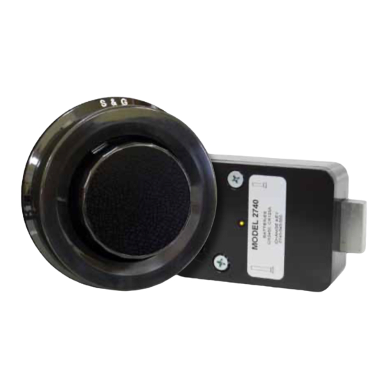
Model 2740 High Security Safe Lock
Mounting Considerations:
• This lock requires setup and adjustment with
the use of a setup module after installation. The
installation cannot be completed without the use
of a setup module. Setup modules are only issued
to S&G Certified Technicians who have sucessfully
completed specialized training on the 2740 lock.
• The Sargent & Greenleaf 2740 safe lock is
designed to use the same mounting screw
locations as common S&G mechanical and
electronic safe locks. In most instances it can
easily be mounted in place of these locks.
• The 2740 lock bolt is drilled and tapped to
accept an extension, if necessary. When attaching anything to the lock bolt,
make sure the end of the lock bolt (not the extension) can retract within 0.125 inch (3 mm) of being flush with the
end of the lock case.
• The 2740 accommodates right-hand, left-hand, vertical-up and vertical-down mounting applications. A single model
can be splined for any of these applications during the installation process.
• The dial ring diameter is approximately 3 ¾ inches, matching the diameter of the majority of S&G dial rings.
• Each 2740 lock and cover is configured to work together. If installing multiple locks, be very careful to avoid using
a cover with any lock other than the one with which it was shipped from S&G's factory.
• Each 2740 lock requires one CR2450 coin cell battery and one CR123A lithium camera-type battery. Any time
one battery is replaced, the other should be replaced. Fresh batteries should be included with your lock. If not, be
careful to avoid using partially drained batteries.
• Modifications to the lock are not recommended and will void the manufacturer's warranty.
• Personal information that can be directly related to a combination holder, such as a birth date, street number, or
phone number, should not be used in creating a lock code. Avoid combinations that could be easily guessed. Be
sure to change the combination from the factory setting 50-25-50 to one of your own choosing.
• The S&G 2740 is warranted against defects in materials and workmanship. This warranty applies only to locks
installed and set up by an S&G certified technician.
Sargent & Greenleaf, Inc.
A Wholly Owned Subsidiary of Stanley Security Solutions, Inc.
PO Box 930, Nicholasville, Kentucky 40340-0930 USA
Phone (859) 885-9411
Phone (800) 826-7652
FAX (859) 887-2057
FAX (800) 634-4843
Copyright
©
2010, Sargent & Greenleaf
page 1
Sargent & Greenleaf S.A.
9, chemin du Croset
1024 Ecublens, Switzerland
Phone +41-21 694 34 00
FAX +41-21 694 34 09
Document 630-745
Revised 7/22/2010
Advertisement
Table of Contents

Subscribe to Our Youtube Channel
Related Manuals for Sargent and Greenleaf 2740


Summary of Contents for Sargent and Greenleaf 2740
- Page 1 • The dial ring diameter is approximately 3 ¾ inches, matching the diameter of the majority of S&G dial rings. • Each 2740 lock and cover is configured to work together. If installing multiple locks, be very careful to avoid using a cover with any lock other than the one with which it was shipped from S&G’s factory.
- Page 2 Installation Notes The Sargent & Greenleaf model 2740 lock was designed to meet Federal Specification FF-L-2740A. It can be retrofit to most security containers currently in service. It is necessary to remove only the lock cover for installation. All other parts should remain in place as received from the manufacturer.
- Page 3 4. Slide the dial spring over the spindle hub at the base of the spindle. Place the metal dial washer on top of the spring, then the white washer on top of the metal washer, as shown in the photo to the right. 5.
- Page 4 10. With the dial spring and flat washer in place, insert the dial into the lock. Hold the drive cam in place, positioned for its gate (Figure 6) to receive the fence of the lever assembly, and thread the dial into the cam until the top of the dial is flush with the top surface of the dial ring (Figure 4, far right) or until the dial stops.
- Page 5 13. Install the two batteries in the underside of the cover (Figure 8). The circular coin cell battery goes in first, positive side up. Then the camera-type battery is inserted as shown. When the coin cell battery and then the main battery are installed, you will hear a beep. If you do not hear the beep, remove both batteries for one minute, then repeat the installation process.
- Page 6 16. Again, check to make sure the dial turns freely. 17. Place the self-adhesive orange label inside the safe or container, where it is readily visible when the door or locking drawer is open. For instance, the locking drawer’s inside cover is a good location. There is also a 5/8"...
Need help?
Do you have a question about the 2740 and is the answer not in the manual?
Questions and answers