Table of Contents
Advertisement
Installation and Combinatiion Changing Instructions
8500 Series MP Safe Locks
Models 8550 (Group 1) and 8560 (Group 1R)
NOTE: READ COMPLETE INSTRUCTIONS BEFORE INSTALLATION
These instructions should be followed when installing Sargent
These instructions should be followed when installing Sargent
& Greenleaf 8500 Series locks.
Caution: Lock mounting bedplate and dial ring mounting surfaces
Caution: Lock mounting bedplate and dial ring mounting surfaces
must be parallel. Dial ring center line must be precisely aligned
must be parallel. Dial ring center line must be precisely aligned
with lock spindle center line (see Figure 3).
Locate exact position you want for the lock on the mounting
plate. Using the template on the last page of these
instructions, drill and tap four holes for the attaching
screws (
⁄
X 20).
1
4
Using the template, drill a hole for the spindle through
the mounting plate. For applications requiring an optional
tube, the hole should be
without tubes, the hole should be
It is necessary to remove only the cover when attaching the lock. All other parts should remain in
It is necessary to remove only the cover when attaching the lock. All other parts should remain in
place as received from the factory.
INSTALLATION INSTRUCTIONS
1. Remove the lock cover. Place the lock bolt in the extended position and the accelerator spring in the
loaded position (Figure 1). CAUTION: Do not remove the drive cam.
Accelerator Spring in Released Position
Sargent & Greenleaf, Inc.
PO Box 930, Nicholasville, Kentucky 40356 USA
Phone (859) 885-9411
Phone (800) 826-7652
FAX (859) 887-2057
FAX (800) 634-4843
Copyright
©
2002, Sargent & Greenleaf, Inc.
⁄
'' diameter. For locks to be used
13
16
⁄
'' diameter.
1
2
Illustrations
Accelerator Spring in Loaded Position
Figure 1
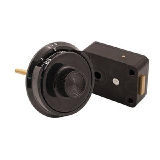
MP Lock
Torque Adjusting Gear
page 1
S G
Sargent & Greenleaf S.A.
9, chemin du Croset
1024 Ecublens, Switzerland
Phone 41-21-691-9583
FAX 41-21-691-5349
Document 630-674
Revision 1.1 (7/7/03)
Advertisement
Table of Contents

Related Manuals for Sargent and Greenleaf 8550


Summary of Contents for Sargent and Greenleaf 8550
- Page 1 Installation and Combinatiion Changing Instructions 8500 Series MP Safe Locks Models 8550 (Group 1) and 8560 (Group 1R) NOTE: READ COMPLETE INSTRUCTIONS BEFORE INSTALLATION These instructions should be followed when installing Sargent These instructions should be followed when installing Sargent &...
- Page 2 2. Mount the lock in place with four X 20 attaching screws (provided). ⁄ 3. Attach the dial ring by loosely installing the attaching screws to hold the dial ring in place for alignment. The dial ring opening index should be at the 12 o’clock center position. 4.
- Page 3 8. Tighten the dial ring screws. 9. Place a flat washer, the compression spring, and another flat washer over the spindle and into the recess at the dial hub (Figure 4). Figure 4 10. Insert the dial into the lock, but remember that you should not allow the cam to slide outward against the accelerator spring, possibly damaging it.
- Page 4 15. Turn the dial at least one complete revolution in either direction, then stop at 50. The accelerator spring should now be in the loaded position. 16. Hold the lock cover in place and push the dial in at 50. The accelerator spring should not release. If the accelerator spring does release, the spindle must be turned clockwise into the cam one revolution and the lock checked again, beginning at step 13.
- Page 5 TO LOCK Turn the dial counterclockwise (left) at least five complete revolutions for maximum security. COMBINATION CHANGING FROM 50 - 0 Make up a new combination, selecting three numbers of your own choosing. Do not set the third number of the combination between 90 and 99 or 0 and 10. This area is known as the forbidden zone. Adjacent combination numbers should be at least 5 numbers apart.
- Page 6 COMBINATION CHANGING FROM A SAMPLE COMBINATION OF 50 - 25 - 50 1. Turn the dial counterclockwise, stopping when 50 is aligned with the changing index the fourth time. 2. Turn the dial clockwise, stopping when 25 is aligned with the changing index the third time. 3.
- Page 7 4. Unscrew the dial and spindle assembly from the lock. Remove the drive cam. 5. Remove the Spirolox retainer from the top of the wheel post. ® 6. Remove the wheels and associated parts. Place them in sequence so they can be re-installed in the proper order.
- Page 8 ERRORS The most frequent error in the changing procedure is dialing the number to the wrong index. Occasionally all the numbers may be dialed to the opening index rather than the changing index. More often, dialing part of the combination to the changing index and part to the opening index occurs. As long as the door is open, the error is easily corrected.
Need help?
Do you have a question about the 8550 and is the answer not in the manual?
Questions and answers