Table of Contents
Advertisement
Quick Links
General Information
Your A-Series Lock was shipped with the keypad, keypad extension,
and cable disconnected. If your lock is not already assembled,
temporarily connect them now as shown in these instructions.
You should install fresh batteries in the keypad (S&G recommends
Duracell® alkaline batteries) and check the function of the lock prior to
installation by pressing 10101010# and observing the lock bolt retract,
then extend 6 seconds later. After this check, disconnect the cables
from the extension base and keypad by pulling on the connectors (NOT
on the cables themselves).
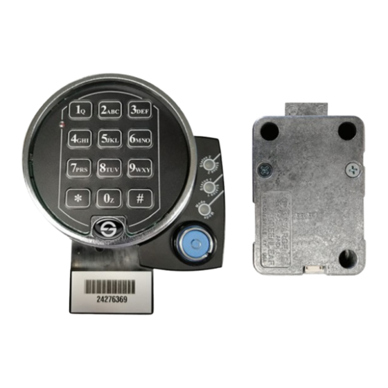
Item
Quantity
1
1
Lock body
2
1
Keypad
3
1
Keypad Base
4
1
Keypad Extension
5
1
Escutcheaon
6
1
Keypad with serial plate
7
1
Extension Cable
8
1
Keypad cable
9
1
Bolt Position Cable (BPI) / Door Switch
10
4
Keypad mounting screws (2 standard/2 metric)
11
6
Lock Mounting screws (3 standard/3 metric)
12
3
Lock serial number
3
7
10
Sargent and Greenleaf
Electronic Safe Lock Installation Instructions
Description
4
8
11
Model 6128/6129 A-Series
1
2
5
1
6
9
12
Revision 07/15/2021 L Document: 630-1051
Advertisement
Table of Contents

Related Manuals for Sargent and Greenleaf 6128 A Series


Summary of Contents for Sargent and Greenleaf 6128 A Series
- Page 1 Keypad Extension Escutcheaon Keypad with serial plate Extension Cable Keypad cable Bolt Position Cable (BPI) / Door Switch Keypad mounting screws (2 standard/2 metric) Lock Mounting screws (3 standard/3 metric) Lock serial number Sargent and Greenleaf Revision 07/15/2021 L Document: 630-1051...
- Page 2 Link connectors when ready for bolt extension Lock instation • UnPlug the 4 pin connector from the keypad. • UnPlug the 6 pin connector from the extension. The lock is now ready to be installed on the door. Sargent and Greenleaf Revision 07/15/2021 L Document: 630-1051...
- Page 3 The blue and grey wire is the secure loop. This closed circuit may be used in applications requiring switches or other devices to signal the lock that boltwork is thrown, the door is closed, or some other action has taken place. Sargent and Greenleaf Revision 07/15/2021 L Document: 630-1051...
- Page 4 Otherwise, there is risk of a lockout. After the plate is installed, once again check to make sure wires and cables are secured so that they will not come into contact with moving boltwork or anything else that can damage them. Sargent and Greenleaf Revision 07/15/2021 L Document: 630-1051...
- Page 5 *S&G has include a few zip ties to bundle up any lose cable. When utilizing the ties, try not to damage the cables and provide enough slack to allow for keypad removal. Sargent and Greenleaf Revision 07/15/2021 L Document: 630-1051...
- Page 6 *S&G has include a few zip ties to bundle up any lose cable. When utilizing the ties, try not to damage the cables and provide enough slack to allow for keypad removal. Sargent and Greenleaf Revision 07/15/2021 L Document: 630-1051...
- Page 7 Corporate Headquarters: One Security Drive | Nicholasville, Kentucky 40356 | 1-800-826-7652 . Except as otherwise noted, all trademarks in this data sheet are trademarks of Sargent and Greenleaf in the U.S. and elsewhere. ®denotes a trademark registered with the U.S. Patent and Trademark Office and/or other Trademark offices around the world.
Need help?
Do you have a question about the 6128 A Series and is the answer not in the manual?
Questions and answers