
Subscribe to Our Youtube Channel
Related Manuals for Leica DM4000 B


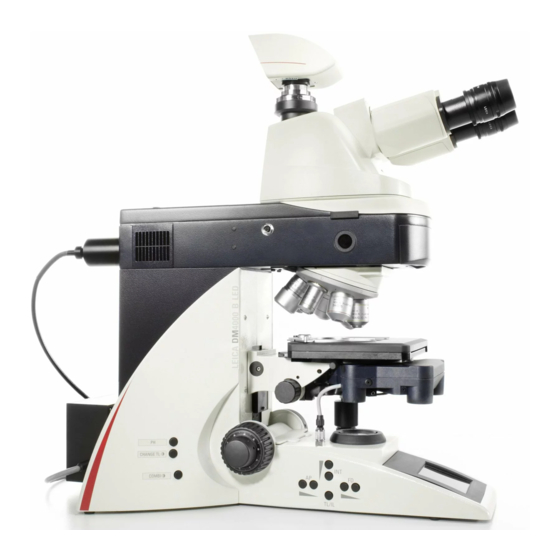
Summary of Contents for Leica DM4000 B
- Page 1 Leica DM4000 B Leica DM4000 M Leica DM4500 P Leica DM5000 B Operating Manual Bedienungsanleitung...
- Page 2 Published September 2007 by: Herausgegeben September 2007 von: Leica Microsystems CMS GmbH Ernst-Leitz-Straße D-35578 Wetzlar (Germany) Responsible for contents: Verantwortlich für den Inhalt: Dr. Jasna Roeth, Stefan Motyka (Marketing CM, Compound Microscopy, Product Management) (Marketing CM, Compound Microscopy, Produktmanagement) Holger Grasse (Safety Officer according to MPG §30)
- Page 3 Leica DM4000 B Leica DM4000 M Leica DM4500 P Leica DM5000 B Operating Manual...
- Page 4 (in whole or in part) by print, photocopy, microfilm or other method (including electronic systems) is not allowed without express written permission from Leica Microsystems CMS GmbH. The term "Windows" may appear in the following text without further identification. It is, however, a registered trademark of Microsoft Corpora- tion.
-
Page 5: Table Of Contents
7.1 Functional principle ........35 7.2 Switching on the unit ........ 38 Intended purpose of the microscope ..7.3 The display (DM4000 B/4500 B/4000 M/4500 P) ..39 Safety notes ..........7.4 The function keys ........40 3.1 General safety notes ......... - Page 6 Contents Contrast methods for 11. Troubleshooting ......... 74 Leica DM4000 B/DM4500 B/ DM4500 P/DM5000 B ........ 60 12. Care of the microscope ......77 9.1 Transmitted light ........60 12.1 Dust cover ........... 77 9.1.1 Bright field ......... 60 12.2 Cleaning ............77 9.1.2 Phase contrast ........
-
Page 7: Important Notes About This Manual
1. Important notes about this manual 1. Important notes about this manual Caution! This operating manual contains important in- This operating manual is an essential com- structions and information for the operational ponent of the microscope, and must be read safety and maintenance of the microscope and carefully before the microscope is assem- accessories. -
Page 8: Intended Purpose Of The Microscope
Leica Microsystems CMS GmbH. monitoring therapeutic measures. In such cases the declaration of conformity shall cease to be valid. -
Page 9: Safety Notes
EN 61010-2-101:2002 The responsible Leica affiliate or the main EN 61010-1:2001 plant in Wetzlar, Germany, must be consult- IEC 1010-1:2001 ed whenever the device is altered, modified... -
Page 10: Electrical Safety
3. Safety notes 3.2 Electrical safety ebq 100 supply unit* General specifications For indoor use only. Supply voltage: 90-250 V~ Leica CTR5000 electronics box (for DM5000 B) Frequency: 50-60 Hz For indoor use only. Power input: max. 155VA Supply voltage:... -
Page 11: Disposal
3. Safety notes 3.3 Disposal Caution! Once the product has reached the end of its ser- vice life, please contact Leica Service or Sales Never use any fuses as replacements other about disposal. than those of the types and the current rat- ings listed here. -
Page 12: Overview Of The Instrument
Leica DM5000 B Contrast methods • Transmitted light: • Transmitted light: DM4000 M: BF, DF, PH, ICT, DM4000 B: BF, DF, PH, Pol DM5000 B: and ICT (mot.) DM4500 P: BF, DF, PH, ICT, • Incident light: Fluorescent Pol (conoscopy) •... - Page 13 • Operating buttons on the stand for all motorized microscope functions • Additional variable multifunction keys • Focus wheels • LCD • DM5000 B with Leica SmartTouch Computer interface • USB2.0 Software tools • Leica Application Suite (LAS) for Windows 2000, XP, Vista •...
- Page 14 Specification Leica DM4000 B Leica DM4000 M Leica DM5000 B Leica DM4500 P Electronics box Only for the Leica DM5000 B: Leica CTR5000 Separate operating unit with a power supply for 100 W halogen lamps. See → p.10 (Electrical safety)
- Page 15 4. Overview of the instrument Fig. 1 Left side of the stand with the advanced AET22 ErgoTube Field diaphragm operating buttons Eyepiece Eyepiece tube Transmitted light / incident light switch 10 Aperture diaphragm operating buttons Tube Objective turret with objectives 11 Brightness adjustment buttons 12 Focus wheel with coarse and fine adjustment Specimen stage with specimen holder...
- Page 16 4. Overview of the instrument 19 18 Fig. 2 Right side of the stand with the advanced ErgoTube AET22 15 Lamp housing for incident light 16 Lamp housing for transmitted light 17 Transmitted light filter, optional 18 Transmitted light filter, optional 19 Variable function keys (preset at the factory) 20 x/y coaxial drive, adjustable height 21 Handwheel for fine focus...
-
Page 17: Unpacking The Microscope
• Specimen stage with stage bracket • Power cable and PC connecting cable Note: • CD with Leica Application Suite (LAS) soft- If at all possible, avoid touching the lens surfac- ware package es of the objectives. If fingerprints do appear on the glass surfaces, remove them with a soft •... - Page 18 5. Unpacking the microscope Installation location Transport Work with the microscope should be performed For shipping or transporting the microscope in a dust-free room, which is free of oil vapors and its accessory components, the original and other chemical vapors, as well as extreme packaging should be used.
-
Page 19: Assembling The Microscope
6. Assembly 6. Assembling the microscope 6.1 Specimen stage The microscope components are logically as- sembled in this order: Caution: • Specimen stage • Condenser with condenser head Never install objectives before assembling the • Tube stage. • Eyepieces • Objectives •... - Page 20 Note: Attachable mechanical stage* The attachable mechanical stage can be in- For thicker specimens (Leica DM4000 M) the stalled on the left, on the right or on the front stage can be set to a correspondingly lower level. (not pictured). The two clamping screws fas- ten it into place.
-
Page 21: Condenser
6. Assembly 6.2 Condenser • Screw the condenser head into the condenser. Note: The condenser must be centered before using • Using the condenser height adjuster (5.4), turn the microscope. the condenser holder (5.1) downward as far → Köhler illumination p. 41. as it will go. -
Page 22: Tube And Eyepieces
6. Assembly 6.3 Tube and eyepieces • The eyepieces are inserted into the eyepiece tubes on the tube. The tube is mounted on the stand either directly or with the use of intermediate modules. The • For the BDTP tube only: side clamping screw fastens it into place (9b.1). -
Page 23: Objectives
6. Assembly 6.4 Objectives 6.5 Light sources for the transmitted light axis The receptacles on the objective turrets are numbered (Fig. 11). Based on your equipment, Caution! the individual objectives have already been as- signed to specific positions at the factory. Ensure that the lamp housing has been dis- For details on the exact positions of the objec- connected from the power supply. - Page 24 6. Assembly • Insert the new 12 V 100 W lamp (13.1) with the • Place the lamp housing in the transmitted dust cover straight into the socket until it light lamp housing receptacle (14.2) and fas- stops. Be sure that the lamp is inserted ten it with the clamping screw on the side.
-
Page 25: Light Sources For The Incident Light Axis
6. Assembly 6.6 Light sources for the incident light axis Lamp housing 106/106 z This lamp housing is suitable for use with a 12 V 100 W halogen lamp or a variety of gas discharge Caution! lamps. Light sources pose a potential irradiation Caution! risk (glare,... - Page 26 6. Assembly Inserting the 12 V 100W halogen bulb into the • Insert the lamp mount, with the burner in- 106/106 z lamp housing stalled, into the lamp housing and tighten it with the screws (16.8). • Unscrew the fastening screws of the cover and flip the cover up (16.1).
- Page 27 6. Assembly Inserting gas discharge lamps (Hg and Xe) into the 106/106z lamp housing Hg and Xe lamps are powered by separate sup- ply units. Please also read the separate instruction manu- al provided with these supply units. The following gas discharge lamps may be used and require different power supplies and lamp mounts (Fig.
- Page 28 6. Assembly • To open the 106 z lamp housing, unscrew the fastening screws on the cover. Caution! • Remove the transport anchor (red plastic rod Hg 50 burner: in place of the burner) in the lamp mount. To After installation, the labeling must be up- do so, remove the lower clamp (19.1).
- Page 29 6. Assembly • Insert the lamp mount, with the burner in- stalled, into the lamp housing and tighten it with the screws (20.8). • Close the lamp housing and retighten the fas- Fig. 20 106/106 z lamp housing (on the side, open) tening screws.
-
Page 30: Equipping The Incident Light Turret Disk
6. Assembly 6.7 Equipping the incident light turret disk Fig. 23 Filter cube, Fig. 24 Filter cube, front side back side The positions in the turret disk are numbered. Depending on how they are equipped, the indi- vidual filter and/or reflector cubes are set in pre-assigned positions at the factory. -
Page 31: Polarizer And Analyzer
6. Assembly 6.8 Polarizer and analyzer Fig. 27 Assembly of the ICT/P transmitted light polarizer Clamping screw Transmitted light polarizer: ICT/P • Using the left clamping screw, fasten the ICT/P transmitted light polarizer to the underside of the condenser holder (Fig. 27). •... -
Page 32: Dic Prisms
• Insert the analyzer into the receptacle until it latches in place (Fig. 30). • In the Leica DM5000 B microscope, the DIC prisms are already installed in the DIC disk above the objective turret (Fig. 68). -
Page 33: Optional Accessories
6. Assembly 6.10 Optional accessories Booster lens / excitation manager ErgoModule • Insert the filter slide into the front receptacle on the right side of the stand (Fig. 32.1, 33.1). For raising the eye level of the tube opening, the ErgoModule may be used. -
Page 34: Connection To The Power Supply
(Fig. 34.2). • Connect terminals (35.1) and (36.1) to the 25-pin microscope cable. Fig. 34 Rear side of the Leica DM4000 B/M stand Power switch • Connect the electronics box to the power sup- Power supply ply using the power cable (35.2). -
Page 35: Startup
7. Startup 7. Startup 7.1 Functional principle The microscope's most important functions may be easily accessed using function keys. • The microscope may be switched between various contrast methods by pressing a button. • The microscope recognizes the selected objective and associated contrast method. There- fore, the values for intensity (INT), aperture diaphragm (AP) and field diaphragm (FD) are always set correctly. - Page 36 7. Startup Possible assignments for the function keys For Leica DM4000 B/DM5000 B: Function button Function Bright field transmitted light Phase contrast transmitted light Interference contrast, transmitted light Dark field transmitted light Polarization transmitted light CHANGE TL Switches through all transmitted light contrast methods INT ↑...
- Page 37 7. Startup For Leica DM4000 M/DM4500 P: Function button Function Bright field incident light Interference contrast, incident light Dark field incident light Polarization incident light CHANGE RL Switches through all incident light contrast methods INT ↑ Increases the brightness (incident light) INT ↓...
-
Page 38: Switching On The Unit
Components such as diaphragms, condensers, Note: light and phase rings have been pre-centered at The Leica DM4500 P microscope is equipped at the factory. It may be necessary to correct the the factory with an encoded conoscopy module. centering after the microscope has been trans- •... -
Page 39: The Display (Dm4000 B/4500 B/4000 M/4500 P)
7. Startup 7.3 The display (Leica DM4000 B/ Light intensity DM4000 M/DM4500 P) The screen displays the microscope’s current The current brightness setting is graphically de- settings. The content of the display depends on picted by a beam. In addition, the light intensity the features of the individual microscope. -
Page 40: The Function Keys
→ p. 36f. Note: Fig. 38 Fixed function keys (left side of stand) The Leica Application Suite (LAS) module "Con- Toggling between transmitted light / incident light figuration" is required for changing the key as- Aperture diaphragm signments. -
Page 41: Köhler Illumination
7. Startup 7.5 Köhler illumination • Press the BF button to activate the bright field contrast method (one of the variable function 7.5.1 Transmitted light keys behind the focus wheel). Suitable aperture and field diaphragm values "TL BF" appears in the first line of the display. have been preset for each objective. -
Page 42: Incident Light
• Select the bright field contrast method by pressing the IL-BF button (DM4000 M) or se- lect fluorescence by pressing the FLUO button (DM4000 B, DM5000 B). These functions can be assigned to the vari- able function keys on the stand. - Page 43 7. Startup Adjusting the field diaphragm Adjusting the aperture diaphragm (for DM4000 M and DM4500 P only) • Close the field diaphragm with the FD button (38.4) or manually until the edge of the dia- • Remove one eyepiece (e.g. right). phragm (round or rectangular) appears in the field of view.
-
Page 44: Checking The Phase Contrast Rings
7. Startup 7.6 Checking the phase contrast rings • In the place of an eyepiece, insert the focus- ing telescope (Fig. 43) into the observation If your microscope is equipped for the use of tube. phase contrast, the light rings that fit the objec- tives are built into the condenser. -
Page 45: Setting The Motorized Polarizer (Dm4500 P/Dm5000 B)
(DM4500 P/DM5000 B) condenser. • Select the POL method (one of the variable function keys on the stand or on the Leica- • Turn the centering key until the dark ring Screen). (phase ring in the objective) is congruent with the slightly narrower bright ring (light ring in •... - Page 46 • Activate the incident-light axis with the TL/IL function button. FLUO (Leica DM4000 B/ On the left side of the microscope, there is an DM5000 B) or IL (Leica DM4000 M/DM4500 P) adjustment window (1.14, p. 15) for mapping the appears in the display.
- Page 47 7. Startup Centering the 12 V 100 W halogen bulb Fig. 47 Direct lamp filament image focused, but not centered • In the adjustment window, you see the direct (in reality, the image is less focused) filament image and the mirror image, which as a rule are shifted together.
- Page 48 7. Startup Centering the Hg 50 W Mercury Lamp Fig. 50 Direct arc image focused but not centered (in reality, the image is less focused) • The adjustment window shows the direct im- age of the arc and its mirror image. These are generally not in alignment with one another.
- Page 49 7. Startup Centering the Hg 100 W and Xe 75 W Fig. 53 Direct arc image focused but not centered (in reality, the image is less focused) mercury lamps • The adjustment window shows the direct im- age of the arc and its mirror image. These are generally not in alignment with one another.
- Page 50 7. Startup Caution! In older lamps, the structure of the arc is no longer clearly recognizable. The image is then more like that of a HG 50 lamp. The im- age and mirror image can no longer be su- perimposed exactly. In this case, align both images.
-
Page 51: Operation
8. Operation 8. Operation 8.1 Switching on the unit 8.2 Stages and object displacement When using a gas discharge lamp, the external supply unit must be turned on separately (56.1). Lengthening the coaxial drive Switch on the microscope or the CTR5000 at the •... - Page 52 8. Operation Rotating the stage 45°click stop: • Screw in the rotary knob (59a.5) until you can The swivel range of the rotating stages is 0° - 110°. feel it starting to resist. • Rotate the stage to loosen the locking screw •...
-
Page 53: Focusing
8. Operation 8.3 Focusing 8.4 Tubes There is a focus wheel on the left side of the stand for coarse and fine focus adjustment (Fig. 59b). Note: Close any unused tube openings, as otherwise On the right side of the stand, there is also a fo- stray light can interfere with observation. - Page 54 8. Operation Adjusting the viewing angle BDT25+ tube: The light division is set manually by pulling out a • For the AET22 and EDT22 ergo tubes, the control bar. viewing angle can be adjusted by tilting the binocular eyepiece in the range of 5° – 32° Control Bar Observation Photo...
-
Page 55: Eyepieces
8. Operation 8.5 Eyepieces 8.6 Objectives The objectives are moved into the beam path manually. Be sure that the turret locks into Note: place. The eyepiece’s aperture protector must be re- The positions of the objectives in the objective moved or folded back, during microscopy while turret have been specified at the factory and wearing glasses. - Page 56 8. Operation For lockable immersion objectives: Objective centering * (DM4500 P) • Lock these by pushing the front part upwards until it stops (approx. 2 mm). Caution: • Then, after a gentle turning motion to the When changing the objective, the centering key right, the objective is locked (Fig.
- Page 57 8. Operation • Switch off the analyzer, the 1.6x tube lens and Method II (Fig. 65) the Bertrand lens. • Move the marked specimen position (65a) into • Reduce the aperture diaphragm so that it is the center of the M cross-hairs. very small.
-
Page 58: Magnification Changer
8. Operation 8.7 Magnification changer 8.8 HC P 1x/1.6x tube optics with Bertrand lens (encoded) Optionally, a coded magnification changer can be used, which is manually operated. These optics were developed especially for po- On the knurled ring, the following magnification larizing microscopy;... -
Page 59: Light Sources
8. Operation 8.9 Light sources 8.10 Aperture diaphragm and field diaphragm • Adjust the brightness using the function keys Both diaphragms have been set to suitable val- (66.5). The INT function buttons are always ues for the current objective and contrast meth- assigned to the currently active transmitted od at the factory. -
Page 60: Contrast Methods For Leica Dm4000 B/Dm4500 B/ Dm4500 P/Dm5000 B
9. Contrast methods for Leica DM4000 B/DM4500 P/DM5000 B 9. Contrast methods for Leica DM4000 B/DM4500 P/DM5000 B 9.1 Transmitted light 9.1.2 Phase contrast (TL) 9.1.1 Bright field (TL) • Switch to the transmitted light axis (TL) by pushing the TL/IL function key. -
Page 61: Dark Field
9. Contrast methods for Leica DM4000 B/DM4500 P/DM5000 B 9.1.3 Dark field (TL) 9.1.4 Polarization (TL) • Switch to the transmitted light axis (TL) by • Switch to the transmitted light axis (TL) by pushing the TL/IL function key. pushing the TL/IL function key. -
Page 62: Dm4500 P - Examinations In Polarized Transmitted Light
9. Contrast methods for Leica DM4000 B/DM4500 P/DM5000 B 9.1.4.2 DM4500 P - examinations Crossed polarizers in polarized transmitted light According to DIN and ISO ratings the run of the One polarizer only vibration directions corresponds to the table on p. - Page 63 9. Contrast methods for Leica DM4000 B/DM4500 P/DM5000 B Simple overview observations Circular polarization • Place the transmitted light specimen on the When the specimen stage is rotated, birefrin- polarizer. gent specimens show 4 extinction positions. When a larger number of birefringent speci- •...
- Page 64 9. Contrast methods for Leica DM4000 B/DM4500 P/DM5000 B • Insert the λ/4 plate (69.5) into the tube slot. For HC P tube optics, use an iris diaphragm to mask out the measuring points. • Insert the λ/4 plate (69.1) into the receptacle...
- Page 65 9. Contrast methods for Leica DM4000 B/DM4500 P/DM5000 B ence; rather, it provides only the difference over Because the interference images appear in the the entire wavelength or over a multiple of the eyepoint, they are not visible during typical wavelength.
- Page 66 9. Contrast methods for Leica DM4000 B/DM4500 P/DM5000 B • Insert the Bertrand lens (Fig. 70B) and focus it Even if only one of the optical axes is within the by rotating the operating button until the inter- observer’s direction of sight, the optical charac- ference image or the circular diffuse edge of ter can usually be identified.
- Page 67 9. Contrast methods for Leica DM4000 B/DM4500 P/DM5000 B Biaxial, positive crystals: Possible faults When the compensator is activated, the move- The polarizers have been damaged (discolored) ment of the interference bands proceeds from by strong light sources or they are heavily the convex side to the concave side of the soiled.
-
Page 68: Motorized Method
9.1.4.4 Combined methods • Select the DIC contrast method. • For the Leica DM4000 B, DM4500 P and Leica Do so by pressing the DIC variable key. DM5000 B microscopes, it is possible to com- Or by pressing the variable button. -
Page 69: Dm5000 B
9. Contrast methods for Leica DM4000 B/DM4500 P/DM5000 B • Insert the analyzer on the left side of the stand Alternatively: up to the click stop (fig. 73). • Manually rotate polarizer underside of the condenser into the beam • Then insert the objective prism slider into the path (Fig. -
Page 70: Fluorescence
9. Contrast methods for Leica DM4000 B/DM4500 P/DM5000 B • For fine adjustment, use the knurled wheel Cube or Cube above the objective turret. 9.2 Fluorescence • Switch to the fluorescence axis / fluores- • Bring the image into focus using the focus... -
Page 71: Contrast Methods For Leica Dm4000 M
10. Contrast methods for Leica DM4000 M 10. Contrast methods for Leica DM4000 M 10.1 Incident light 10.1.2 Dark field (IL) 10.1.1 Bright field (IL) • Switch to the incident light axis (IL) by push- ing the TL/IL function key. -
Page 72: Polarization
10. Contrast methods for Leica DM4000 M 10.1.3 Polarization (IL) Automatic procedure: • Switch to the incident light axis (IL) by push- • The ICR filter cube is automatically brought ing the TL/IL function key. into the beam path. • Select the POL (polarization) contrast method Manual procedure: by pressing the variable button POL. -
Page 73: Interference Contrast
10. Contrast methods for Leica DM4000 M 10.1.4 Interference contrast (RL) 10.2 Transmitted light • Switch to the incident light axis (IL) by push- 10.2.1 Bright field (TL) ing the TL/IL function key. • Switch to the transmitted light axis (TL) by pushing the TL/IL function key. -
Page 74: Troubleshooting
11. Troubleshooting 11. Troubleshooting Problem Cause/remedy Stand The microscope does not respond. Ensure that the AC outlet has power. Make sure that the microscope is connected to the power supply. Check the cable connections. Inform Service and have the supply unit fuse checked. - Page 75 11. Troubleshooting Problem Cause/remedy Bright field The specimen can not be brought into focus. Use the correct immersion medium. Lay the specimen with the cover glass toward the top. Make sure that the cover glass thickness is correct and that it meets the specifications on the objective.
- Page 76 11. Troubleshooting Problem Cause/remedy Polarization No polarization contrast is possible. Bring the polarizer and analyzer into cross po- sition until they reach maximum darkness (without specimen).(→ p. 61ff, 72). The embedding material for transmitted light specimen is birefringent. The image is insufficient. Polarizers can be damaged by strong light sources.
-
Page 77: Care Of The Microscope
12. Care of the microscope 12. Care of the microscope 12.2 Cleaning Caution! Caution: Unplug the power supply before performing cleaning and maintenance work! Residual fiber and dust can create unwanted Protect electrical components from moisture! background fluorescence. Microscopes in warm and warm-damp climatic Cleaning coated parts zones require special care in order to prevent Dust and loose dirt particles can be removed... -
Page 78: Handling Acids And Bases
Caution: faces, the objectives must be sent to your Be absolutely certain to prevent the optics Leica subsidiary for repair. We also advise and mechanical parts from coming into con- against cleaning the inside surfaces of the tact with these chemicals. -
Page 79: Essential Wear And Spare Parts
13. Essential wear and spare parts 13. Essential wear and spare parts Order No. Material No. Name Used for Replacement lamps 11 500 974 Halogen bulb 12 V 100 W 107/2 lamp housing 11 500 137 High-pressure mercury burner 106 z lamp housing 11 500 138 High-pressure mercury burner 100W 106 z lamp housing... -
Page 80: Abbreviations And Pictograms
14. Abbreviations and pictograms 14. Abbreviations and pictograms Contrast method Magnification Light intensity / diaphragms Light division in the motorized tube ↑ Transmitted light shutter is open ↑ Transmitted light shutter is closed ↓ Incident light shutter is open ↓ Incident light shutter is closed Advanced ergo tube Aperture diaphragm... -
Page 81: Index
Specimen holder 19 Disposal 11 receptacle 24, 26, 29 Specimen stage 19 LAS software package 13, 17 ebq 100 supply unit 10, 29, 51 Leica CTR5000 electronics Transmitted light / incident Electrical safety 10 box 10, 34 light toggle 15 ErgoModule 33... -
Page 82: Eu Declaration Of Conformity
16. EU Declaration of Conformity 16. EU Declaration of Conformity Download: http://www.light-microscopy.com/down_ce-declaration_DM4000b http://www.light-microscopy.com/down_ce-declaration_DM4000m http://www.light-microscopy.com/down_ce-declaration_DM4500p http://www.light-microscopy.com/down_ce-declaration_DM5000b...
Need help?
Do you have a question about the DM4000 B and is the answer not in the manual?
Questions and answers