Table of Contents
Advertisement
Quick Links
Advertisement
Table of Contents

Related Manuals for Leica DM IRB


Summary of Contents for Leica DM IRB
- Page 1 Leica DM IRB Instructions...
- Page 2 Issued in 1998 by: Leica Microsystems Wetzlar GmbH Ernst-Leitz-Strasse D-35578 Wetzlar (Germany) Responsible for contents: Marketing MQM, product management, Tel. +49 (0) 64 41-29 25 19 Fax +49 (0) 64 41-29 22 55...
- Page 3 Leica DM IRB Instructions...
- Page 4 – in full or in part – by printing, photostat, microfilm or other techniques, in- cluding electronic systems, is only permitted subject to the express written consent of Leica Microsystems Wetzlar GmbH. The information contained in the following documentation represents the latest stage of technology and knowledge.
-
Page 5: Table Of Contents
Unpacking ............16 Inserting the eyepieces/graticules ....37 Inserting the photoeyepieces ......38 Installation ............16 Screwing objectives in and out ......38 Assembling the stages, the plane stage and object guide ..........38 The E version DM IRB/E ........41... - Page 6 Contents Learn mode ............43 Operation Installing the objective prisms ......43 of transmitted light interference contrast ..78 Learning the IC objective prisms ..... 43 Installing the objectives ........44 Operation of incident light fluorescence ..81 Parfocality ............47 Dry objectives ............
-
Page 7: Important Notes On This Manual
Important notes on this manual This manual is an integral part of the Leica The manual is multi-lingual. Due to the spiral DM IRB microscope and must be read carefully binding you can turn the language version you before you start using the microscope. -
Page 8: General Safety Information
The mains plug must only be inserted into a consult the Leica agency for your area or the grounded outlet. main factory in Wetzlar! - Page 9 n. b.: n. b.: The electric accessories of the microscope Protect the microscope from major tem- are not waterproof. If water gets inside them, perature fluctuations. These may lead to it may cause electrical shock. condensation which can damage the electric Do not put the microscope and its acces- and optical components.
-
Page 10: Intended Application
Intended application The new DM IRB is the logical further development successful inverted research microscope from Leica. It is used for examinations of cells and tissue, for micromanipulation and microinjection tech- niques all the way through to microdissection or confocal microscopy. The DM IRB has universal... -
Page 11: The Microscope And Its Components
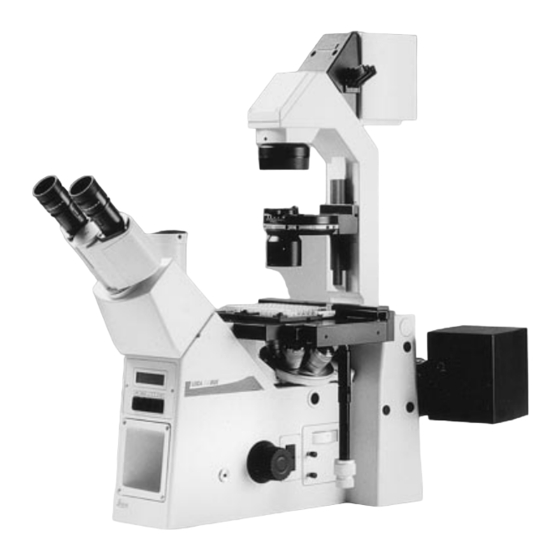
The microscope and its components Key subassemblies The following views of the whole microscope show and name important subassemblies of the microscope and its accessories. Fig. 1 – 2 1 Binocular phototube, 2 Eyepiece adapter tube, 3 Eyepieces, 4 Tube mount (tube change interface), 5 Tube port for photo/TV connection, 6 Beamsplitter switch, 7 Mains switch, 8 Brightness adjustment, 9 Lateral TV port, 10 Coaxial coarse and fine drive, 11 Fluorescence module, 12 ICT prism adjustment, 13 Sextuple objective nosepiece, 14 Centring buttons for incident light field diaphragm, 15 Field diaphragm adjustment, 16 Filters, 17 Aperture diaphragm adjustment, 18 Lamphousing mount (or... -
Page 12: Stands
The stand with bottom port cannot be equipped The stand with an SLR front port. This variant is only There are 5 basic versions of the DM IRB stand, produced at a customer’s specific request. which allow over 50 microscope variants to be configured. -
Page 13: Brightness Adjustment
Brightness adjustment Aperture diaphragm A 12 V 100 W transformer is built into the stand aperture diaphragm determines for stepless regulation of brightness with the resolution, field depth and contrast of the brightness control. microscope image. The best resolution is achieved when the apertures of the objectives Coarse and fine control and the condenser are roughly the same. -
Page 14: Specimen Stages And Accessories
A variety of lamphousings are offered for the All microscope objectives from magnification DM IRB (for halogen, mercury or xenon lamps). 2.5x to 100x can be used. All objectives from the The description and area of application can be DM L and DM R range with 25 mm thread are found in the operation section of this manual. -
Page 15: Installation Site
Installation site The microscope should be used in a dust-free room which is free of oil and chemical fumes n. b.: and extreme humidity. Also, the workplace should not be exposed to major temperature Lamphousings* and power units* must be fluctuations, direct sunlight or vibrations. -
Page 16: Unpacking
Please compare the delivery carefully with the transport and packing material. packing note, delivery note or invoice. We ● Put the basic DM IRB stand on a desk which strongly recommend that you keep a copy of has enough room for it. -
Page 17: Assembly
Installation and assembly of the microscope should preferably be carried out together with a Wipe off the interface surface (4.3) with a dry member of Leica sales or service staff. cloth. Tilt the illumination column (4.1) slightly to Only a few ordinary screwdrivers are required the back and insert so that the pin (4.2) engages... -
Page 18: Assembly Of Condensers
“Technical description”. protection filter is an integral part of the All condensers of the Leica DM IRB are transmitted light illumination column. The halo- equipped with a 6-position rotating disc (6.2 and gen lamp is preassembled. - Page 19 Insert the light rings for Phaco (identified by the – Using the centring keys, screw the centring code numbers 0, 1, 2, 3 and the intercept screws back in until they no longer protrude distance S of the corresponding condenser top, over the outer edge of the disc.
- Page 20 Fig. 8 Condenser 0.53 S23 1 Condenser base, 2 Condenser top 0.53 S23 (inter- changeable), 3 Condenser disc, 4 Aperture diaphragm, 5 Filter holder, 6 Dovetail guide Fig. 9 Condenser tops for condenser base (8.1) 1 Condenser top 0.53 S23, 2 Condenser top 0.90 S1, 3 Condenser top P 1.40 OIL S1, 4 Spacer ring for assembling 9.2 and 9.3 Fig.
-
Page 21: Assembly Of Ic Condenser Prisms
– Using the centring keys, screw the centring Assembly of IC condenser prisms screws back in until they no longer protrude The IC condenser prisms are assembled at the over the outer edge of the disc. The prism is factory. The following steps are only necessary adjusted with the left centring screw only (see in case of a retrofit: operation of ICT). -
Page 22: Condenser Top
Condenser top Assembly of the condensers to the illumination column The base and top of condenser 0.30 S70 form a self-contained unit (Fig. 6). Condenser 0.30 S70 The condenser top 0.30 S70 (13.4) cannot be Tilt the TL illumination column to the back (13.1). used with the condenser base (8.1). -
Page 23: Condenser 0.53 S23 And 0.90 S1
Condensers 0.53 S23 and 0.90 S1 With the illumination column tilted to the back, insert the condenser holder (15.4) into the dovetail guide of the illumination column from below (15.2). The condenser height adjustment should point to the left. Adjust the height of the condenser holder until its upper edge coincides with the condenser height marking S23 or S1 on the illumination column (16.1), depending on the... -
Page 24: Assembly Of Field Diaphragm
Assembly of field diaphragm Assembly of filters and filter holder To enable Koehler illumination when using The Leica DM IRB is equipped with a holder with condensers 0.53 S23 and 0.90 S1, a field spaces for 3 filters with 40 mm diameter. -
Page 25: Ic Module And Ic Objective Prisms
Assembling the ICT objective prisms Remove the front cover (22.2) under the objective nosepiece (23.1) after slackening the Assembling the IC module and IC objective Allen screws (22.4). prisms Insert the IC prism disc (22.1) in the mount and The IC prism disc with the IC prisms ordered by tighten with the two Allen screws. -
Page 26: Differences Between Prisms D And D1
Differences between prism D and D1 Inserting the analyser Prism D is the standard prism with greater Remove the blind slide and insert the analyser shearing and therefore higher detection sensi- (24.2) from the left as far as the 1 clickstop. -
Page 27: Inserting The Fluorescence Module
Inserting the fluorescence module Assembly of the lamp mount, mirror housing, lamphousing, illumination telescope The fluorescence module (Fig. 26) is part of the fluorescence stand, but is also available as a 1. Insert the lamp mount or mirror housing in retrofit kit. - Page 28 4. Connect the lamp plug to the connecting n. b.: socket in the stand (28.3). 5. Insert light filters, 50 mm Ø into the 2 spaces Connect the appliance cable to the mains in the lamphousing mounts (29.4). socket on the microscope stand (28.4)! Fig.
-
Page 29: Assembling And Exchanging Incident Light Lamps
Assembling and exchanging incident light Lamphousing 107 L lamps Slacken the fixing screw on the cover and lift off Exchanging the 12 V 100 W halogen lamp: the cover (Fig. 32a and 32b). Move the collector to the front and pull the defect 12 V 100 W lamp out of the base towards the front. -
Page 30: Lamphousing 106 Z L
Lamphousing 106 z L n. b.: Slacken the fixing screw on the lid (33.10). Pull the cut-out plug slightly out of the socket and flip up lid (33.11; 33.1). It is important to leave the protective cover Move the collector to the front and lift the defect on the lamp until it is in position. -
Page 31: Assembling And Exchanging Hg And Xe Lamps
Assembling and exchanging incident light Lamphousing 106 z L lamps Besides the halogen lamp, the following gas Assembling and exchanging Hg and Xe lamps discharge lamps can be used, which each require different lamp holders (Fig. 35) and Power units: power units: Hg and Xe lamps are powered by separate Type... - Page 32 Always insert the burner so that n. b.: n. b.: It is extremely important to heed the follow- ing advice! 1. the lettering is upright after insertion (dif- Always disconnect the power unit from the ferent diameters of the metal base for the mains before assembling the lamphousing Hg 100 and Xe 75 burners ensure that these 106 z.
-
Page 33: Assembly Of The Tubes And Tube Adapter Ir/R
Eyepiece diameter 30 mm for HL PLAN 10x/20 or 22 eyepieces. Eyepieces with larger field of view numbers are not recommended for use on the DM IRB. The tube adapter IR HC is mounted on the tube Fig. 36 Lamphousing 106 z L with Hg 100 W lamp... - Page 34 100 % vis., 100 % photo or 50 %/50 %. screw. The following tubes from the Leica DM R range Fig. 37 HCI B22, binocular tube with 45 viewing angle, field are also adaptable: of view up to 22 mm, eyepiece diameter 30 mm for HC PLAN Bino HC BSA 25 (42.1)
- Page 35 1 Tube adapter R/IR HC, 2 Clamp screw the adapter, 6 Photo/TV port Fig. 42 Leica DM R HC tubes 1 HC BSA 25, 2 HC FSA 25 P + PR, 3 Beamsplitter switch rod, 4 Mount for photo adapter tube, 5 Clamp for photo adapter Fig.
-
Page 36: Adaption Of The Slide Overlay Device And The Macro Dual System
Adaption of the slide overlay device and the macro dual system With the Leica DM IRB inverted microscope, the slide overlay and macro devices can only be adapted onto the FSA 25 PE tube. This tube has a side flange (44.1) for mounting the reflection optics. -
Page 37: Inserting The Eyepieces/Graticules
Screw the reflection optics (46.3) to the tube Important! flange with the coupling ring (46.2). Align the macro adapter (46.5) to the macro dual zoom Be very careful to keep the optical surfaces and secure with the screw ring (46.6). Screw the clean. -
Page 38: Inserting The Photoeyepieces
A constantly updated optics sheet outlines the adapting photo and video equipment. current range of objectives that can be used on the DM IRB/E. Ask your Leica agency for a copy. Screwing objectives in and out Assembling the stages, the plane stage and... - Page 39 3-plate x/y stage To assemble the square insert plate: The 3-plate x/y stage no. 19, size 247 x 230 mm, 1. Insert the corner of the insert plate that is x-y adjustment range 60 x 40 mm, is delivered in marked red (50.5) at an angle from above into separate packaging and assembled as follows: the corner of the stage that is also marked...
- Page 40 Only screw the screws in lightly, as the rotary stage first has to be pressed into If you have a DM IRB/E model (i. e. the electronic the centre. This is done by inserting the version), you have to set up the system.
-
Page 41: The E Version Dm Irb/E
DM IRB/E microscope themselves, a free Features of the Leica DM IRB/E software development kit called “Leica SDK“ is The Leica DM IRB/E offers the following addi- available for Windows 3.11, Windows 95 and tional functions: Windows NT on request. - Page 42 Assembly and initial installation If necessary, delete them by sustaining the rele- vant keys ( , Fig. 53b) for longer than The assembly of the individual components, 1 sec. Using the lower focus key, behind the such as transmitted light illumination column, handwheel on the right, move the nosepiece to condenser, etc.
-
Page 43: Learn Mode
The objective nosepiece rotates through 180 so interference contrast, refer to the instructions that the current objective is in the most on page 16 of the DM IRB manual. accessible position (furthest to the right on the outside). Learning the IC objective prisms (IC turret) This function also serves for cleaning, assem- bling, immersing, etc. -
Page 44: Installing The Objectives
Turn the IC turret (situated under the objective Installing the objectives nosepiece) until it clicks into the brightfield Select the “Objectives” option in the Learn position (H). mode (OBJ) by pressing the “CHANGE” key; the Operate the focus handwheel until the letter H “OBJ”... - Page 45 Now screw the objective with the lowest Display: IC objective prism magnification into the nosepiece opening which By pressing the “CHANGE” key, select the is furthest to the right. display field for the IC objective prism. Display: Objective magnification By turning the focus handwheel, select the Ob j e c t i v e 1 : number in the electronic display that corre- 5xPHO...
- Page 46 To learn further objectives: Operating modes: Dry/Immersion Select objective no. 2 with the upper objective To ensure simple yet safe objective change, the nosepiece key. Screw the objective with the objectives have to be classified in one of the next highest magnification into the nosepiece following three categories: opening which is now furthest to the right.
-
Page 47: Parfocality
Parfocality Oil immersion objectives Select the “Parfocality” option (“PARF”) in the Once the parfocality has been learnt for all the Learn mode by pressing the “CHANGE” key; the dry objectives it can be done for the immersion “PARF” option now flashes. objectives. -
Page 48: Individual User Adjustments
Individual user adjustments Z-drive Objective Nosepiece move- keys keys ment when the Chosen function Select the option “L/R” in the Learn mode by right handwheel is turned clockwise pressing the “CHANGE” key and confirm your O b j e c t . < > F o c u s choice by pressing the “LEARN”... -
Page 49: Installing The Fluorescence Filter Cube
Installing the fluorescence filter cube Learning other filters: Select the next filter cube position by pressing Select the “FLUO” option in the Learn mode by one of the “FLUO” keys on the control panel of pressing the “CHANGE” key. Confirm by press- the FLUO module. -
Page 50: Motorized Objective Nosepiece
Motorized objective nosepiece The upper key is pressed to increase the magnification, the lower key to decrease the The electronic nosepiece control allows easy magnification. Short pressure on the key and safe change of the objective magnification. switches next lower higher Objectives are changed with 2 push buttons magnification. -
Page 51: Operating Modes
DRY and IMMERSION Contamination of the dry objectives is prevented by the fact that the objective nosepiece is The Leica DM IRB microscope is equipped with always lowered before objectives are changed. a switch function between the operating modes “Dry” and “Immmersion” (IMM) to ensure When switching from one operating mode to the straightforward, error-free operation. -
Page 52: Automatic Lowering Of The Objective Nosepiece
The procedure for switching to the Dry mode is Automatic lowering of the objective nosepiece analogous: In order to be able to operate the objective Again, press the keys “lower z position” changing keys easily and without touching the and “focus position” on the control panel stage in situations where space is difficult, e.g. -
Page 53: Brightness Adjustment
Brightness adjustment Instead of a potentiometer, Leica DM IRB/E The lamp intensity is adjusted by rotating an microscopes are equipped with an incremental adjustment wheel on the left side of the transducer for brightness adjustment. This microscope. If you hadn’t already switched to... -
Page 54: Electronic Focus
Electronic focus The electronic focus offers the user the follow- The controls of the electronic focus are: ing advantages: – The focusing handwheels, conventionally – Extremely sensitive focusing, especially for positioned on both sides of the microscope. high magnifications. – Two keys (focus keys) for fast lowering of the –... - Page 55 – Key for defining the “lower Z position”. Coded IC objective prisms (option) Pressing the key for longer than 1 sec. deletes The objective IC prisms are arranged on a turret the threshold; another press of the key for underneath the objective nosepiece. To facili- longer than 1 sec.
- Page 56 Motorised fluorescence filter cube change Three keys are used for operation: (option) A control panel is connected to the Leica DM IRB for motorised filter cube change. Mot. filter cube module Shutter filter module F-bus F-bus Mains RS 232 control F-bus...
- Page 57 Control unit* When using a Leica DM IRB microscope, the unit must be powered by an external power unit. An electronic control unit can be connected for The switch on the back of the unit must the remote control of individual microscope...
- Page 58 Filter FILTER ((in preparation) Lamp LAMP Condenser COND function not possible on Field diaphragm FIELD Leica DM IRB/E Aperture diaphragm Objective change Incident light fluroescence axis FLUOR Z drive FOCUS x-y stage Footswitch FOOT Several keys are allocated to each component. These are grouped together on the key panel.
- Page 59 The control unit is operated in a similar way to This is also the reason why the nosepiece the key-mode operation of the Leica DM IRB rotation is slightly delayed after the keys are microscope. pressed. The LAST key is used to switch to the objective Significance of individual keys: that was used last.
- Page 60 FOCUS Here the arrow keys control the movement of The arrow keys define the direction in which the the Z drive. stage is to move. The movement speed for the fine focusing is Two different speed modes can be preselected selected with the STEP key.
- Page 61 Examples for the use of the footswitches Example 2 Example 1 Switching between two fluorescence filters with a footswitch: Switching between two magnifications with a footswitch: Set a filter cube with the arrow keys in the FLUO box and switch to a second filter cube you Set a magnification and switch to a second would like to use.
- Page 62 Person sensor (option) Switch position AUTO The dark flap can be opened automatically via a The dark flap is opened when you look through sensor when you look through the microscope the eyepiece. When you move away, it will be and closed again when you look away.
- Page 63 Front controls There is an LC display and five control keys on the front of the microscope. lower Z position focus position focus keys on the right side of the microscope Z position stepwidth - 1 . 8 6mm S 1 10 0 xPH 3 HH fluo cube current...
-
Page 64: Operation
Operation Basic setting for transmitted light n. b.: Switching on the halogen lamp Switch on the 12 V 100 W lamp at the mains When using acids or other aggressive switch (55.7). chemicals, special care should be taken. Adjust the brightness with the dial. The numbers Avoid direct contact of these substances are not absolute parameters, but merely serve with optical and mechanical components. - Page 65 Focusing the specimen tilted. (For the DM IRB version, please read the section about the When scanning the specimen, the front lens of operation of the E focus and objective nosepiece first. Here, the objective may knock against the edge of the an example of manual operation is given for each case.)
- Page 66 Checking of various microscope components Operation of L objectives with correction mount Engage or disengage the filters (54.16) accord- Roughly set the correction mount to the thick- ing to the required brightness. ness of the base of the vessel on the stage by If necessary, disengage the Bertrand lens by turning the knurled ring.
- Page 67 Binocular tube HCI B22 or HCI BV22 For eyepieces with inserted graticule only*: ● Greatly defocus the specimen or remove Eyeglasses with multirange lenses (bifocal and progressive) must be removed for microscopy. from the light path. ● Focus the specimen through the eyepieces. ●...
- Page 68 To correct defective eyesight: Trinocular tube HCI 3T22 ● Look through the right-hand eyepiece tube ● Set the beamsplitter at visual observation by with your right eye and sharply focus the pushing in the switch rod. The switching specimen with the fine drive. positions are indicated by symbols on the ●...
- Page 69 Operation of the side photo/TV port Operation of the front photo/TV port The delivery comprises two alternative outfits Stands either with or without SLR front port can for the lateral photo/TV exit (Fig. 59a). be supplied. One outfit has a beam split of The beam split is as follows: 100% visual 80 % side...
-
Page 70: Operation Of Objectives
Operation of objectives Immersion objectives n. b.: OIL: Only use DIN/ISO standard immersion oil. When using the immersion objective again, remember to release the lock, as otherwise the spring mechanism that protects the specimen n. b.: and objective will not work and the other objectives will no longer be parfocal with the Observe the safety information on the im- immersion objective. -
Page 71: Operation Of Transmitted Light
Operation of transmitted light Brightfield illumination Setting the aperture diaphragm Illumination techniques where the empty areas The aperture diaphragm determines the lateral of the specimen are the brightest parts are resolution, field depth and contrast of the called brightfield. Absorbing specimen struc- microscope image. - Page 72 Setting Koehler illumination Therefore it is only opened wide enough to just illuminate the observed or photographed Turn a 10x objective into the light path and focus object field. A change in magnification al- the specimen. ways necessitates adjustment of the field –...
- Page 73 Visual comparison of the objective and con- denser apertures is done as follows: remove n. b.: an eyepiece from the eyepiece tube, or engage the Bertrand lens by turning the knurled wheel The aperture diaphragm in the illumination (62.11), (pos. B) and focus with the lever (62.11). light path is not for adjusting image intensity.
-
Page 74: Operation Of Phase Contrast
Operation of phase contrast Phase contrast observation Set the light ring (64.2) in the condenser disc that corresponds to the objective engraving Like transmitted light darkfield and transmitted (PH2). Open the aperture diaphragm (= pos. PH). light interference contrast, phase contrast is Move the Bertrand lens into the light path = used to produce high-contrast images of un- pos. - Page 75 Setting phase contrast with Possible errors condensers 0.53 S23 and 0.90 S1 Specimen: too thick, too thin, staining too Phase contrast observation is possible with intense; refractive index of mounting medium condenser 0.53 S23 with objective magnifica- and specimen identical, so there is no phase tions from 5x to 100x, with condenser 0.90 S1 jump.
-
Page 76: Operation Of Transmitted Light Darkfield
Operation of transmitted light darkfield Darkfield observation Rotate the condenser disc to the H position (= brightfield). Focus the specimen (5x/10x Darkfield observation is not possible with objective). If the specimen plane is difficult to condenser 0.30 S70, with condenser 0.53 S23 it is find, temporarily close the aperture diaphragm. -
Page 77: Operation Of Transmitted Light Polarisation
Operation of transmitted light polarisation DL polarisation Push the analyser into the 2nd clickstop position in the microscope with the engraving ICT facing Polarisation contrast for examining birefringent upwards. specimens is possible with condenser 0.30 S70 with objective magnifications from 2.5x to 40x, Set the optimum extinction position by rotating with condensers 0.53 S23 or 0.90 S1 from 5x or the polariser and watching the empty field of... -
Page 78: Operation
Operation of transmitted light interference contrast TL interference contrast Insert a polariser into the filter holder with the engraving facing upwards. TL interference contrast observation is possible Turn the filter holder to the right into the light with condenser 0.30 S70 with objective mag- path. - Page 79 Centration of the condenser prisms Objectives for ICT If you have ordered a complete microscope, this Transmitted light interference contrast is adjustment will already have been made at the possible with the brightfield and phase contrast factory. However, it is advisable to check the objectives which have the code letter of the centration from time to time, particularly after pupil position in the first line of engraving, e.
- Page 80 Choice of prisms Sources of error if ICT image quality is unsatisfactory Choose the objective-side prism with the letter indicated in the top line of the objective en- Embedding medium, specimen slide (petri dish) graving, e. g. C for pupil position C, by rotating or specimens (e.
-
Page 81: Operation Of Incident Light Fluorescence
Incident light path open Switch the magnification changer* (on the DM IRB-SLR and DM IRBE versions) by turning the knurl to pos. 1x. Switch off the transmitted light illumination. Open the incident light path. The switch rod should be pulled out fully. - Page 82 Method 2: Centration of the 12 V 100 W, Hg, Xe lamps Centration in the rear focal plane of the Lamphousing 107/2 for 12 V 100 W halogen lamp objective This lamphousing is permanently set and does 1. Turn a low-power objective into the light path not require centration.
- Page 83 1. Put a piece of paper or non-shiny piece of For lamphousing 106 z the direct lamp image and Leica packaging on the specimen stage and the reflection of the reflector are focused roughly focus the surface with a low-mag- separately and aligned to each other.
- Page 84 Hg 100 W and Xe 75 W lamps n. b.: Using the centring buttons (70.1, 70.5) move the direct image of the arc to the middle of the centration area, with the bright tip of the arc, the Never look straight into the light path! focal spot of the cathode, just off centre.
- Page 85 Fig. 71 Schematic diagram of the lamp centration in lamphousing 106 z (in reality the lamp images are not as sharp) a direct lamp image, focused, but decentred b direct lamp image in correct position c indirect and direct lamp image in correct position Halogen lamp Hg 50...
- Page 86 Centring the aperture diaphragm Centring the field diaphragm Turn a low to medium objective magnification Turn a low to medium objective magnification 10x/20x into the light path and focus a specimen 10x/20x into the light path and focus a specimen with the coarse and fine drive.
- Page 87 Possible errors Low-contrast image due to: Weak fluorescence, insufficient brightness: Excitation bandwidth too wide. Wrongly stored, overaged or faded specimens. Inspecific staining. Fast fading of the specimens (e. g. for FITC). Fluorescing mounting medium. Unspecified filter combination. Autofluorescence of objective or immersion oil. Numerical aperture of the objective too low.
-
Page 88: Operation Of Filters
Operation of filters Light filters Up to max. 3 light filters can be inserted in the filter holder (1.16). They can be switched in and out the light path as required. Filter Grey filter Grey filters (neutral density filters) are used to attenuate the light without influencing the colour temperature. -
Page 89: Operation Of The Slide Overlay Device
Operation of the slide overlay device Slide overlay device The original is imaged 2 : 1 in the intermediate image plane of the microscope. A distance of The slide overlay device is used for reflecting e. g. 5 mm in the slide overlay is enlarged to measurement and comparison patterns, 10 mm in the intermediate image plane of the marks, marker arrow, company logo and quality... -
Page 90: Operation Of The Macro Device
Operation of the macro device Like the slide overlay device, the macro overlay Stand lamps, cold-light illuminators and fibre- (Fig. 73) only works in the 50/50 beamsplitter optic lamps, etc. are suitable sources for micro- position (switch rod in middle position) of the scopy. - Page 91 The total magnification in the microscope, the Viewed with a 10x eyepiece, this intermediate reproduction ratio on the photograph or TV image of 0.1x gives a total magnification of 1x in image can be quickly and easily measured with the microscope eyepiece (0.1 x 10 = 1x). a scale and calculated.
- Page 92 The total magnification can be roughly Use of the macrodual zoom as a drawing device calculated with the scale divisions on the Drawing microstructures under the microscope macrodual zoom: has the advantage over photomicrography that significant details can be highlighted and that The following factors have to be multiplied for structures can be depicted in three dimensions.
- Page 93 All the variants of the Leica DM IRB stand have you are using. a photo/TV exit on the left side. There are also photo/TV exits in the trinocular Calibration: tubes for vertical adaption of camera systems.
- Page 94 Various adapters are available for connecting TV cameras with c-mount or B-mount objective thread: Recorded picture diagonal in mm with 1 inch inch inch inch Order no. camera camera camera camera Without zoom magnification, for 1 chip cameras c-mount adapter 1x HC 541 510 c-mount adapter 0.63x HC –...
- Page 95 Calculation of the magnification on the monitor DM IRB with side photo port and front port (DM IRB-SLR) and correspondingly two beam- For all TV exits the magnification on the monitor splitter switch rods (81.1 and 81.2). can be calculated with the following formula: –...
- Page 96 1 Upper beamsplitter switch rod (SIDE), 2 Lower beamsplitter switch rod (FRONT) Fig. 80 Leica DM IRB, equipped with three TV cameras Fig. 82 Beamsplitting 1 100 % light to the tube, 2 80 % light to the side photo port, 20 % to the tube, 3 100 % light to the tube, 4 80 % light to the side...
-
Page 97: Operation Of Lmc
Operation of LMC Leica modulation contrast (LMC) is a special Further advantages of this technique are: form of oblique illumination based on the principle of Hoffmann modulation contrast. – high contrast – high resolution In this technique, the phase gradients of an –... -
Page 98: Principle Of Lmc
The light coming from the light slit diaphragm is The principle diffracted at the object into different directions, Leica modulation contrast (LMC) is based on the depending on the object’s refractive index principle of Hoffmann modulation contrast. gradient, so that some of the rays have to pass... -
Page 99: Components
Components The components LMC objectives LMC consists of the following components: The following objectives are available: S40/0.50 LMC condenser C PLAN 10x/0.22 LMC C PLAN L 20x/0.30 LMC The condenser (order no. 521 225) is supplied C PLAN L 40x/0.50 LMC with a condenser disc to accommodate 3 LMC N PLAN L 20x/0.40 CORR LMC diaphragms, plus two phase contrast light rings... -
Page 100: Assembly/Adjustment
Assembly/adjustment Assembly Adjustment When taking the following steps, consult the Open the aperture diaphragm on the condenser manual for the Leica DM IRB/E manual. fully. Switch on the light. Select a medium brightness n. b.: setting. Before installing the LMC components, remove the field diaphragm. - Page 101 The light slit diaphragm is now adjusted until the Always make sure that the objective name and bright stripe of the slit image is fully inside the the name of the light slit diaphragm coincide. grey stripe of the modulator. The light slit diaphragm can be rotated and moved in x and y Then disengage the Bertrand lens with the direction.
-
Page 102: Areas Of Application
Areas of application On the Leica DM IRB/E microscope, LMC is Avoidance of halo effects particularly suitable for life science applica- Phase contrast images are often spoiled by halo tions. effects. These do not occur with LMC. Use of birefingent materials... -
Page 103: Care And Maintenance
Care and maintenance Cleaning of lacquered components n. b.: Dust and loose particles of dirt can be removed with a soft brush or lint-free cotton cloth. Before cleaning and maintenance work, re- Obstinate dirt can be removed with any ordinary member to disconnect from the mains! hydrous solution, benzine or alcohol. - Page 104 If there are signs of interior Particular care should be taken when working damage, send the objectives to your nearest with acids or other aggressive chemicals. Leica agency for repair. We also advise against cleaning the inner surfaces of n. b.: eyepieces.
-
Page 105: Troubleshooting
Leica DM IRB or power unit is not categories of error: defective. Mechanical errors and electric errors. - Page 106 ● Insert the new lamp as far as it will go into the Replacing the 12 V/100 W halogen lamp sockets of the lamp holder. ● Mount the lamphousing and screw down with a 3 mm Allen key. n. b.: ●...
- Page 107 Replacing the mains fuse on the power unit* n. b.: Remember to disconnect from the mains! ● Switch off the microscope and the power unit. ● Disconnect the appliance cable of the micro- scope and the power unit. ● Remove the defect fuse from the fuse holder. Replacement fuses of IEC 127-2 standard and/or UL 198 G and/or company type: Fig.
- Page 108 ● Slacken the clamp screw on the microscope in lamphousing 106, 107, 107/2 and remove the lamphousing. Ask a member of Leica field staff to show you ● Slacken the screw (85.1) on the lid and re- how to change the halogen lamp properly.
- Page 109 ● Switch off the microscope and the power unit. ● Disconnect the appliance cable of the micro- n. b.: scope and the power unit. ● Slacken the clamp screw on the microscope Leave the protective cover on until the lamp and remove the lamphousing.
- Page 110 ● Disconnect the power unit and the micro- Changing the Hg and Xe lamps on lamphousing 106 z scope from the mains. ● The LH 106 z L is opened by undoing the fixing screws (88.4), pulling the cut-out plug slightly n.
- Page 111 ● Put the lamp holder with burner inserted into ● Push the cut-out plug in as far as it will go. ● Align the lamphousing against the microscope the lamphousing and secure with the screws (90.10). and secure with the clamp screw. ●...
-
Page 112: Storage
Storage Packaging and transport Protect your microscope from dust by putting on The original packaging should be used if the the cover after each work session. microscope has to be dispatched or trans- ported. Also, the delivery note with full details The microscope must be kept in a cupboard in should be enclosed. -
Page 113: Technical Description
Performance data of objectives / 0.17 C PLAN 40x/0.65 The Leica DM IRB microscope is based on tube length (infinity) and a focal length of the tube lens of f = 200 mm. Objective for tube length infinity ( ). - Page 114 Plan apochromats with a field performance of indication of assigned light ring in condenser, over 25 mm and maximum chromatic correction. e. g. PH2. The best objectives in the Leica range. BD = brightfield/darkfield; objectives for incident Harmonic Components. light microscopy with M 32 screw thread.
- Page 115 Colour coding of the objectives The magnification of each objective is indicated as per DIN/ISO standard by a colour ring: 100x 6.3x 2.5x 1.6x 125x 150x 160x white dark light dark light yellow orange brown grey blue blue green green Immersion objectives also have a second colour ring underneath: Black Oil or IMM (= universal for oil,...
- Page 116 ––––––––– = Ø 5 mm eyepiece after the magnification, e. g. 10x/20. 4 x 1 For the Leica DM IRB microscope we recom- mend fov 22. The total magnification of the microscope is worked out by multiplying the eyepiece mag-...
- Page 117 Fig. 92 Optical outfit Fig. 93 Eyepiece 16x/14B 1 N PLAN objective series for brightfield, 2 HC PLAN 10x/20 1 Clamp screw, 2 Spacer rings for Leica microscopes (must , HC PLAN 10x/22 M eyepieces be pushed up as far as the stop)
- Page 118 Filter performance data Filter Grey/neutral density filter N Grey (neutral density) filters are used for light attenuation without influencing the colour temperature. The engraved value, e. g. N16, indicates the attenuation value. So N16 means a reduction to 1/16 = 100/16 = 6.25 % transmission. Green filter, GR, panchromatic For general contrast enhancement and black- and-white photography.
- Page 119 Tube performance data Binocular tube HCI B22 Tube changing is the same as for the upright The binocular tube consists of a basic part with microscopes. the tube change ring at the bottom. The tube The tubes are interchangeable. lens has the factor 1x. The Siedentopf binocular part allows adjustment of the interpupillary distance from 55 mm to 75 mm.
- Page 120 100 % photo Tube adapter R/IR The tube adapter R/IR enables compatibility of all tubes with viewing angle 30 of the Leica DM R range. On the Leica DM IRB/E these tubes are only suitable up to 22 fov.
- Page 121 Koehler illumination. The holder holds the base part of the condenser, which can be fitted with condenser tops 0.53 S23, 0.90 S1 or P 1.40 OIL S1 to suit the particular application. Possible applications of the condensers for the Leica DM IRB Illumination Condenser Diaphragms/...
- Page 122 Condenser disc 3-plate x/y stage All condensers of the Leica DM IRB are Adjustment range: X 60 mm x Y 40 mm equipped with a 6-position disc which can be With hole for insert rings of 20 mm diameter or fitted with an individual choice of annular stops 40 mm diameter.
- Page 123 12 V 100 W lamp. Performance data of the incident light fluorescence illumination* n. b. The Leica DM IRB microscope is preferably Lamphousings LH 105 have been replaced by equipped with mercury or xenon gas discharge lamphousings LH 106. However, they are...
- Page 124 Type Average life span 12 V 100 W halogen lamp (A.C.) Hg ultra high pressure lamp 50 W (A.C.) 100 h Xe high pressure lamp 75 W (D.C., stabilised) 400 h Hg ultra high pressure lamp 100 W (D.C., stabilised/non-stabilised) 200 h Hg ultra high pressure lamp 100 W (D.C., stabilised/non-stabilised, type 103 W/2) 300 h...
-
Page 125: General Technical Data
For indoor use only Mains voltage: 90 – 250 V ~ Frequency: 50 – 60 Hz Power consumption: DM IRB max. 160 W Fuses: T 4 A Ambient temperature: 10 – 36 C Relative humidity: 0 – 80 % up to 30 C... - Page 126 Technical data of the power unit General technical data For indoor use only Mains voltage: 90 – 250 V~ Frequency: 50 – 60 Hz Power consumption: 160 W Fuses: T 4 A Ambient temperature: 10 – 36 C Relative humidity: 0 –...
-
Page 127: Main Wearing And Spare Parts, Tools
OIL and IMM objectives 513 522 100 ml and oil condenser tops 513 788 500 ml Spare fuses, IEC 127-2 and/or UL 198 G standard and/or company type: 846-205.000-00 T 4 A Leica 12 V 100 W Wickmann 19 195/ Schutter FST... -
Page 128: Eu Conformity Declaration
European Union. This declaration will cease to be valid if the instrument is modified without our consent. Product name: DM IRB Instrument type: Light microscope Instrument no.: 020-525.701 to 020-525.780... - Page 130 Tel. +49 (0) 64 41-29 0 Leica Microsystems Wetzlar GmbH Fax +49 (0) 64 41-29 25 99 Ernst-Leitz-Straße D-35578 Wetzlar (Germany) www.leica.com...
Need help?
Do you have a question about the DM IRB and is the answer not in the manual?
Questions and answers