Table of Contents
Advertisement
Advertisement
Table of Contents
Troubleshooting

Related Manuals for Electrolux HSG Panini


Summary of Contents for Electrolux HSG Panini
- Page 1 07/2009 HSG Panini Service manual Service Manual...
- Page 2 (190mm) (50mm) (50mm)
- Page 5 This document is to be used in conjunction with the original manufacturer’s manual. The symbols correspond with the numbered drawings of the original manual 07/2009 Service Manual Index Explanation on software settings (logigram) Short explanation of the appliance Settings table List of required instruments for maintenance &...
- Page 6 WARNING TO REDUCE THE RISK OF BURNS, ELECTRIC SHOCK, FIRE, INJURY TO PERSONS, OR EXPOSURE TO EXCESSIVE MICROWAVE ENERGY: 1) Do not use the appliance empty 2) Read and follow the specifi c «PRECAUTIONS TO AVOID POSSIBLE EXPOSURE TO EXCESSIVE MICROWAVE ENERGY» found in chapter 3-1 of the user manual 3) This appliance must be grounded.
- Page 7 PRECAUTIONS TO BE OBSERVED BEFORE AND DURING SERVICING TO AVOID POSSIBLE EXPOSURE TO EXCESSIVE MICROWAVE ENERGY (a) Do not operate or allow the appliance to be operated with the lid open. (b) Make the following safety checks on all appliances to be serviced before ac- tivating the magnetron or other microwave source, and make repairs as neces- sary: (1) interlock operation, (2) proper lid closing, (3),contact surfaces (arcing, wear, and other damage), (4) damage to or loosening of hinges and latches, (5)
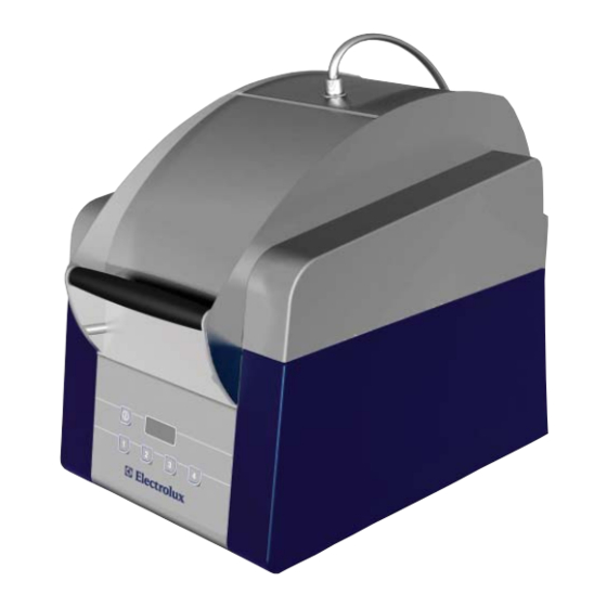
- Page 8 1-2 EXPLANATION OF THE APPLIANCE: The appliance is a product specifi cally designed for Hot Sandwich Outlets, with the following main characteristics: • Great tasting, hot, toasted Sandwich in about less than 60” (depending on the sandwich), in a one-step-solution; •...
- Page 9 Microwave leakage Go to this test only if the above described “General integrity and b) Check the mechanical condition of the appliance cleanliness” test was passed! Glass: Prepare and switch on your Microwave Detector (see “List of - Cracks of the glass. required instruments for maintenance &...
-
Page 10: Error Codes
Error codes ERROR CODES DESIGNATION Err 1 Bottom probe Err 2 Top probe Err 3 Overheating HV transformer Err 4 Front magnetron circuit problem Err 5 Rear magnetron circuit problem Err 6 Both magnetrons circuit problem How to enter the Program mode Unplug the machine. - Page 11 Explanation on software settings EU Version (U207) 7/38...
- Page 12 Explanation on software settings US Version (U202-U208) 8/38...
- Page 13 Settings Table For US Version U202 Since 09061 - Until 09122 Parameters Range Default New Parameters 10s - 60s Duty 1s - 30s 0s - 30 s 5 min - 60 min Stby 1 min - 10 min 10s - 3 min 150°C - 250 °C / 300°F - 482°F 240°C / 464°F Temp 150°C - 280°C / 300°F - 536°F...
- Page 14 Settings Table For EU Version U206 Since 09131 - Until 09191 Parameters Range Default New Parameters 10s - 60s Duty 1s - 30s 0s - 30 s 5 min - 60 min Stby 1 min - 10 min 10s - 3 min 150°C - 250 °C / 300°F - 482°F Temp 150°C - 280°C / 300°F - 536°F...
- Page 15 Parameters details Parameters details HSG Panini HSG Panini DUTY Total time of a period in the duty cycle (in seconds). Time where the resistance of the bottom plate is switched on during the period T1 (in seconds). T˚ bottom ≈ 250˚C / 482 F T2 = 12 with T1 = 30 T˚...
- Page 16 Std By Time before Std By (in minutes) Total time of a Std By period (in minutes) Time where the bottom plate resistance is switched on during T5 (in minutes). Std By cycle chronogram : Standard cooking Time before Stby cycle cooking cycle Temp...
- Page 17 1/2/3/4 Total time of the cycle in seconds Microwaves time during the cycle total time Tcy cycle chronogram : on resistance + mw off mw off resistance 13/38...
- Page 18 Problem Check if … If not, action to do The unit doesn’t power up Yes: Check ... no LED light on beside the ON/OFF switch button plug is inside the socket plug in circuit breaker is on re-engage voltage arrives to the outlet problem not related to the unit voltage arrives to the terminal block replace the cable and cord...
- Page 19 Problem Check if … If not, action to do the top heating element is absor- replace the upper plate kit bing current with the Multimeter (approx. 4amps) cabling between terminal block connect the wires and the board (connector 5) is connected the board is not giving power to the replace the board...
- Page 20 Problem Check if … If not, action to do there is an airfl ow from the exhaust reconnect the exhaust pipes to the pipes in the rear of the machine exhaust pipes support or remove possible clogging obstacles inside the pipes the fan cabling is connected reconnect the wires of the fan there is power supply on both...
- Page 21 Problem Check if … If not, action to do magnetic detectors are working by readjust or change the magnetic a continuity test from the connectors detectors 14/15 (by closing the lid) KS2 is working by visually checking reconnect the wires or replace the the light on when starting a cycle static relay switch breaker of the primary...
- Page 22 Problem Check if … If not, action to do the resistor wiring 51 and 52 is reconnect or replace if damaged connected and not damaged (re- sistor to terminal block and terminal block to board) The value of the resistance of the replace the probe probe is approximately 1,1KOhm at room temperature (1,074 Kohm at...
- Page 23 Problem Check if … If not, action to do Upper plate releasable, but not there are obstacles for a free deblock the upper plate by removable completely from the movement cleaning and/or repairing cooking chamber the upper plate cable is free to deblock it or help manually to enter into the cooking chamber enter...
- Page 24 Problem Check if … If not, action to do louvers are not clogged or clean or change the part if deformed necessary Abnormal noise Yes: Check ... Noise during opening/closing lid springs don’t make noise in put some grease or cooking oil the lid movement Noise permanent when ma-...
- Page 25 4-1 COOKING RESULT TROUBLE SHOOTING QUALITY COOKING OF THE SANDWICH If the sandwich is not enough or to much cooked try another program. If there is no adequate program follow the trouble shooting here above: FINDINGS WHAT TO DO The core temperature of the sandwich is - Increase the time of microwave (tw) too cold - If the time of microwave tw is more than the...
- Page 26 5-2 REPLACE THE TOTAL UPPER PLATE KIT Remove the complet upper plate kit including upper plate cable Switch off and disconnect the machine. ( item S21 on the cover exploded view ). Open the back panel of the tilting box ( items 100 and 101 on Assemble the new upper plate kit : articulation exploded view ).
- Page 27 5-6 REPAIR OR REPLACE THE CHOKE COVER. - The concerned parts must not be touched and the appliance Switch off and disconnect the machine. must not be used for at least 8hours. If the choke cover is damaged, it must be replaced. Therefore: If one or more choke cover pins are missing: - take out all choke cover pins by using a screw driver.
- Page 28 ADJUST THE SPRINGS : HSPP tech GB 03 09 24/38...
- Page 29 HSPP tech GB 03 09 25/38...
- Page 30 26/38...
- Page 31 5.9 CHANGE THE GAS SPRING 27/38...
- Page 32 28/38...
- Page 33 29/38...
- Page 34 5-10 ADJUST THE MICROSWICTH S3 : Adjustment of the micro switch S3 Composition of the kit 0D7003 1 micro switch support 4 washers M4 2 screws M4 List of tools necessary to repair Screwdriver with Torx T20 socket Ratchet handle with M 7 socket Screwdriver for M3 Wrench 7mm or socket 7mm Multi meter with a BIP function for continuity and 2 holders...
- Page 35 Procedure: (Time of repairing 30 mn) 1 Remove the rear cover (Screwdriver with Torx T20 socket) 2 Move the machine on the right side 3 Disconnect the micro switch 4 Remove the Micro switch support (Ratchet handle with M 7 socket) 31/38...
- Page 36 5 Remove the micro switch and mount it on the new support . This operation is mandatory (Screwdriver for M3 and Wrench 7mm or socket 7mm) 6 Mount 2 washers M4 on the welded screws of the tilting box 7 Mount the micro switch support The wheel must touch the aluminium axis Mount 2 washers M4 Mount the 2 nuts delivered in the kit...
- Page 37 8 Move the machine upward and put an adhesive tape in order to maintain a gap of 16cm (6.1/4 inch) between the front of the cover and the top cooking surface 9 connect the multi meter on the micro switch and select the BIP continuity function 10 Adjust the micro by pushing it slowly in direction of the aluminium axis until...
- Page 38 11 Remove the adhesive tape and check with the multi meter that the Micro switch OFF ( no beep ) when the cover Is between the close position and a gap of at least12cm (4.3/4 inch) up to 17cm(6.3/4inch) 34/38...
- Page 39 12 Check visually the position of the micro switch wheel to be sure that the wheel is all time align with the cam on the aluminium tube. Check this with cover in open position, in close position. Cover closed Cover open 13 connect the multi meter on the micro switch and select the BIP continuity function.
- Page 40 15 connect the micro switch 16 Remount the rear cover. 17 Test the unit 4 cycles minimum ( warning : made the test only with load ) Follow the standard procedure of check list after each intervention : 36/38...
- Page 41 37/38...
- Page 42 5-11 WIRES POSITION : To don’t have disturbance in the cabling, respect the position of the wires like on the following picture. 38/38...
- Page 44 Nomenclature S/E cavitée / Cavity sub assy Parts list / Stückliste Baugruppe Kavität R ep. Code Item Part N° Désignation Description Bezeichnung P os. Teile-Nr 1 0D6773 Vitre + joint Glass panel + sea Scheibe + Dichtung 2 Voir S1 Support de vitre Glass support Scheibenhalterung 3 0D6775 Sonde inférieur Lower sensor Untere Sonde 4 0D6776 Aiguille ressort jeu x2 Needle spring set x2 Nadelfeder (2-er Satz)
- Page 45 Vue éclatée S/E cavitée / Cavity sub assy exploded view / Explosionszeichnung Baugruppe Kavität / Esploso Sottinsieme cavità / Despiece S/C cavidad / Sprängskiss Monteringsgrupp för håligheten HSPP FR 03 09...
- Page 46 Sperrklotz 33 Voir S13 Bandeau avant Front strip Vorderes Blech 34 0D6795 Vis H M4x6 inox jeu x10 Screw H M4x6 stainless steel set x10 Sechskantschraube M4x6 Edelstahl (10-er Satz) 0D0631 Rondelle contact de 4 jeu x10 Contact washer size 4 set x10 4-er Kontaktscheibe (10-er Satz) 35 0D6881 Tableau de bord pan usa Pan USA control panel Bedienerfeld PAN USA 0D6882 Tableau de bord electrolux Electrolux control panel Bedienerfeld Electrolux 36 0D7014 Déflecteur Deflector Abweiser S10 0D6790 Tôle de fond + vis Base plate + screws Bodenplatte + Schrauben S11 0D6792 Plaque frontale + vis Front plate + screws Vorderplatte + Schrauben S12 0D6793 Plot de verrouillage équipé...
- Page 47 Vue éclatée Carrosserie / Casing exploded view / Explosionszeichnung Gehäuse / Esploso carrozzeria / Despiece carrocería / Sprängskiss överrede HSPP FR 06 09...
- Page 48 Nomenclature Couvercle / Cover Parts list / Stückliste Abdeckung R ep. Code Item Part N° Désignation Description Bezeichnung P os. Teile-Nr 40 0D6980 Cable Cable Kabel 41 0D3343 Bouton M4-8252 jeu x2 Button M4-8252 set x2 Taste M4-8252 (2-er Satz) 42 0D6797 Trappe arrière Rear hatch Hintere Klappe 43 0D6786 Vis H embase cranté M6x12 jeu x10 Screw H notched base M6x12 set x10 Sechskant-Bundschraube mit Verzahnung M6x12 (10-er Satz) 44 0D0583 Ecrou borgne M6 jeu x10 Cap nut M6 set x10...
- Page 49 Vue éclatée Couvercle / Cover exploded view / Explosionszeichnung Haube HSPP FR 03 09...
- Page 50 Nomenclatura coperchio / Nomenclatura tapa / Specifikation lock N°. N Código Designazione Descripción Beskrivning R ef. 40 0D6980 Tubo spirale Tubo espiral Spiralrör 41 0D3343 Pulsante M4-8252 set x2 Botón M4-8252 juego x 2 Knapp M4-8252 mutterdragarsats x2 42 0D6797 Serranda posteriore Trampilla trasera Bakre lucka 43 0D6786 Vite H zoccolo intagliato M6x12 set x10 Tornillo H base dentada M6x12 juegox10 Skruv H med hake M6x12 mutterdragarsats x10 44 0D0583 Dado esagonale M6 set x10 Tuerca ciega M6 juego x10 Rundmutter M6 mutterdragarsats x10 45 Voir S20 Serranda anteriore Trampilla delantera...
- Page 51 Esploso coperchio / Despiece tapa / Sprängskiss lock HSPP FR 03 09...
- Page 52 Nomenclature Articulation / Hinge Parts list / Stückliste Gelenk R ep. Code Item Part N° Désignation Description Bezeichnung P os. Teile-Nr 80 0D6971 Microrupteur sécurité Safety microswitch Mikroschalter Sicherheit 81 0U0268 Plaquette isolante Insulating plate Isolierblech 82 0D6814 Support microrupteur Microswitch support Halterung Mikroschalter 83 0KL159 Ecrou HU M4 jeu x10 Nut HU M4 set x10 Mutter HU M4 (10-er Satz) 84 0KQ511 Vis C 3x16 inox jeu x10 Screw C 3X16 stainless steel set x10 Schraube C 3x16 Edelstahl (10-er Satz)
- Page 53 Vue éclatée Articulation / Hinge exploded view / Explosionszeichnung Gelenk HSPP FR 06 09...
- Page 54 Nomenclatura articolazione / Nomenclatura articulación / Specifikation Rotation N°. N Código Designazione Descripción Beskrivning R ef. 80 0D6971 Microruttore sicurezza Microinterruptor de seguridad Mikrosäkerhetsbrytare 81 0U0268 Placca isolante Placa aislante Isoleringsplatta 82 0D6814 Supporto microruttore Soporte microinterruptor Stöd till mikrosäkerhetsbrytare 83 0KL159 Dado HU M4 set x10 Tuerca HU M4 juego x 10 Mutter HU M4 mutterdragarsats x10 84 0KQ511 Vite C 3x16 inox set x10 Tornillo C 3x16 inox juego x 10 Skruv C 3x16 i rostfritt stål mutterdragarsats x10 033986 Rondella M3 set x10 Arandela M3 juego x 10...
- Page 55 Esploso articolazione / Despiece articulación / Sprängskiss Rotation HSPP FR 06 09...
- Page 56 Nomenclature Magnétron / Magnetron Parts list / Stückliste Magnetron R ep. Code Item Part N° Désignation Description Bezeichnung P os. Teile-Nr 110 0D6829 Gaine évacuation arrière Rear discharge duct Schlauch hinterer Auslass 111 0D6830 Vis H embase crantée M5x12 jeu x10 Screw H notched base M5x12 set x10 Sechskant-Bundschraube mit Verzahnung M5x12 (10-er Satz) 112 0D5992 Vis tôle Cx 4,2x9,5 Zn jeu x10 Metal screw CX 4.2x9.5 galva set x10 Blechschraube CX 4,2x9,5 Zn (10-er Satz) 113 0D6831 Magnétron Magnetron Magnetron 114 0D6832 Liaison magnétron / ventilateur Magnetron/fan connection...
- Page 57 Vue éclatée Magnétron / Magnetron exploded view / Explosionszeichnung Magnetron / Esploso Magnetron / Despiece Magnetrón / Sprängskiss Magnetron HSPP FR 03 09...
- Page 58 Nomenclature Electrique / Electric Parts list / Stückliste Elektrik R ep. Code Item Part N° Désignation Description Bezeichnung P os. Teile-Nr 130 0D6851 Ventouse magnétique Electromagnet Elektromagnet 131 0D6845 Support ventouse Support electromagnet Halterung Elektromagnet 132 0D6783 Ecrou HU M5 embase crantée jeu x10 Nut HU M5 notched base set x10 Sechskant-Bundmutter mit Verzahnung M5 (10-er Satz) 133 0D6844 Joint v-ring V40A jeu x5 V-ring seal V40A set x5 Dichtung V-Ring V40A (5-er Satz) 134 0D6846 Détecteur de proximité...
- Page 59 Vue éclatée Electrique / Electric exploded view / Explosionszeichnung Elektrik HSPP FR 03 09...
- Page 60 Nomenclatura elettronica / Nomenclatura electricidad / Specifikation elektronik N°. N Código Designazione Descripción Beskrivning R ef. 130 0D6851 Ventosa magnetica Ventosa magnética Magnetisk hållare 131 0D6845 Supporto ventosa Soporte ventosa Stöd till magnetisk hållare 132 0D6783 Dado HU M5 zoccolo intagliato set x10 Tuerca HU M5 con base dentada juego x10 Mutter HU M5 med gängad botten mutterdragarsats x10 133 0D6844 Guarnizione v-ring V40A set x5 Junta v-ring V40A juego x 5 Sluten v-ring V40A mutterdragarsats x5 134 0D6846 Sensore di prossimità Detector de proximidad Närhetsdetektor 135 0D5308 Vite C M3x12 inox set x10...
- Page 61 Esploso elettronica / Despiece electricidad / Sprängskiss elektronik HSPP FR 03 09...
- Page 62 Schéma électrique - Monophasé 208V 60Hz Electrical wiring diagram - single phase 208V 60Hz HSPP FR 03 09...
- Page 63 Schéma électrique - Triphasé 400V 50Hz Electrical wiring diagram - Three phase 400V 50Hz HSPP FR 03 09...