Raymarine E Series User Reference Handbook
Widescreen multifunction display
Hide thumbs
Also See for E Series:
- Reference manual (360 pages) ,
- Installation instructions manual (112 pages) ,
- Installation manual (54 pages)
Table of Contents
Advertisement
Advertisement
Table of Contents

Related Manuals for Raymarine E Series


Summary of Contents for Raymarine E Series
- Page 3 , SeaTalk and Sportpilot are registered trademarks of Raymarine UK Limited. RayTalk, Seahawk, Smartpilot, Pathfinder and Raymarine are registered trademarks of Raymarine Holdings Limited. FLIR is a registered trademark of FLIR Systems, Inc. and/or its subsidiaries. All other trademarks, trade names, or company names referenced herein are used for identification only and are the property of their respective owners.
-
Page 5: Table Of Contents
Contents Chapter 1 Important information....... 9 3.5 Hybridtouch overview ..........25 3.6 Touchscreen overview ..........26 Safety notices..............9 3.7 Home screen overview ..........26 TFT LCD Displays ............10 3.8 Pages ..............27 Water ingress ..............10 3.9 Applications .............. 29 Disclaimers .............. - Page 6 5.2 Routes ..............60 7.7 Autopilot alarms ............108 5.3 Tracks ..............66 Chapter 8 Using alarms and MOB 5.4 Waypoints, routes and tracks storage capacity .... 68 functions ..............109 8.1 Using Man Overboard (MOB) functions ....110 Chapter 6 Using the chart........69 8.2 Alarms..............111 6.1 Chart application overview .........
- Page 7 10.3 Classes of AIS data..........152 12.7 Fishfinder waypoints..........183 10.4 Enabling AIS............153 12.8 Fishfinder alarms........... 183 10.5 Displaying AIS vectors........... 153 12.9 Fishfinder setup ............ 184 10.6 AIS status symbols..........154 Chapter 13 Using the engine application ..... 191 10.7 AIS silent mode.............
- Page 8 22.5 Cleaning the display screen ........256 Chapter 18 Using video.......... 225 Chapter 23 Technical support ....... 257 18.1 Video application overview........226 23.1 Raymarine customer support ......... 258 18.2 Using video............227 23.2 3rd party support ........... 259 Chapter 19 Using the thermal camera application...............
-
Page 9: Chapter 1 Important Information
It is the user’s responsibility to use official government charts, notices to mariners, caution and proper navigational Warning: Sonar operation skill when operating this or any other Raymarine product. • NEVER operate the sounder with the boat out of the water. -
Page 10: Tft Lcd Displays
• Do NOT use a jet wash. when operating this or any other Raymarine product. This product supports electronic charts provided by third party data suppliers which may be embedded or stored on memory card. Use of such... -
Page 11: Chart Cards And Memory Cards
CompactFlash card slot on your unit. The microSD or microSDHC chart card must be inserted into the adaptor. Raymarine does not warrant that this product is error-free or that it is compatible with products manufactured by any person or entity Use branded chart cards and memory cards other than Raymarine. -
Page 12: Connections To Other Equipment
Directive requires the recycling of waste electrical and electronic equipment. Whilst the WEEE Directive does not apply to some Raymarine products, we support its policy and ask you to be aware of how to dispose of this product. Warranty registration... -
Page 13: Chapter 2 Handbook Information
Chapter 2: Handbook information Chapter contents • 2.1 Handbook information on page 14 • 2.2 Handbook conventions on page 15 Handbook information... -
Page 14: Handbook Information
E-Series handbooks The E-Series Widescreen Multifunction Display has the following handbooks available: All documents are available to download as PDFs from www.raymarine.com E-Series Widescreen User reference... -
Page 15: Handbook Conventions
2.2 Handbook conventions Conventions used in this handbook. The following conventions are used throughout this handbook when referring to: • Softkeys — the term "select" is used in procedures involving softkeys to refer to the action of selecting a softkey, either using touch or by pressing the corresponding physical key. - Page 16 E-Series Widescreen User reference...
-
Page 17: Chapter 3 Getting Started
Chapter 3: Getting started Chapter contents • 3.1 Multifunction display system integration on page 18 • 3.2 Networking constraints on page 21 • 3.3 Display power on page 22 • 3.4 Controls on page 23 • 3.5 Hybridtouch overview on page 25 •... -
Page 18: Multifunction Display System Integration
3.1 Multifunction display system Your multifunction display uses a number of protocols to transfer data between the various devices in your networked system. The integration following table details which devices may be connected to your display, and the type of connectivity (in terms of protocols and You can connect a number of external devices to your multifunction physical interfaces): display, providing additional features and functions. - Page 19 Device Type Suitable Devices Connectivity Device Type Suitable Devices Connectivity of ONE of the following Radar Up to two Raymarine SeaTalk Raymarine fishfinders: radar scanners may be connected to your • DSM 30 multifunction display, but only one may be •...
- Page 20 ONE of the following of ONE of the following AIS units: Raymarine thermal cameras: • Raymarine AIS 250 • T300 thermal camera • Raymarine AIS 500 (9 Hz) • Third-party AIS Class • T303 thermal camera A or Class B receiver...
-
Page 21: Networking Constraints
3.2 Networking constraints – E-Series Widescreen units do NOT share home screens with GPM processor units. The following constraints apply when networking an E-Series Widescreen display with a G-Series system. Cartography sharing • Chart card cartography is shared between E-Series Widescreen General displays and G-Series GPM processor units. -
Page 22: Display Power
Powering the display on Widescreen display it must be connected directly to the E-Series Widescreen display using SeaTalk . It must NOT be connected 1. Press and hold the POWER button until the Raymarine logo to the G-Series SeaTalk bus. appears. -
Page 23: Controls
3.4 Controls Screen item Description Chart card slot — open the card reader door to insert or remove CompactFlash (CF) cards. CF cards are used for additional cartography, archiving waypoint, route, and track data, and upgrading system software. Home — displays the home screen, where you can access all the application pages and your waypoint, track, and route data. - Page 24 UniControl Touch icons The UniControl provides a number of key functions in a single You can use the BACK and CLOSE icons to move between the control. different levels of softkeys available in each application. Back — go back one level (same effect as CANCEL button).
-
Page 25: Hybridtouch Overview
Course Over Ground Chart may also be situations (such as rough sea conditions) when it is not vector appropriate to use the touchscreen. In these situations, Raymarine Radar Center of radar strongly recommends that you enable the touch lock, and use the physical keys to operate your multifunction display. -
Page 26: Touchscreen Overview
• Placing and moving the cursor. • Placing and moving VRMs and EBLs. Note: Raymarine strongly recommends that you familiarize yourself with touch operations while your vessel is anchored or moored. You may find it helpful to use the simulator mode (accessible from Menu >... -
Page 27: Pages
3.8 Pages Screen item Description Touch Lock — select this icon to lock the touchscreen, Pages are used on your multifunction display to show applications. preventing accidental use. To unlock, use the UniControl Pages are displayed and accessed on the home screen. Each page to deselect the Touch Lock icon. - Page 28 Multiple applications 1. Use the MORE softkey to scroll to a home screen that has space for new page icons. With most applications, it is possible to run 4 instances of the same 2. Select the Customize icon. application at any one time. However there are 2 exceptions to this, which are: A number of empty page icons appear.
-
Page 29: Applications
3.9 Applications Data application — view system and instrument data on your multifunction display, for a range of compatible Chart application — provides a 2D instruments. or 3D graphical view of your charts to help you navigate. Waypoint, route, and track functions enable you to navigate to a specific location, build and navigate routes, or record where you’ve been. -
Page 30: Screen Overview
3.10 Screen overview Weather application — (North America only). With a suitable weather receiver connected to your system, the weather application overlays historical, live, and forecasted weather graphics on a world map. Video application — view a video or camera source on your multifunction display. - Page 31 Screen item Description Screen item Description Edit dialogs — enable data to be edited or entered into a Back — select this icon to go back to a previous menu. list — for example, editing a waypoint.. Menu item — momentarily touching a menu item highlights Pop-up messages —...
- Page 32 Using edit dialogs Edit dialogs enable you to edit the details of data items stored on your multifunction display, such as waypoints, routes, and tracks. The following diagram shows the main features of a typical edit dialog: Screen item Description Back —...
- Page 33 Screen item Description Back — select this icon to go back to a previous dialog. Field — touching a text field automatically displays the on-screen keyboard, which can be used to edit the details. For numeric fields, the on-screen keyboard is displayed when you select the field and the EDIT USING KEYPAD softkey.
-
Page 34: Editing Information In Dialogs
3.11 Editing information in dialogs 3.12 Basic touchscreen operations With the dialog displayed: Placing and moving the cursor using touch 1. Select the field you want to edit. 1. Touch the screen at any position on the screen to place the The on-screen keyboard is displayed: cursor there. -
Page 35: Databar Status Symbols
3.13 Databar status symbols 1. Select the Touch Lock icon. It changes color to indicate that the touchscreen is disabled. All The status symbols on the databar confirm whether the appropriate functions are still available using the buttons and softkeys. connections to your system have been made. - Page 36 Radar Symbol Description power AIS unit is in Silent Mode. Symbol mode Description Scanner powered off when radar not required, but display is in use for other applications, such as the chart. When AIS unit is in Silent Mode, with active alarms. selected, the system counts down.
- Page 37 GPS status symbols Symbol Description The GPS receiver status is indicated in the databar. Autopilot alarm active. Symbol Description A GPS receiver is connected and has Dodge mode is active. obtained a fix. A GPS receiver is not connected, or cannot obtain a fix.
-
Page 38: Initial Setup Procedures
Symbol Description Once your display has been installed and commissioned (see The touchscreen is unlocked. Installation Guide), Raymarine recommends that you: • Set the language, the date and time format and preferred units of measurement. • Set your vessel details. - Page 39 Touchscreen alignment 2. Select System Setup. 3. Select Boat Details. If the touchscreen is misaligned to your touch, you can realign it 4. Change the Safe Depth, Safe Height and Safe Width settings to improve the accuracy. as appropriate for your vessel. Realignment involves a simple exercise to align an on-screen object with your touch.
- Page 40 • Data received from the autopilot, instruments, the engine and other external sources. Note: Raymarine recommends that you do NOT use the simulator mode whilst navigating. Your system may be wired for redundancy with data connections made to repeat displays.
- Page 41 Enabling the simulator mode 1. Press Menu. 2. Select the System Setup menu. 3. Select the Simulator item, and change its value to On. Adjusting the simulator vessel speed 1. Press the MENU button. 2. Select System Setup. 3. Select Simulator Speed. 4.
- Page 42 E-Series Widescreen User reference...
-
Page 43: Chapter 4 Managing Display Data
Chapter 4: Managing display data Chapter contents • 4.1 Memory cards overview on page 44 • 4.2 Inserting a memory card, chart card, or CF / microSD card adaptor on page 44 • 4.3 Ensure chart card door is securely closed on page 45 •... -
Page 44: Memory Cards Overview
It should position easily. If it does not, DO NOT force it, check the direction in which the lip is facing. Note: Raymarine recommends that you backup your data to a memory card on a regular basis. 4. Gently press the card or adaptor all the way in to the card slot. -
Page 45: Ensure Chart Card Door Is Securely Closed
4.3 Ensure chart card door is securely 4.4 Removing a memory card, chart closed card, or CF / microSD adaptor 1. If the system is powered on, press the MENU button. Otherwise, Prevent water ingress. skip to Step 3. To prevent water ingress and consequent damage to the display, 2. -
Page 46: Saving User Data And User Settings
NOT to a chart card containing cartography. Note: Raymarine recommends that you save your user data and user settings to a memory card on a regular basis. 1. Insert card in to the card slot. -
Page 47: Transferring Data Using Nmea
4.6 Transferring data using NMEA 6. To save all items of that type of data, select the SAVE ALL... softkey. You can transfer waypoints or routes to and from your multifunction 7. To save an individual item of data, select the item from the list display and an external instrument, using NMEA. -
Page 48: Resetting Your System
4.7 Resetting your system 1. Press the MENU button. 2. Select System Setup. Your system may be reset to its factory default settings if required. 3. Select Settings and Data Reset. There are 2 types of reset operation, both of which affect the current 4. -
Page 49: Chapter 5 Using Waypoints, Routes And Tracks
Chapter 5: Using waypoints, routes and tracks Chapter contents • 5.1 Waypoints on page 50 • 5.2 Routes on page 60 • 5.3 Tracks on page 66 • 5.4 Waypoints, routes and tracks storage capacity on page 68 Using waypoints, routes and tracks... -
Page 50: Waypoints
5.1 Waypoints By default, all waypoints are indicated on screen by a waypoint symbol (x). You can assign different symbols if required. A waypoint is a position marked on the screen to indicate a site or a place to navigate to. Waypoints in the radar application As well as acting as position markers, waypoints are also the In the chart and radar applications both active and inactive... - Page 51 • Erase waypoint. • Move waypoint. • Go to waypoint. • View / edit waypoint. Waypoint features There are a range of features for placing, navigating and managing waypoints. Waypoint features are accessed from: • the chart or radar application — by positioning the cursor over Waypoints in the fishfinder application an existing waypoint on the screen.
- Page 52 Placing a waypoint at the cursor position Waypoint function All applications Home screen In the chart, radar, fishfinder, or CDI application: Move waypoints 1. Press the WPTS MOB button. 2. Move the cursor to the area of the screen where you want the Creating and managing waypoint waypoint to be placed.
- Page 53 Waypoint navigation 1. Place the cursor over the waypoint. The softkeys change to show the waypoint options. Navigating to the cursor position on the chart 2. Select the GOTO WAYPOINT softkey. The required course heading to the waypoint is shown on the screen.
- Page 54 • Name Editing a waypoint on the chart or radar screen In the chart or radar application: • Position (as Lat/Lon and range/bearing from vessel) 1. Place the cursor over the waypoint. • Temperature (requires appropriate sensor, only for waypoints The softkeys change to show the waypoint options.
- Page 55 Symbol Type Symbol Type Symbol Type Symbol Type End marker Small fish Sport fisher Fish Fish (1–star) Square Start marker Fish (2–star) Fish (3–star) Swimming Tank Fish trap Hill peak Top mark Tower Ledge Lobster Trawler Tree Lost target Man overboard (MOB) Triangle Wreck Marker...
- Page 56 Showing and hiding waypoint groups / symbols Moving a waypoint by entering new coordinates In the chart, radar, fishfinder, or CDI application: With the Waypoint List displayed: 1. Press the WPTS/MOB button. 1. Select the VIEW AND EDIT DETAILS softkey. 2.
- Page 57 6. Select the YES softkey to confirm, or the NO softkey to cancel. 4. Select the on-screen keyboard’s SAVE key. Note: If a route is hidden, its waypoints can still be displayed. If Moving waypoints between groups you attempt to erase a waypoint from a hidden route, a warning is With the Waypoint Group List displayed: displayed, and the waypoint cannot be erased.
- Page 58 Erasing a waypoint group 2. Press the DATA button. 3. Select the ARCHIVE AND TRANSFER softkey. When you delete a waypoint group, the group name and all the associated waypoints are erased from the system. If a group 4. Select the SAVE TO CARD softkey. contains one or more waypoints that you want to keep, move these 5.
- Page 59 Password Protection is set to ON or OFF. 11. Press the OK button. Note: Raymarine strongly recommends that you backup your The password is now set and protection enabled, although access waypoint data BEFORE password protecting your waypoints.
-
Page 60: Routes
5.2 Routes 5. Enter your new waypoints password (1 to 16 characters, and case sensitive). A route is a series of waypoints typically used to assist with passage 6. Press the OK button. planning and navigation. 7. Repeat Steps 5 to 6 to confirm the password. A route is displayed on screen as a series of waypoints linked by a 8. - Page 61 • Build and save a route for use when required (stored in the route Building a route using touch list). • Navigate (follow) routes. • Manage and edit routes stored on the system. You can also build a route from an existing track. Select the My Tracks icon to access track functions on the home screen.
- Page 62 • To use an existing waypoint select the USE THIS WAYPOINT softkey. • For a new waypoint select the PLACE WAYPOINT softkey. 5. Repeat Steps 3 to 4 for each subsequent waypoint, until the route is complete. 6. To follow the route immediately without saving it for future use (Quick Route), select the FOLLOW (QUICK) ROUTE softkey.
- Page 63 2. Select the CREATE ROUTE FROM TRACK softkey. 2. After adding the final waypoint in your route, press the FOLLOW (QUICK) ROUTE softkey. 3. Select the YES softkey to name the route, or NO to accept the default route name. Note: You can stop following a route at any time by pressing A route will be created and the current track will continue to be the STOP FOLLOW softkey.
- Page 64 Advancing to the next waypoint in a route You can skip the current active waypoint and advance to the next waypoint in a route at any time. While following a route in the chart application: 1. Press the GOTO softkey, or position the cursor over the route. 2.
- Page 65 Review or edit a route 1. Select the PLANNING softkey. 2. Select the MY ROUTES softkey. There are a variety of attributes associated with routes. These can be reviewed and edited. 3. Select the route you want to add a waypoint to. You can: 4.
-
Page 66: Tracks
5.3 Tracks 3. Move the cursor so that it stretches the leg of the route to the desired position on the chart. A track is an on-screen trail that shows the route you have taken. 4. Select the PLACE WAYPOINT softkey. This trail is made up of a series of track points which are created automatically. - Page 67 • With the chart application active, use the following softkey Note: If the maximum number of tracking points is reached, you sequence, Navigation options > Planning > My Tracks. will be warned. The track will continue to be recorded with the earlier tracking points being overwritten.
-
Page 68: Waypoints, Routes And Tracks Storage Capacity
5.4 Waypoints, routes and tracks storage • Units of time from the list displayed (available if “record track interval by” is set to time). capacity • Units of distance from the list displayed (available if “record track interval by” is set to distance). The display can store the following quantities of waypoints, routes and tracks •... -
Page 69: Chapter 6 Using The Chart
Chapter 6: Using the chart Chapter contents • 6.1 Chart application overview on page 70 • 6.2 Vessel position and orientation on page 72 • 6.3 Chart views on page 75 • 6.4 Chart planning options on page 79 • 6.5 Chart navigation options on page 79 •... -
Page 70: Chart Application Overview
6.1 Chart application overview The chart application provides an electronic chart with passage planning and navigation features. It combines 2D and 3D viewpoints and provides a variety of cartographic information regarding your surroundings and charted objects. Typical uses for the chart application include : •... - Page 71 To avoid irreparable damage to and/or loss of data datum on the multifunction display. from chart cards: • If you have a Raymarine GPS receiver using NMEA0183, or a • Ensure that chart cards are fitted the correct way third-party GPS receiver, you must correlate it separately.
-
Page 72: Vessel Position And Orientation
Your current position is represented on screen by a boat symbol. • Hotmaps The boat symbol is shown below: Note: Refer to the Raymarine website (www.raymarine.com) for the latest list of supported chart cards. Note: The boat symbol can be customized, so may appear differently on your display. - Page 73 North Up (N-up) Note: It is not possible to select Head Up when the motion mode is set to True. Course Up (C-up) In North Up mode, the chart orientation is fixed with true north upwards. As your heading changes the vessel symbol moves accordingly.
- Page 74 2. Select Chart Setup. When the motion mode is set to Relative, the position of your vessel is fixed on the screen and the chart picture moves relative to your 3. Use the Chart Orientation menu item to select the Head-Up, vessel.
-
Page 75: Chart Views
6.3 Chart views Setting the motion mode In the chart application: The chart is viewed and manipulated in 3 dimensions. It can be 1. Press the MENU button. viewed from directly overhead (2D view) or at an angle (3D view) 2. - Page 76 2D chart view Item Description The 2D chart view displays a range of information to help you Motion mode — states the current motion mode (Relative, navigate. True, or Autorange). Cartographic objects — use the Cartography Setup menu to choose which objects to display. AIS target —...
- Page 77 3D chart view Item Description The 3D chart view includes a number of functions to help you Center-of-view — the white cross indicates the center navigate your vessel. of chart view at the water level. Cartographic objects — use the Cartography Setup menu to choose which objects to display.
- Page 78 1. Swipe your finger across the display in the direction you want to pan the chart. Switching between 2D/3D chart view You can quickly toggle between 2D and 3D views. In the chart application: 1. Select the PRESENTATION softkey. 2. Select the 2D or 3D option, using the VIEW softkey. 2.
-
Page 79: Chart Planning Options
6.4 Chart planning options 6.5 Chart navigation options The chart provides features to help plan your navigation to a chosen The chart provides features to help navigate to a chosen location. location. The Navigation Options are found on the chart toolbar softkeys — The options are found on the chart softkeys —... -
Page 80: Measuring Distances And Bearings
6.6 Measuring distances and bearings Clearing the chart ruler In the chart application: You can use the databar information and the ruler to measure 1. Select the NAVIGATION softkey. distances in the chart application. 2. Select the RULER softkey. You can determine the distance and bearing: 3. -
Page 81: Chart Vectors
6.7 Chart vectors Note: If neither Speed Over Ground (SOG) or heading data is available, vectors cannot be displayed. Chart vectors display indicators for heading and COG, and wind and tide direction. Vector length A range of vector graphics can be superimposed on to the chart The length of the HDG and COG vector lines is determined by the display. -
Page 82: Current Information
6.8 Current information • The color of the arrow indicates the flow speed: – Red: increasing current flow speed. Animated current information – Blue: decreasing current flow speed. The electronic charts may allow animation of the current information The animation can be viewed continuously or incrementally for current stations. -
Page 83: Tide Information
6.9 Tide information TODAY’S Set the animation date to the current date. DATE Animated tide information PREV DATE Set the animation date to 24-hours previous to current date. The electronic charts may allow animation of the tide information tide stations. NEXT DATE Set the animation date to 24-hours ahead of Animated current information is available in the chart application... - Page 84 Displaying details of tides Viewing animated tide information In the chart application: In the chart application: 1. Position the cursor over a diamond-shaped tide icon. 1. Position the cursor over the diamond-shaped tide symbol. 2. Press the OK button to display the Object Info dialog box. 2.
-
Page 85: Chart Object Information
6.10 Chart object information 1. Position the cursor over the object. A pop-up is displayed, showing the basic object information. You can display additional information on the chart for cartographic 2. Press the OK button. objects, ports, and marinas. Detailed information for that object is displayed, and the softkeys You can also search for the nearest instance of a particular chart change to provide the FIND NEAREST and SEARCH BY NAME object and search for ports by name. -
Page 86: Chart Layers
6.11 Chart layers 5. Select the SEARCH softkey. The search results are displayed. The chart has a number of content layers and display modes 6. Select an entry in the list to display more information. providing different kinds of display and information. You can overlay data onto a chart window to give greater depth of Displaying pilot book information information. - Page 87 Aerial photo overlay Specifying aerial overlay opacity In the 2D chart view: Your electronic charts may include aerial photography. 1. Select the 2D CHART LAYERS softkey. 2. Use the AERIAL OVERLAY softkey to select the ON option. The opacity bar is displayed above the softkey. 3.
- Page 88 Radar overlay Chart scale and radar range synchronization You can combine the chart with the radar and MARPA functions You can synchronize the radar range in all radar windows with the to provide target tracking or to help you distinguish between fixed chart scale.
- Page 89 NOWRad weather overlay Range rings With a suitable weather receiver connected to your multifunction display, you can overlay NOWRad weather information on the chart display. The NOWRad weather overlay provides NOWRad weather information and reports in the chart application. You can adjust the intensity of the overlay to achieve optimal visibility of both chart and weather information.
-
Page 90: Chart Presentation
6.12 Chart presentation 3. Use the TROPICAL STATEMENTS, MARINE WARNINGS, MARINE ZONE FORECASTS, or WATCHBOX WARNINGS The chart has a number of presentation options which affect the softkeys to select the required weather reports. level of detail, types of objects and aspects of its operation. The presentation options available are: •... - Page 91 Chart Detail 2. Use the SYNC softkey to select the CHRT option. 3. If you have networked displays, repeat Step 2 in the chart application on each display that you want to synchronize. Fish mode Fish mode provides bathymetric contour data on the chart for use during fishing.
- Page 92 2. Use the CHART DETAIL softkey to select the HIGH or LOW option, as appropriate. E-Series Widescreen User reference...
-
Page 93: Chart Setup
6.13 Chart setup The set up for your chart and its cartography can be changed from the standard configuration to suit your particular needs. Although you will probably only do this when you first use the chart, you may decide to make subsequent adjustments once you become more familiar with the system. - Page 94 Chart setup menu options The following table describes the various options in the Chart Setup Menu for your multifunction display. Menu item Description Options Chart Orientation Chart orientation is the relationship between the chart and the direction • Head-Up that you are travelling in. This menu option enables you to choose •...
- Page 95 Menu item Description Options 3D set up Settings specific to the 3D chart view: • Center-of-view indicator: • Center-of-view indicator — determines whether a white cross is – ON displayed, indicating the centre of view. – OFF (default) • Trans Cone — displays a transducer cone below the vessel icon, •...
- Page 96 Menu item Description Options • Vector Width — sets the width of the COG and HDG (heading) – 3 Mins chart vector lines. – 6 Mins • Route Width — sets the width of route lines. – Infinite (default) • Range Rings — displays radar range rings on the chart display. •...
- Page 97 Menu item Description Options Record Vessel Track By Determines how track points are recorded on the chart: • Auto (default) • Time • Auto — track points are automatically created. • Distance • Time — track points are created based on time. •...
- Page 98 GPS to the new mode, and indicates whether this was successful or not. Note: Raymarine recommends that you check the displayed vessel position in the chart application against your actual proximity to a known charted object. A typical GPS has an accuracy of between 5 and 15 m.
- Page 99 Cartography setup menu options The following table describes the various options in the Cartography Setup Menu for your multifunction display. Menu item Description Options Chart Display Determines the level of detail shown on the chart. • Simple • Detailed (default) •...
- Page 100 Menu item Description Options Safety Contour The chart will use this depth as the deep water boundary. Water • OFF areas of depth greater than this will be colored using the appropriate • 7 ft Deep Water Color. • 10 ft •...
- Page 101 Menu item Description Options Caution & Routing Data Determines whether caution and routing data is displayed or not. • OFF • ON (default) • OFF — caution and routing data is NOT displayed. • ON — caution and routing data is displayed. Marine Features When this menu item is set to ON, the following water-based •...
- Page 102 Menu item Description Options Additional Wrecks Determines whether extended information for new wrecks is displayed. • OFF • ON (default) Aerial Photo Overlay Determines the areas of the chart covered by the aerial photo overlay • On Land (default) feature. •...
-
Page 103: Chapter 7 Using Autopilot Control
Chapter 7: Using autopilot control Chapter contents • 7.1 Enabling the autopilot control function on page 104 • 7.2 Disengaging the autopilot in an emergency on page 104 • 7.3 Autopilot control on page 105 • 7.4 Autopilot control options on page 106 •... -
Page 104: Enabling The Autopilot Control Function
7.1 Enabling the autopilot control 7.2 Disengaging the autopilot in an function emergency 1. Press the MENU button. While following a route using the autopilot: 2. Select System Setup. 1. Press and release the POWER button. 3. Select System Integration. 2. -
Page 105: Autopilot Control
7.3 Autopilot control You must use the physical keys to select these softkeys. You can use your multifunction display to control your autopilot. Engaging the autopilot Note: For information on connecting an autopilot to your In the chart application: multifunction display, refer to the documentation that accompanies 1. -
Page 106: Autopilot Control Options
7.4 Autopilot control options 7.5 Autopilot dialog box Your multifunction display enables you to navigate to target The autopilot dialog box provides important information when waypoints using the autopilot control options. navigating using the integrated autopilot controls. When you arrive at a waypoint, the Pilot Control dialog is displayed, The following information is displayed: providing the following options: •... -
Page 107: Autopilot Status Symbols
7.6 Autopilot status symbols Symbol Description Power steering active. The autopilot status is indicated in the databar. Symbol Description Autopilot is in Standby mode. Wind Vane mode is active. Autopilot is in Track mode. Autopilot is in Auto mode. No autopilot detected. Autopilot alarm active. -
Page 108: Autopilot Alarms
7.7 Autopilot alarms The autopilot functions provide alarms to alert you to situations that require action. Your multifunction display shows autopilot alarms, regardless of whether there is active navigation on the system. If pilot integration is enabled, and an alarm is raised by the autopilot, the multifunction display provides an audible alarm sound (providing that the alarm has not already been silenced). -
Page 109: Chapter 8 Using Alarms And Mob Functions
Chapter 8: Using alarms and MOB functions Chapter contents • 8.1 Using Man Overboard (MOB) functions on page 110 • 8.2 Alarms on page 111 Using alarms and MOB functions... -
Page 110: Using Man Overboard (Mob) Functions
8.1 Using Man Overboard (MOB) Note: To obtain a MOB position, your multifunction display must functions have a GPS position fix. Man overboard Cancelling a MOB alarm 1. Press and hold the WPTS/MOB button for four seconds. If you lose a person or object overboard, you can use the Man Overboard (MOB) function to mark the position. -
Page 111: Alarms
8.2 Alarms • MOB position data is displayed in the databar along the top of the screen. Alarms alert you to a situation or hazard requiring your attention. • Any chart settings that you make to the special MOB chart You can set up alarms to alert you to certain conditions, such as application will not be saved. - Page 112 System alarm setup Menu item Description Options Menu item Description Options Alarm Clock When set to ON, an • OFF (default) alarm is triggered at Anchor Alarm When set to ON, • OFF (default) • ON the time you specify for the anchor alarm is the Alarm Clock Time •...
- Page 113 Navigation alarms setup Menu item Description Options Menu item Description Options Collision Alarm When Collision Alarm is • OFF (default) set to ON, an alarm is Arrival Alarm Radius When you arrive at a 0.01 to 9.99 nm (or • ON triggered when charted waypoint, an alarm is equivalent units)
- Page 114 • the range in front of your vessel, which can be adjusted between Menu item Description Options 0.05 and 2 nautical miles. Setup Alarm Zone Enables you to specify • the bearing from your vessel (width of the zone), which can be the zone for the Collision adjusted between 0 and 90.
- Page 115 – Cultural features. 7. Press the OK button to save the changes, or the CANCEL button to revert to the previously saved settings. Note: A dotted or dashed collision alarm zone indicates that there is insufficient cartographic information for the collision alarm Radar alarms setup to function correctly.
- Page 116 Menu Item Description Options Menu Item Description Options Fish Alarm Depth Limits If the Fish Alarm and OFF, ON Deep Depth Alarm Deep Depth Alarm OFF, ON this alarm is set to ON, Switches the deep depth an alarm is triggered alarm on or off.
-
Page 117: Chapter 9 Using Radar
Chapter 9: Using radar Chapter contents • 9.1 Radar overview on page 118 • 9.2 Digital radar scan speed on page 118 • 9.3 Radar scanner status symbols on page 119 • 9.4 Radar range and image quality on page 120 •... -
Page 118: Radar Overview
9.1 Radar overview 9.2 Digital radar scan speed Radar is used to provide information that can help you to track Certain digital radar scanners support multiple scan speeds. targets and measure distances and bearings. Radar scan speed is set up using the Digital Scanner Setup Menu, Radio Detection And Ranging (RADAR) is used at sea to detect the accessible from the Radar Setup menu. -
Page 119: Radar Scanner Status Symbols
9.3 Radar scanner status symbols Powering the radar scanner on and off In the radar application: The radar scanner power mode status is indicated in the databar. 1. Press the POWER button on your multifunction display. Radar 2. Using the relevant softkeys, select the operating mode for the power radar scanner. -
Page 120: Radar Range And Image Quality
9.4 Radar range and image quality Radar image quality A number of factors can affect the quality of a radar image, including Maximum radar range echoes, sea clutter, and other interference. Not all radar echoes are produced by valid targets. Spurious echoes The usable range of the radar is limited by factors such as the may be caused by: height of the scanner, and height of the target. - Page 121 Multiple Echoes Multiple echoes are not very common but can occur if there is a large target with a wide vertical surface at a comparatively short range. The transmitted signal will be reflected back and forth between the target and your own ship, resulting in multiple echoes, displayed beyond the range of the true target echo, but on the same bearing.
- Page 122 Interference When two or more radar-equipped vessels are operating within range of each other mutual radar interference can occur. This usually appears as a spiral of small dots from the display centre This type of interference is most noticeable at long ranges. Rain or Snow Clutter The radar can see echoes from rain or snow.
-
Page 123: Radar Display Overview
9.5 Radar display overview Item Description Ship’s position With your radar scanner connected and the radar in transmit mode, the radar picture provides a map-like representation of the area Motion Mode in which the radar is operating. Radar scanner status Waypoint Range ring spacing Typically, your vessel’s position is at the center of the display, and... - Page 124 mountain several miles inland from the coastline. Although the 4. Select the EDIT NAME softkey. coastline may be much nearer, it may not appear on the radar The on-screen keyboard is displayed. until the vessel is closer to shore. 5. Use the on-screen keyboard to enter a name for the scanner, •...
-
Page 125: Dual Range Radar Operation
9.6 Dual range radar operation Dual range radar compatibility The range covered by the short Dual Range option depends on the The Dual Range radar function enables you to view 2 ranges at the radar scanner you are using, and the software version it is using. same time in separate windows. -
Page 126: Radar Mode And Orientation
9.7 Radar mode and orientation Using Dual Range with SuperHD scanners Dual range radar operation with SuperHD scanners. Radar orientation modes When using the short Dual Range option, a SuperHD scanner operates in HD mode only. When using the long Dual Range option, The radar can operate in a number of orientation modes to suit a SuperHD radar operates in SuperHD mode. - Page 127 North Up (N-UP) Course Up (C-UP) If you select a new course, the picture will reset to display the new Note: If heading data becomes unavailable whilst in this mode, course upwards. a warning message will be shown, the status bar indicates The reference used for Course-Up depends upon the information North-Up in brackets and the radar uses 0°...
- Page 128 2. Press the RADAR MODE AND ORIENTATION softkey. 3. Using the ORIENTATION softkey, select the required orientation mode. Changing the radar vessel offset In the radar application: 1. Press the PRESENTATION softkey. 2. Press the RADAR MODE AND ORIENTATION softkey. 3.
-
Page 129: Radar Tuning: Hd And Superhd Digital Scanners
• Buoy — a special mode that enhances the • Gain — enables you to use a preset in automatic picture in different situations. Raymarine strongly detection of small objects like mooring buoys. It is mode, or to adjust its gain manually between 0 recommends the use of these presets to achieve useful at ranges up to 0.75 nm. - Page 130 Tuning method Related options Description – Antenna Boost: scales the effective antenna size. At zero, the effective antenna size matches its actual size. At 95%, the effective antenna size is doubled. Increasing the effective antenna size separates targets that appear merged at lower settings.
- Page 131 • AUTO — the default mode. The radar tunes itself The radar tuning control enables you to fine-tune the automatically on all range scales. Raymarine radar scanner’s receiver for maximum target returns recommends that you leave the tune function in on the display.
- Page 132 1. Select the GAIN softkey. 6. Press the OK button. 2. Select the BUOY MODE, HARBOR MODE, COASTAL MODE, OFFSHORE MODE, or BIRD MODE softkey, as appropriate. Adjusting SuperHD radar antenna boost 3. Select the same softkey again. In the radar application: The softkeys change to provide more options.
- Page 133 1. Press the ENHANCE ECHOES softkey. 2. Press the INT. REJECTION softkey repeatedly until the ON option is selected. 3. Press the OK button. Enabling radar expansion In the radar application: 1. Press the ENHANCE ECHOES softkey. 2. Press the EXPANSION softkey repeatedly until the ON option is selected.
-
Page 134: Radar Tuning: Non-Hd Digital Radomes
9.9 Radar tuning: non-HD digital radomes You can use the gain presets and other functions to improve the quality of the radar picture. The following settings apply to non-HD digital radomes: Tuning method Related Options Description • AUTO — the preset operates in automatic mode. Gain Enables you to adjust the sensitivity of the radar This is the default. - Page 135 • MAN — allows you to manually adjust the intensity takes account of land clutter so that smaller set to automatic mode by default. Raymarine strongly of the sea gain, from 0 to 100%. targets, like navigation buoys, are not lost.
- Page 136 • AUTO — the default mode. The radar tunes itself The radar tuning control enables you to fine-tune the automatically on all range scales. Raymarine radar scanner’s receiver for maximum target returns recommends that you leave the tune function in on the display.
- Page 137 4. Select the Tune menu item. Note: You can adjust the radar’s sensitivity to sea clutter using the MENU > Radar Setup > Scanner Setup > Sea Clutter 5. Select the MANUAL option, using the TUNE softkey. Curve menu item. 6.
-
Page 138: Using Radar To Measure Distances, Ranges, And Bearings
9.10 Using radar to measure distances, ranges, and bearings When you are using the radar application, you can measure distances, ranges and bearings in a variety of ways. These options are detailed in the table below: Distances Range From Functions Between Points Your Vessel Bearings... - Page 139 Note: The default bearing mode for EBLs is relative to your vessel’s heading. If heading data is available, you can set the Measuring using Electronic Bearing Lines (EBLs) bearing mode to be relative (REL), magnetic/true (M/T). When M/T is selected, the EBL bearings will be expressed as either An Electronic Bearing Line (EBL) is a line drawn from your boat to true or magnetic, dependant on the equipment connected.
- Page 140 Note: The first VRM/EBL will be placed at a location of 1/3 of the current range and 030° relative to your vessel’s head. If this setting is adjusted, the display will retain the adjustments and use them when the VRM/EBL is next enabled. Creating a floating VRM or EBL on the radar display In the radar application:...
- Page 141 2. Select Radar Setup. Note: When creating the first VRM/EBL, it will be placed at a location of 1/3 of the current range and 030° relative to your 3. Use the Range Rings menu option to switch Radar Rings ON vessel’s head.
-
Page 142: Using Radar To Track Targets And Avoid Collisions
MARPA will appropriate. perform. For the best heading data, a Raymarine SMART heading 5. Press the ZONE SHAPE softkey until the SECTOR or CIRCLE sensor or a gyro-stabilized autopilot is required. - Page 143 • the symbol wanders away from the target, locks-on to another target, or changes to a lost symbol target. In these circumstances, target acquisition and tracking may need to be re-initiated and in some cases might be impossible to maintain. Better quality heading data might improve performance in these circumstances.
- Page 144 Relative mode With the display set in Relative mode, no vector extension of your vessel is shown. The CPA line emerges from your own vessel, with the target vector extension being shown as relative, not true. The text next to the target indicates its course and speed. Configuring MARPA and AIS options Vessel vectors (CPA graphics) overview In the radar application:...
- Page 145 MARPA options Parameter Descriptions Options The MARPA options are accessible by pressing the TARGET Time to Safe Zone If a target enters your • 3 min TRACKING > MARPA & AIS OPTIONS softkeys. safe zone within this time • 6 min period, it is considered Parameter Descriptions...
-
Page 146: Radar Setup Menu Options
• Tune Adjust — allows you to fine tune the radar scanner’s receiver for • AUTO maximum returns on the display. Raymarine recommends that this function is • MANUAL set to AUTO. If you set this function to MANUAL and adjust the setting shortly... - Page 147 Function Description Options Color Palette (Digital only) The color palette options enable you to customize the look of the radar display for • Bold different situations, as follows: • Professional 1 • Bold — uses high color gain, predominately red, to show weak targets more •...
- Page 148 E-Series Widescreen User reference...
-
Page 149: Chapter 10 Using Ais
Chapter 10: Using AIS Chapter contents • 10.1 AIS overview on page 150 • 10.2 AIS prerequisites on page 151 • 10.3 Classes of AIS data on page 152 • 10.4 Enabling AIS on page 153 • 10.5 Displaying AIS vectors on page 153 •... -
Page 150: Ais Overview
10.1 AIS overview 1. Heading. 2. Large vessel. The AIS feature enables you to receive information broadcast by other vessels, and to add these vessels as targets in the chart and 3. Direction of turn. radar applications. 4. Small vessel. With an optional AIS unit connected to your system you can: 5. -
Page 151: Ais Prerequisites
• A receive-only AIS unit or a full AIS transceiver (a unit that sends AIS Simulator Mode and receives). Raymarine recommends that you use the simulator function to • A VHF antenna - this is usually supplied with the AIS system. familiarize yourself with the AIS features. When the simulator function is enabled (Menu >... -
Page 152: Classes Of Ais Data
10.3 Classes of AIS data Class A Class B Data (receive) Class B (send) (receive) There are 2 classes of AIS data; each class supports a different Antenna location range of AIS data. AIS data is defined as Class A or Class B. The sending and Draft receiving of Class A and Class B data may not be compulsory for all vessels. -
Page 153: Enabling Ais
10.4 Enabling AIS 10.5 Displaying AIS vectors You must have the correct data available before AIS vectors can Enabling AIS in the chart application be displayed. In the 2D chart view: A target is defined as active when it has the following data displayed 1. -
Page 154: Ais Status Symbols
10.6 AIS status symbols 10.7 AIS silent mode AIS status is indicated by a symbol in the databar. AIS silent mode enables you to disable AIS transmissions AIS silent mode enables you to disable the transmitting functions Symbol Description of your AIS equipment. This is useful when you do not want to AIS unit is switched on and operating. -
Page 155: Viewing Ais Target Information
10.8 Viewing AIS target information Target type Description Symbol Dangerous target Targets within specified You can display information relating to individual AIS targets. distance (CPA) or time When a target is highlighted with the cursor, the softkeys change (TCPA). Dangerous to allow you to select the following options: target alarm sounds if enabled. -
Page 156: Using Ais To Avoid Collisions
10.9 Using AIS to avoid collisions Displaying detailed AIS target information In the chart or radar application: You can use the AIS safe zone and safety message functions to 1. In the chart application, select the AIS OPTIONS softkey (or help you avoid collisions with other vessels and objects. -
Page 157: Ais Options
10.10 AIS options • Place a waypoint on your chart / radar to mark the sending vessel’s position. The AIS options are accessible in the chart application by pressing • Select to GOTO the sending vessel’s position. the AIS OPTIONS > MARPA & AIS OPTIONS softkeys, or the radar application by pressing the TARGET TRACKING >... -
Page 158: Ais Alarms
10.11 AIS alarms Parameter Description Options Own Vessel Safe Zone The safe zone is a ring, • 0.1 nm The AIS functions generate a number of alarms to alert you to centred on your boat, dangerous or lost targets. • 0.2 nm within which a target is In addition to the dangerous target alarm previously described, the considered dangerous... -
Page 159: Buddy Tracking
10.12 Buddy tracking How it works When the AIS Layer is enabled in the chart or radar application, AIS You can configure your display to notify you when an AIS-equipped targets are shown on your display. You can add any AIS target to friend or “buddy”... - Page 160 Adding a vessel to your buddy list from AIS Editing a buddy’s details target list 1. In the chart or radar application, use the trackpad to move the cursor over an AIS target. 1. If you are in the chart application, press the AIS OPTIONS The softkeys change to reflect this and give you Buddy-related softkey.
-
Page 161: Aid To Navigation (Aton) Targets
10.13 Aid to Navigation (AToN) targets Displaying additional buddy information In the chart or radar application: With an AIS unit connected by NMEA 0183 your system can display Aid to Navigation (AToN) targets. 1. Using the trackpad, move the cursor over an AIS target. AToN targets represent shore-based or mobile stations that have The softkeys change to reflect this and give you Buddy-related been equipped with AIS technology. -
Page 162: Land Base Station Targets
10.14 Land base station targets Icon Description Aid To Navigation virtual target: ON position. With an AIS unit connected by NMEA 0183 or SeaTalk your system can display land base station targets. Land base station targets represent shore-based stations that have Aid To Navigation virtual target: OFF position. - Page 163 Standard AIS symbols are used to indicate whether the target is dangerous, lost, or selected. Note: You can NOT display vectors for land base station targets (activate). Note: You can NOT add land base station targets to the Buddy List. Displaying AIS data for land base station targets In the chart or radar application, with the AIS layer enabled:...
- Page 164 E-Series Widescreen User reference...
-
Page 165: Chapter 11 Using The Course Deviation Indicator
Chapter 11: Using the Course Deviation Indicator Chapter contents • 11.1 Course Deviation Indicator overview on page 166 • 11.2 Displaying the CDI application on page 167 • 11.3 Using the CDI application on page 167 Using the Course Deviation Indicator... -
Page 166: Course Deviation Indicator Overview
11.1 Course Deviation Indicator overview Screen item Description Starboard steer arrow The Course Deviation Indicator (CDI) gives a graphical representation of your vessel’s course in a ‘rolling road’ format. Water With your display receiving accurate heading and position Horizon information, you can use the Course Deviation Indicator (CDI) to monitor your course and accurately steer to a target waypoint. -
Page 167: Displaying The Cdi Application
11.2 Displaying the CDI application 11.3 Using the CDI application With the home screen displayed: Monitoring Your Course Using CDI 1. Select a page that includes the CDI application. You can use the ‘rolling road’ format of the Course Deviation The CDI application is displayed. - Page 168 3. Using the trackpad, select the waypoint that you want to go to. 4. Press the GOTO WAYPOINT softkey. Note: Press the STOP GOTO softkey at any time to stop going towards the waypoint. Note: If you have sailed off course while heading to a waypoint, you can press the RESTART XTE button at any time to restart Cross Track Error.
-
Page 169: Chapter 12 Using The Fishfinder
Chapter 12: Using the fishfinder Chapter contents • 12.1 Fishfinder introduction on page 170 • 12.2 The sonar image on page 171 • 12.3 Fishfinder presets on page 173 • 12.4 Fishfinder display modes on page 174 • 12.5 Fishfinder range on page 177 •... -
Page 170: Fishfinder Introduction
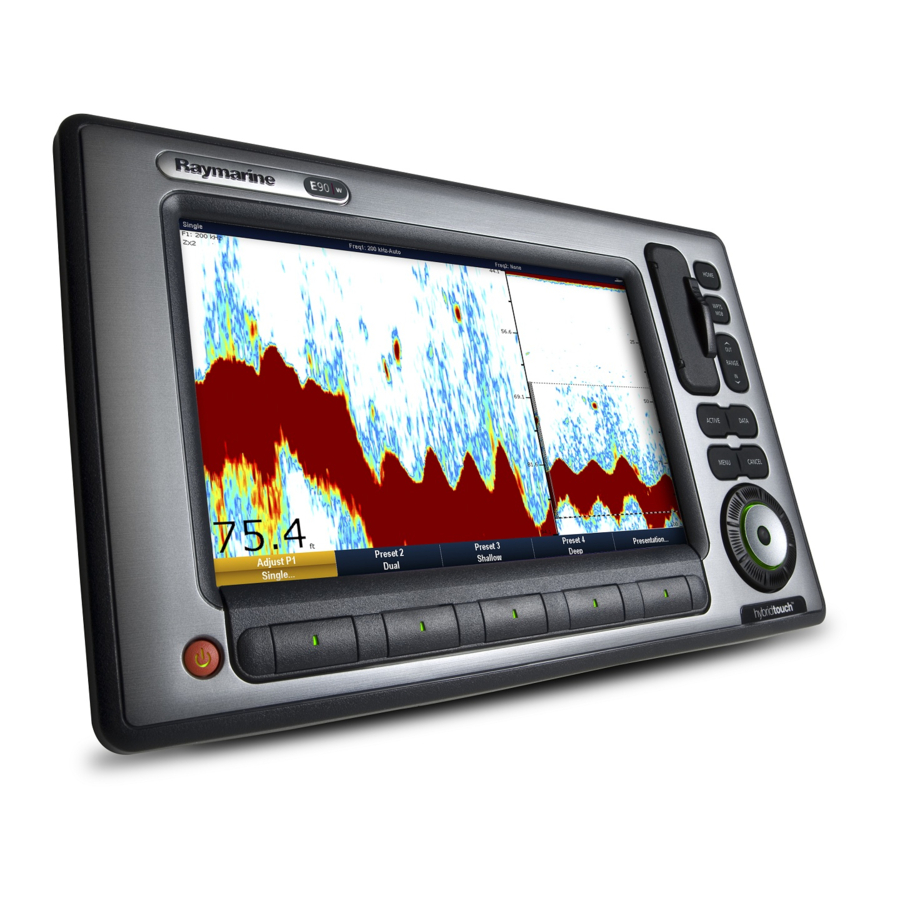
12.1 Fishfinder introduction Fishfinder screen The fishfinder displays a scrolling image of the seabed, updating Warning: Sonar operation from the right as your vessel makes progress. • NEVER operate the sounder with the boat out of Example fishfinder screen the water. •... -
Page 171: The Sonar Image
12.2 The sonar image • Icon static - the fishfinder transducer is connected but not transmitting. Interpreting the seabed using sonar • Icon greyed-out - no fishfinder transducer is connected. It is important to understand how to correctly interpret the seabed How the fishfinder works structure represented in the fishfinder display. - Page 172 Factors influencing the sonar display Water depth As sea depth increases signal strength decreases, resulting in a The quality and accuracy of the display can be influenced by a lighter on-screen image of the bottom. number of factors including vessel speed, depth, object size, background noise and transducer frequency.
-
Page 173: Fishfinder Presets
12.3 Fishfinder presets 1. Press the appropriate softkey to select from: • PRESET 1 SINGLE, The fishfinder provides you with four preset configurations available on the fishfinder toolbar. These enable you to quickly select • PRESET 2 DUAL, appropriate settings tailored for various situations. •... -
Page 174: Fishfinder Display Modes
12.4 Fishfinder display modes When the range increases, the area shown in the zoom window also increases. Selecting a fishfinder display mode Zoom split When a fishfinder preset is selected, its softkey label changes to With the zoom display mode you can split the screen and display ADJUST. - Page 175 Selecting zoom split screen With the fishfinder in zoom mode: 1. Press the ZOOM softkey to select FULL or SPLIT as required. Adjusting the fishfinder zoom factor When the zoom function is active (ZOOM FULL or ZOOM SPLIT), you can either select a predefined zoom factor or adjust it manually. With the fishfinder in zoom mode: 1.
- Page 176 4. Select the SELECT VIEW softkey. Bottom Lock is selected for individual fishfinder windows and can either replace (ON) or appear alongside (SPLIT) the standard 5. Select the A-SCOPE option. fishfinder image. Note: Enabling A-Scope mode automatically switches OFF Enabling Bottom Lock Bottom Lock and Zoom.
-
Page 177: Fishfinder Range
12.5 Fishfinder range The Range and Range Shift functions enable you to change the range of depth displayed by the fishfinder. Range The Range function enables you to define the range of depth that you see in the fishfinder display. By default, the fishfinder display shows the shallowest required range, enabling you to clearly see what is near the surface of the water under your vessel. -
Page 178: Fishfinder Presentation Options
12.6 Fishfinder presentation options Using fishfinder range shift The DSM automatically adjusts the display to keep the bottom in The PRESENTATION softkey gives you access to a features the lower half of the display window. Alternatively you can shift the and functions which enhance the fishfinder display and provide image within the current range. - Page 179 Fishfinder color gain • Medium (Trolling) is a slightly higher gain setting that displays more detail. This is the default mode. You can adjust the color gain to change the signal strength threshold • High (Fishing) provides the most detail, but also displays the for the strongest color in your fishfinder display.
- Page 180 Fishfinder color threshold 4. Use the rotary control to select the amount of Time Varied Gain you want. The color threshold setting determines the range of colors used on 5. Press the OK button. screen. The effect of this is to set a color threshold below which targets are not shown.
- Page 181 Screen item Description Depth Target ID — depths are displayed against recognized targets. The sensitivity of these IDs is directly linked to the Fish Alarm sensitivity; the greater the fish alarm sensitivity, the greater the number of labelled returns. These targets are switched on or off using the Fishfinder Display Setup menu.
- Page 182 Measuring depth and distance using touch If you are in dual frequency mode, you can pause one frequency while the other continues to scroll. This allows you to inspect a From the main fishfinder screen: paused image while the other frequency continues to scroll and 1.
-
Page 183: Fishfinder Waypoints
12.7 Fishfinder waypoints 12.8 Fishfinder alarms Placing a waypoint on the fishfinder display enables you to mark a The display can be configured to provide a number of fishfinder position that you can return to later. alarms. When a waypoint is placed, its details are added to the waypoint list The following fishfinder alarms can be set when you are connected and a vertical line labelled WPT is displayed on screen. -
Page 184: Fishfinder Setup
12.9 Fishfinder setup Opening the fishfinder setup menu In the fishfinder application: 1. Press the MENU button. 2. Select the Fishfinder Setup menu item. E-Series Widescreen User reference... - Page 185 Fishfinder setup menu options This section describes the settings you can change using the fishfinder setup menu. The setup menu contains settings that are likely to be changed infrequently. Menu Item Description Options Configure Preset Frequencies Enables you to adjust the frequencies used for the four fishfinder AUTO or manual frequencies.
- Page 186 Menu Item Description Options Color Palette Various color palettes are available to suit different conditions • Classic Blue and your personal preferences. • Classic Black • Classic White • Sunburst • Greyscale • Inverted Greyscale • Copper • Night Vision Manual Scroll Speed Specify the fishfinder scroll speed.
- Page 187 Changing fishfinder preset names 1. From the main fishfinder screen, press the MENU button. 2. Select Fishfinder Setup from the list of options. 3. Select Configure Preset Frequencies from the list of options. 4. Use the trackpad to select the required preset. 5.
- Page 188 Transducer and DSM settings Selecting the DSM and transducer settings From the main fishfinder screen: 1. Press the MENU button. 2. Select Fishfinder Setup from the list of options. 3. Select from the list of menu options: • Transducer Settings •...
- Page 189 Fishfinder Transducer Calibration Your fishfinder transducer must be calibrated correctly to achieve accurate depth readings. The multifunction display receives the image from a DSM which processes sonar signals from a transducer mounted in the water. If the transducer is equipped with a speed paddle wheel and temperature-sensing thermistor, the DSM calculates speed and temperature.
- Page 190 Menu Item Description Options Frequency Calibration Fine tune the frequency of the transducer. Variable setting for the selected frequency. Depth Offset (waterline) Offset represents the depth of the transducer (relative to the –9.9 to +9.9 feet waterline). Speed Offset Offset applied to the speed log. 0 to 100% Temperature Offset Offset applied to the temperature transducer value.
-
Page 191: Chapter 13 Using The Engine Application
Chapter 13: Using the engine application Chapter contents • 13.1 Engine application overview on page 192 • 13.2 Displaying the engine application on page 192 • 13.3 Setting up the engine application on page 193 • 13.4 Changing the engine panel dial color on page 193 •... -
Page 192: Engine Application Overview
If the default range of data shown by the engine application is not suitable, you can change what is displayed. Note: For details of compatible engines and related software updates, please refer to the Raymarine website at www.raymarine.com. E-Series Widescreen User reference... -
Page 193: Setting Up The Engine Application
13.3 Setting up the engine application 13.4 Changing the engine panel dial color In the engine application: 1. Press the MENU button. In the Engine application: 2. Select Panel Setup Menu . 1. Press the MENU button. 3. Select Number of Engines , then select the appropriate value. 2. -
Page 194: Pre-Configured Data Panels
13.5 Pre-configured data panels By default, a pre-configured range of data is displayed in a number of data ’panels’. Each panel consists of a number of ’cells’, each containing a different item of data. Note: Panel selection is a local setting, and therefore only affects the individual display that you are currently using. - Page 195 List of pre-configured engine panels A range of pre-configured panels show commonly used data. The following table shows the data displayed by each type of panel. Each data item listed in the table below represents a ’cell’. Note: Panel selection is a local setting, and therefore only affects the individual display that you are currently using. It does not affect any networked displays.
-
Page 196: Changing What The Engine Application Displays
13.6 Changing what the engine Changing the size of data panels application displays In the data or engine application: 1. Press the MENU button. In the engine application: 2. Select Panel Setup Menu. 1. Press the MENU button. 3. Select the data panel you want to resize (Configure...). 2. -
Page 197: Chapter 14 Using The Data Application
Chapter 14: Using the data application Chapter contents • 14.1 Data application overview on page 198 • 14.2 Pre-configured data panels on page 199 • 14.3 Trim tab calibration on page 202 • 14.4 Customizing the data application on page 202 Using the data application... -
Page 198: Data Application Overview
14.1 Data application overview The data application displays system and instrument data on your multifunction display. The data application enables you to view numeric data generated by the system. It also shows data from instruments connected to your multifunction display using the NMEA or SeaTalk protocols. E-Series Widescreen User reference... -
Page 199: Pre-Configured Data Panels
14.2 Pre-configured data panels By default, a pre-configured range of data is displayed in a number of data ’panels’. Each panel consists of a number of ’cells’, each containing a different item of data. Note: Panel selection is a local setting, and therefore only affects the individual display that you are currently using. - Page 200 List of pre-configured data panels A range of pre-configured panels show commonly used data. The following table shows the data displayed by each type of panel. Each data item listed in the table below represents a ’cell’. Note: Panel selection is a local setting, and therefore only affects the individual display that you are currently using. It does not affect any networked displays.
- Page 201 Data Navigation panel Waypoint panel Route panel Fishing panel Sailing panel Local Time Sea Temperature Ground Wind App Wind True Wind VMG Wind Selecting a pre-configured data panel In the data or engine application: 1. Using the softkeys, select the pre-configured data panel you want to use.
-
Page 202: Trim Tab Calibration
14.3 Trim tab calibration 14.4 Customizing the data application You can customize the data application to show the system and You can calibrate your trim tabs from your multifunction display. instrument data that you require. Trim tab data can be displayed in the Engine, Data, and CDI In addition to displaying the default, pre-configured data panels in applications by selecting it from the Engine Data Group, using the the data application, you can also customize the data panels to... - Page 203 Note: You can also access the SELECT DATA softkey by pressing and holding the physical softkey associated with the data panel you want to customize (for example, NAVIGATION). Renaming data panels In the data or engine application: 1. Press the MENU button. 2.
- Page 204 E-Series Widescreen User reference...
-
Page 205: Chapter 15 Using The Weather Application (North America Only)
Chapter 15: Using the weather application (North America only) Chapter contents • 15.1 Weather application overview on page 206 • 15.2 Displaying the weather application on page 206 • 15.3 Weather application setup on page 207 • 15.4 Weather application display overview on page 207 •... -
Page 206: Weather Application Overview
By using this service, you release and waive any claims against Sirius Satellite Radio Inc., WSI, Navcast Incorporated, and Raymarine with regard to this service. If you do not have the subscription agreement, you may view a copy on the internet at www.sirius.com/marineweather... -
Page 207: Weather Application Setup
(ESN). This number is located on the weather receiver shipping carton, or on the back of the weather receiver itself. For more information, refer to www.sirius.com. • Your multifunction display must be connected to a Raymarine SR100 Sirius weather receiver. • You must be navigating within US coastal waters. - Page 208 Weather symbols Storm tracks symbols The weather application uses a range of symbols to represent The weather application uses a range of symbols to represent different weather conditions and forecasts. different types of storm tracks. Surface pressure symbols The weather application uses a range of symbols to represent different surface pressure conditions.
- Page 209 Surface observation station symbols Wave information symbols The weather application uses a range of symbols to represent The weather application uses a range of symbols to represent different types of surface obervation station. different types of wave information. Wind speed symbols The weather application uses a range of symbols to represent different wind speeds.
- Page 210 NOWRad precipitation color codes Color code Intensity in mm per hour NOWRad displays the type and level of precipitation: Dark green 4.01 to 12.00 mm/hr Color code Precipitation type Intensity Yellow 12.01 to 24.00 mm/hr Light green Rain (15 to 19 dBz) Orange 24.01 to 50.00 mm/hr Medium green...
-
Page 211: Weather Map Navigation
15.5 Weather map navigation 15.6 Weather reports You can view a number of different weather reports to give you a You can move around the weather map and place waypoints. comprehensive view of the weather. When you open the weather application, a world map is displayed. Your multifunction display shows weather reports for: If the system has a position fix for your boat, the map will be centred on your boat. -
Page 212: Storm Tracking
15.7 Storm tracking Displaying weather reports In the weather application: The storm tracking function enables you to monitor significant 1. Press the WEATHER REPORTS softkey. storms in the area. 2. Select the TROPICAL STATEMENTS, MARINE WARNINGS, Examples of significant storms include tropical disturbances, MARINE ZONE FORECASTS, or WATCHBOX WARNINGS depressions, storms and cyclones, hurricanes, typhoons, and super softkey, as appropriate. -
Page 213: Animated Weather Graphics
15.8 Animated weather graphics You can view animated weather graphics to provide an indication of changing weather patterns. The animated weather option enables you to view an animation from the current time for: • The forecast for wind, wave, or surface pressure. •... - Page 214 E-Series Widescreen User reference...
-
Page 215: Chapter 16 Using Sirius Satellite Radio (North America Only)
Chapter 16: Using Sirius satellite radio (North America only) Chapter contents • 16.1 Sirius radio overview on page 216 • 16.2 Displaying the Sirius radio application on page 216 • 16.3 Sirius radio basic operations on page 217 • 16.4 Sirius radio presets on page 218 •... -
Page 216: Sirius Radio Overview
16.1 Sirius radio overview 16.2 Displaying the Sirius radio application You can use your multifunction display to control a connected Sirius Satellite Radio receiver. With the home screen displayed: Your multifunction display provides access to basic and advanced 1. Select a page that includes the Sirius Satellite Radio application. audio functions on a connected Sirius Satellite Radio receiver. -
Page 217: Sirius Radio Basic Operations
16.3 Sirius radio basic operations Scanning Sirius radio channels In the Sirius Satellite Radio application: You can tune, browse, and scan Sirius Radio channels using your 1. Select the SETUP CHANNELS softkey. multifunction display. 2. Select the SCAN CHANNELS softkey. Tuning and browsing 3. -
Page 218: Sirius Radio Presets
16.4 Sirius radio presets 2. Select the preset you want to delete the channel from. 3. Select the DELETE CHANNEL softkey. You can assign up to 18 Sirius Radio channels to presets to make it easier to find commonly used channels. Moving a Sirius radio channel to another preset Each channel must be assigned to a different preset. -
Page 219: Favorite Sirius Radio Song Alerts
16.5 Favorite Sirius radio song alerts 2. Select the ADD SONG or ADD ARTIST softkey, as appropriate. The song or artist is added as a favorite. The favorites feature alerts you when a favorite song or artist is 3. If you want to add an alert for the song or artist at this time, use playing on any Sirius Radio channel. -
Page 220: Sirius Radio Parental Locking
16.6 Sirius radio parental locking 3. Select the channel you want to block access to. 4. Select the LOCKED option with the CHANNEL You can block certain Sirius Radio channels to prevent unauthorized ENABLED/LOCKED softkey. access. 5. Repeat Steps 3 to 4 for each channel you want to block. When you enable the “Parental Locking”... -
Page 221: Chapter 17 Using Navtex
Chapter 17: Using Navtex Chapter contents • 17.1 Navtex overview on page 222 • 17.2 Navtex setup on page 222 • 17.3 Viewing and managing Navtex messages on page 223 Using Navtex... -
Page 222: Navtex Overview
17.1 Navtex overview 17.2 Navtex setup The Navtex features enable you to view marine safety information, In order to receive Navtex alerts on your multifunction display, you including weather forecasts and marine safety warnings. must connect a Navtex receiver and configure the NMEA options on your multifunction display. -
Page 223: Viewing And Managing Navtex Messages
17.3 Viewing and managing Navtex 4. Set the receive status to ON or OFF, as appropriate. messages 5. Repeat Steps 3 to 4 for each category, as appropriate. Viewing a Navtex message 1. Display the Navtex Message List: i. Press the MENU button. ii. - Page 224 E-Series Widescreen User reference...
-
Page 225: Chapter 18 Using Video
Chapter 18: Using video Chapter contents • 18.1 Video application overview on page 226 • 18.2 Using video on page 227 Using video... -
Page 226: Video Application Overview
18.1 Video application overview You can also output anything displayed on your multifunction display to an external display. The output resolution can be adjusted in the MENU > Display Setup Menu. You can view a video or camera source on your multifunction display. The video application enables you to connect a video source directly Note: You can only view the video on the multifunction display to your multifunction display, and view the video on the screen. -
Page 227: Using Video
18.2 Using video 1. Select the PRESENTATION softkey. 2. Select the CONTRAST, BRIGHTNESS, or COLOR softkey, as Displaying the video application appropriate. 3. Using the trackpad, adjust the level as required. 1. Press the HOME button to display the home screen. 2. - Page 228 E-Series Widescreen User reference...
-
Page 229: Chapter 19 Using The Thermal Camera Application
Chapter 19: Using the thermal camera application Chapter contents • 19.1 Thermal camera application overview on page 230 • 19.2 Camera control on page 231 • 19.3 Image adjustments on page 233 • 19.4 Camera setup on page 236 Using the thermal camera application... -
Page 230: Thermal Camera Application Overview
19.1 Thermal camera application Displaying the thermal camera application overview With the home screen displayed: 1. Select a page icon that includes the thermal camera application. The thermal camera application enables you to control a connected The thermal camera application is displayed. thermal camera and display its image on your multifunction display. -
Page 231: Camera Control
19.2 Camera control Icon Description Scene preset mode for identifying people or objects Thermal camera standby in the water. Standby mode can be used to temporarily suspend the thermal camera’s functions when the camera is not needed for a prolonged Rear-view mode —... - Page 232 Move your finger up and down the screen to tilt the camera UniControl — is used for rotating the camera left or right up or down. (panning), or tilting the camera up or down. Range key— is used to zoom in and out. Move your finger left and right on the screen to rotate the camera left or right (panning).
-
Page 233: Image Adjustments
19.3 Image adjustments 2. Hold the CAMERA HOME softkey for 3 seconds. The “Home” icon flashes on-screen to indicate that a new home Thermal and visible-light operation position has been set. “Dual payload” thermal cameras are equipped with 2 camera lenses Pausing the thermal camera image —... - Page 234 Night Running — scene preset mode for night conditions. Note: Only “dual payload” thermal cameras feature the ability to switch between thermal and visible light. The camera’s “VIS / IR” video cable must be connected to your system if you want to switch between the 2 camera lenses.
- Page 235 The factory default color mode is red, which may improve your night White-hot thermal image. vision. This default mode can be changed if required using the camera’s Video Setup menu. Note: If you have the Disable Color Thermal Video option selected in the camera’s Video Setup menu, only 2 color modes are available —...
-
Page 236: Camera Setup
19.4 Camera setup Thermal camera rear view mode The rear view mode flips the video image horizontally, providing a Accessing the thermal camera setup menu “mirror image”. This is useful for example in instances where the camera is The thermal camera menu provides access to the camera’s rear-facing and you are viewing the image on a forward-facing configuration options. -
Page 237: Chapter 20 Dsc Vhf Radio Integration
Chapter 20: DSC VHF radio integration Chapter contents • 20.1 Using a DSC VHF radio with your display on page 238 • 20.2 Enabling DSC VHF radio integration on page 239 DSC VHF radio integration... -
Page 238: Using A Dsc Vhf Radio With Your Display
20.1 Using a DSC VHF radio with your display You can connect your DSC VHF radio to your multifunction display and show distress message information and GPS position data for other vessels. Connecting a DSC VHF radio to your multifunction display provides the following additional functionality: •... -
Page 239: Enabling Dsc Vhf Radio Integration
20.2 Enabling DSC VHF radio integration To configure your multifunction display to show messages from your DSC VHF radio: 1. Press the MENU button. 2. Select the System Setup menu item. 3. Select the System Integration menu item. 4. Select the ON option for the DSC Message menu item. 5. - Page 240 E-Series Widescreen User reference...
-
Page 241: Chapter 21 Customizing Your Display
Chapter 21: Customizing your display Chapter contents • 21.1 Customizing the vessel icon on page 242 • 21.2 Customizing the databar on page 242 • 21.3 GPS setup on page 243 • 21.4 System setup menu on page 245 Customizing your display... -
Page 242: Customizing The Vessel Icon
21.1 Customizing the vessel icon 21.2 Customizing the databar In the chart application: Moving the databar 1. Press the MENU button. 1. Press the DATA button. 2. Select Chart Setup. 2. Press and hold the DATABAR softkey until the Database Setup 3. -
Page 243: Gps Setup
21.3 GPS setup i. With the Databar Setup Menu displayed, select the Configure menu item. The GPS setup options enable you to configure a connected GPS A red border will appear in the databar, identifying the receiver. currently selected item. ii. - Page 244 Item Description Sky view — a visual representation of the position of tracked satellites. Horizontal Dilution of Position (HDOP) — a measure of GPS accuracy, calculated from a number of factors including satellite geometry, system errors in the data transmission and system errors in the GPS receiver.
-
Page 245: System Setup Menu
21.4 System setup menu The following table describes the various options in the System Setup menu for your multifunction display. Menu item Description Options Boat Details The accurate operation of the collision alarm is dependent on • Minimum Safe Depth you supplying suitable values for the Boat Details setting. - Page 246 Manual Variation setting to specify the • Range: 0 to 30 degrees East or West compensation value that you want to use. This value is also transmitted to any other connected Raymarine instruments. • Language Determines the language that will be used for all on-screen text, labels, menus and options.
- Page 247 Menu item Description Options Settings and Data Reset Resets all system setup menus, including page sets and the Factory Reset confirmation databar, to the factory default settings. Waypoints, routes and • YES tracks ARE deleted. • NO Note: For systems using multiple multifunction displays (networked displays), the complete system database is deleted on the data master (primary display).
- Page 248 Menu item Description Options Distance Units Units Setup Enables you to specify the units used for the following key measurements: • Nautical Miles (default) • Distance • Statute Miles • Speed • Kilometers • Depth Speed Units • Temperature • Knots (default) •...
- Page 249 Menu item Description Options • Liters System Integration Autopilot Control Determines the connection settings for external equipment. The following items are available in the sub-menu: • Disabled (default) • Autopilot Control — If set to Enabled, this option allows you •...
- Page 250 Menu item Description Options to OFF to ensure that all NMEA-connected units receive • OFF heading data from the external heading sensor. • ALL (default) • Keyboard — Set to ONE or ALL if you have an external keyboard connected. Otherwise, set to OFF. •...
- Page 251 Menu item Description Options • WPL • VTG • ZDA NMEA Port Setting • NMEA 4800 (default) • Navtex 4800 • Navtex 9600 • AIS 38400 Enable Password Waypoint Password Setup This menu allows you to enable password protection for waypoints, and to change the password.
- Page 252 E-Series Widescreen User reference...
-
Page 253: Chapter 22 Maintaining Your Display
Chapter 22: Maintaining your display Chapter contents • 22.1 Service and maintenance on page 254 • 22.2 Routine equipment checks on page 254 • 22.3 Cleaning on page 255 • 22.4 Cleaning the display case on page 255 • 22.5 Cleaning the display screen on page 256 Maintaining your display... -
Page 254: Service And Maintenance
22.2 Routine equipment checks This product contains no user serviceable components. Please Raymarine strongly recommends that you complete a number of routine checks to ensure the correct and reliable operation of your refer all maintenance and repair to authorized Raymarine dealers. -
Page 255: Cleaning
22.3 Cleaning 22.4 Cleaning the display case Best cleaning practices. The display unit is a sealed unit and does not require regular cleaning. If it is necessary to clean the unit, follow this basic When cleaning this product: procedure: 1. Switch off the power to the display. •... -
Page 256: Cleaning The Display Screen
22.5 Cleaning the display screen A coating is applied to the display screen. This makes it water repellent, and prevents glare. To avoid damaging this coating, follow this procedure: 1. Switch off the power to the display. 2. Rinse the screen with fresh water to remove all dirt particles and salt deposits. -
Page 257: Chapter 23 Technical Support
Chapter 23: Technical support Chapter contents • 23.1 Raymarine customer support on page 258 • 23.2 3rd party support on page 259 Technical support... -
Page 258: Raymarine Customer Support
Viewing multifunction display software information Raymarine provides a comprehensive customer support service. You can contact customer support through the Raymarine website, 1. Press the MENU button. telephone and email. If you are unable to resolve a problem, please 2. Select System Diagnostics. -
Page 259: 3Rd Party Support
23.2 3rd party support Contact and support details for 3rd party suppliers can be found on the appropriate websites. Navionics www.navionics.com Sirius marine weather www.sirius.com/marineweather Sirius audio www.sirius.com Technical support...
Need help?
Do you have a question about the E Series and is the answer not in the manual?
Questions and answers
Sir, good afternoon, I have Raymarine Radar and MFD ( E70014) , it's not connecting to the Radar , when I simulated data then it contact otherwise it is not connecting. Thanking you Regards Aman
The Raymarine E70014 MFD may not be connecting to the radar due to one or more of the following reasons:
1. Incorrect Connection Type: The radar must be connected using a compatible SeaTalkhs/RayNet cable. If using an RJ45 SeaTalkhs cable, additional accessories may be needed.
2. Improper Network Setup: If the system includes multiple devices, the radar should be connected through a Raymarine network switch. Direct connection is only supported in small systems with one display and no other digital devices.
3. Display Compatibility Limits: The E70014 MFD (a-Series or e7/e7D) supports only one direct SeaTalkhs/RayNet connection. If more devices are connected, a network switch is required.
4. Power Supply Issue: The radar scanner must be powered correctly. Open array scanners require a Voltage Converter Module (VCM).
5. Pairing Not Completed: The radar and display must be properly paired.
6. Cable or Port Issue: Faulty cables, loose connections, or damaged ports can also cause connection failure.
Checking these factors can help identify and resolve the connection issue.
This answer is automatically generated
how to determine production date of my e96 hybrid by serial #