Agilent Technologies U1251B User's And Service Manual
Handheld digital
multimeter
Hide thumbs
Also See for U1251B:
- User's and service manual (193 pages) ,
- Quick start manual (10 pages) ,
- Service note (3 pages)

Related Manuals for Agilent Technologies U1251B


Summary of Contents for Agilent Technologies U1251B
- Page 1 Agilent U1251B and U1252B Handheld Digital Multimeter User’s and Service Guide Agilent Technologies...
- Page 2 FAR 12.211 (Technical Data) and 12.212 (Computer Software) and, for the Department of Defense, DFARS 252.227-7015 (Technical Data - Commercial Items) and DFARS 227.7202-3 (Rights in Commercial Computer Software or Com- puter Software Documentation). Agilent U1251B/U1252B User’s and Service Guide...
-
Page 3: Safety Symbols
In position of a bi-stable push control CAT III Equipotentiality Category III 1000 V overvoltage protection 1000 V Equipment protected throughout by CAT IV double insulation or reinforced Category IV 600 V overvoltage protection 600 V insulation Agilent U1251B/U1252B User’s and Service Guide... -
Page 4: Safety Information
Agilent Technologies assumes no liability for the customer’s failure to comply with these requirements. Agilent U1251B/U1252B User’s and Service Guide... - Page 5 Remove power and do not use the product until safe operation can be verified by service-trained personnel. If necessary, return the product to Agilent Technologies Sales and Service Office for service and repair to ensure the safety features are maintained.
- Page 6 • Never measure voltage when current measurement is selected. • Use only recommended rechargeable battery. Ensure proper insertion of battery in the meter, and follow the correct polarity. • Disconnect test leads from all the terminals during battery charging. Agilent U1251B/U1252B User’s and Service Guide...
- Page 7 Cet appareil ISM est confomre a la this electrical/electronic product in norme NMB-001 du Canada. domestic household waste. The CSA mark is a registered trademark of the Canadian Standards Association. Agilent U1251B/U1252B User’s and Service Guide...
- Page 8 “Monitoring and Control Instrument” product. The affixed product label is as shown below. Do not dispose in domestic household waste To return this unwanted instrument, contact your nearest Agilent Technologies, or visit: www.agilent.com/environment/product for more information. VIII Agilent U1251B/U1252B User’s and Service Guide...
- Page 9 The Declaration of Conformity (DoC) for this instrument is available on the Web site. You can search the DoC by its product model or description. http://regulations.corporate.agilent.com/DoC/search.htm If you are unable to search for the respective DoC, please contact your N O TE local Agilent representative. Agilent U1251B/U1252B User’s and Service Guide...
- Page 10 Agilent U1251B/U1252B User’s and Service Guide...
-
Page 11: Table Of Contents
Contents Getting Started Tutorial Introducing the Agilent U1251B and U1252B Handheld Digital Multimeter Adjusting the Tilt-Stand The Front Panel at a Glance The Rotary Switch at a Glance The Keypad at a Glance The Display at a Glance Selection of Display by Hz Button... - Page 12 Setting Parity Check Setting Data Bit Setting Echo Mode Setting Print Mode Returning to Default Factory Settings Setting the Battery Voltage Setting the DC Filter Maintenance Introduction General Maintenance Replacing the Battery Charging the Battery Agilent U1251B/U1252B User’s and Service Guide...
- Page 13 Adjustment Procedure Finishing the Adjustment To Read the Calibration Count Calibration Errors Specifications DC Specifications U1251B AC Specifications U1252B AC Specifications U1252B AC+DC Specifications Temperature and Capacitance Specifications U1251B & U1252B Frequency Specifications Agilent U1251B/U1252B User’s and Service Guide XIII...
- Page 14 Contents Operating Specifications General Specifications Agilent U1251B/U1252B User’s and Service Guide...
-
Page 15: Getting Started Tutorial
Agilent U1251B and U1252B Handheld Digital Multimeter User’s and Service Guide Getting Started Tutorial Introducing the Agilent U1251B and U1252B Handheld Digital Multimeter Adjusting the Tilt-Stand The Front Panel at a Glance The Rotary Switch at a Glance The Keypad at a Glance... -
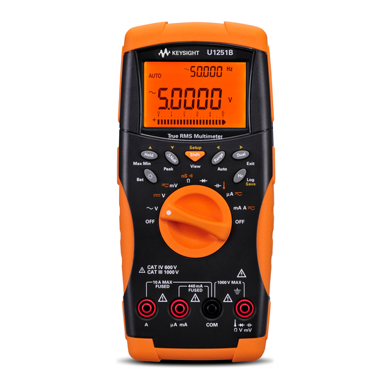
Page 16: Introducing The Agilent U1251B And U1252B Handheld Digital Multimeter
Getting Started Tutorial Introducing the Agilent U1251B and U1252B Handheld Digital Multimeter The handheld digital multimeter’s key features are: • DC, AC and AC + DC (only U1252B) voltage and current measurements. • True- RMS measurement for both AC voltage and current •... -
Page 17: Adjusting The Tilt-Stand
IR-USB cable To PC (host) Tilt-stand at 30 º Agilent U1251B/U1252B User’s and Service Guide... - Page 18 Then flip the stand over so that the stand’s inner surface is facing the meter’s rear. Now, press the stand down into its hinge. Follow the step by step pictorial instructions below. Agilent U1251B/U1252B User’s and Service Guide...
-
Page 19: The Front Panel At A Glance
Getting Started Tutorial The Front Panel at a Glance Display Display Keypad Rotary switch Terminals Agilent U1251B/U1252B User’s and Service Guide... -
Page 20: The Rotary Switch At A Glance
Frequency counter [U1252B only] or Diode Capacitance or Temperature DC µA and AC µA DC mA, DC current, AC mA or AC current Square-wave output, Duty cycle or Pulse width output [for U1252B] and OFF [for U1251B] Agilent U1251B/U1252B User’s and Service Guide... -
Page 21: The Keypad At A Glance
1 ms Peak Hold mode. Press subtracted from subsequent measurements. Press to scroll through Max and Min peak readings. again to see the relative value that has been saved. Agilent U1251B/U1252B User’s and Service Guide... - Page 22 For pulse and duty cycle measurement, press to switch trigger slope to positive or negative. When meter is in peak or dynamic-recording mode, press to restart 1 ms peak hold or dynamic recording mode. Agilent U1251B/U1252B User’s and Service Guide...
-
Page 23: The Display At A Glance
3 For the U1252B only, to set the rotary switch at square wave out position, press only the Dual, Range and Hold buttons or turn the rotary switch to another position. The LCD signs are described on pages 10, 11 and 12. Agilent U1251B/U1252B User’s and Service Guide... - Page 24 Dynamic Recording mode: Minimum value on primary display Dynamic Recording mode: Average value on primary display 1 ms Peak Hold mode: Positive peak value on primary display 1 ms Peak Hold mode: Negative peak value on primary display Agilent U1251B/U1252B User’s and Service Guide...
- Page 25 Duty cycle measurement Pulse width unit µmnF Capacitance units: nF, µF, mF ºC Celsius temperature unit ºF Fahrenheit temperature unit Percentage scale readout proportional to DC 0–20 mA Percentage scale readout proportional to DC 4–20 mA Agilent U1251B/U1252B User’s and Service Guide...
- Page 26 When 4–20 mA% scale or 0–20 mA% scale is indicated on the primary display, the bar graph represents the current value. Agilent U1251B/U1252B User’s and Service Guide...
-
Page 27: Selection Of Display By Hz Button
Frequency measurement mode for current or voltage measurements — voltage or current on secondary display and frequency on primary display. Alternatively, pulse width (ms) or duty cycle (%) can appear on the Agilent U1251B/U1252B User’s and Service Guide... - Page 28 Pulse width (ms) (AC + DC voltage) Duty cycle (%) Frequency (Hz) AC µA Pulse width (ms) (AC Current) [for U1252B] Duty cycle (%) Frequency (Hz) DC µA Pulse width (ms) (DC current) Duty cycle (%) Agilent U1251B/U1252B User’s and Service Guide...
-
Page 29: Selection Of Display By Dual Button
100 [for U1252B] Selection of Display by Dual Button Press to select different combinations of dual display. Normal single display resumes after you press and hold for more than 1 second. See table below. Agilent U1251B/U1252B User’s and Service Guide... - Page 30 Ambient temperature °C or °F DC mV [1] Reading of dBm or dBV depends on the last review on AC V. If the last N O TE review is dBV, the following display will also remain in dBV. Agilent U1251B/U1252B User’s and Service Guide...
- Page 31 [for U1252B] AC + DC mA DC mA Ambient temperature °C or °F AC + DC mA DC A Hz (DC coupling) (DC current) DC A AC A Ambient temperature °C or °F DC A Agilent U1251B/U1252B User’s and Service Guide...
-
Page 32: Selection Of Display By Shift Button
Primary display AC V dBm (in dual display mode) (AC Voltage) dBV (in dual display mode) DC V for U1251B DC V for U1252B AC V (AC + DC Voltage) AC + DC V Agilent U1251B/U1252B User’s and Service Guide... - Page 33 Square wave output for Duty cycle (%) Pulse width (ms) U1252B 1. Press to switch between dBm and dBV measurement. N O TE Press for more than 1 second to return to AC V measurement only. Agilent U1251B/U1252B User’s and Service Guide...
-
Page 34: The Terminals At A Glance
1000 V R.M.S. for short circuit <0.3 A Ω μA . mA 440 mA / 1000 V 30 kA fast-acting fuse 11 A / 1000 V 30 kA fast-acting fuse for U1252B 440 mA / 1000 V fast-acting fuse Agilent U1251B/U1252B User’s and Service Guide... -
Page 35: The Rear Panel At A Glance
Getting Started Tutorial The Rear Panel at a Glance communication port Test probe holders Battery access cover Figure 1-2 Rear panel of U1252B Agilent U1251B/U1252B User’s and Service Guide... - Page 36 Getting Started Tutorial Agilent U1251B/U1252B User’s and Service Guide...
-
Page 37: Making Measurements
Agilent U1251B and U1252B Handheld Digital Multimeter User’s and Service Guide Making Measurements Measuring Voltage Measuring AC voltage Measuring DC voltage Measuring Current μA & mA Measurement % Scale of 4–20 mA A measurement Frequency Counter Measuring Resistance, Conductance and Testing Continuity... -
Page 38: Measuring Voltage
2 Connect the red and black test leads to the input terminals V.mV and COM respectively. 3 Alternatively, press to display frequency on secondary display. 4 Probe the test points and read the display. Agilent U1251B/U1252B User’s and Service Guide... - Page 39 Making Measurements 2 Figure 2-1 Measuring AC voltage Agilent U1251B/U1252B User’s and Service Guide...
-
Page 40: Measuring Dc Voltage
Figure 2-2 Measuring DC voltage 1 Set the rotary switch to 2 Connect the red and black test leads to the input terminals V.mV and COM respectively. 3 Probe the test points and read the display. Agilent U1251B/U1252B User’s and Service Guide... -
Page 41: Measuring Current
2 Connect the red and black test leads to the input terminals µA.mA and COM respectively. 3 Probe the test points in series with the circuit, and read the display. Figure 2-3 Measuring μA and mA current Agilent U1251B/U1252B User’s and Service Guide... -
Page 42: Scale Of 4-20 Ma
500 mA. The % scale for 4–20 mA or 0–20 mA is set to two ranges as follows: % (0–20 or 4–20 mA) Always auto range DC mA Auto or manual range 999.99% 50 mA, 500 mA 9999.9% Figure 2-4 Measuring scale of 4-20 mA Agilent U1251B/U1252B User’s and Service Guide... -
Page 43: A Measurement
2 Connect the red and black test leads to the 10A input terminal A and COM respectively. The meter is set to A measurement automatically when the red test lead is plugged into the A terminal. Figure 2-5 A measurement Agilent U1251B/U1252B User’s and Service Guide... -
Page 44: Frequency Counter
6 The signal is out of range if the reading is still unstable after Step 5. While the secondary display shows “- 1- “, you may scroll through the pulse width (ms), duty cycle (%) and frequency (Hz) measurements by pressing Agilent U1251B/U1252B User’s and Service Guide... - Page 45 Making Measurements 2 Figure 2-6 Measuring frequency Agilent U1251B/U1252B User’s and Service Guide...
-
Page 46: Measuring Resistance, Conductance And Testing Continuity
1 Set the rotary switch to 2 Connect the red and black test leads to the input terminals Ω and COM respectively. 3 Probe the test points (by shunting the resistor) and read the display. Figure 2-7 Measuring resistance Agilent U1251B/U1252B User’s and Service Guide... - Page 47 Making Measurements 2 4 Press to scroll through audible continuity, conductance and resistance tests as shown in Figure 2- Press Shift Audible continuity Press Shift Figure 2-8 Audible continuity, conductance and resistance test. Agilent U1251B/U1252B User’s and Service Guide...
- Page 48 100 GΩ. As the high- resistance readings are susceptible to noise, you can capture the average readings by using the Dynamic Recording mode. Figure 3- 1 on page 47. Agilent U1251B/U1252B User’s and Service Guide...
- Page 49 Making Measurements 2 Figure 2-9 Conductance measurement Agilent U1251B/U1252B User’s and Service Guide...
-
Page 50: Testing Diodes
• The diode is considered shorted if the meter displays approximately 0 V in both forward and reverse bias modes, and the meter beeps continuously. • The diode is considered open if the meter displays “OL” in both forward and reverse bias modes. Agilent U1251B/U1252B User’s and Service Guide... - Page 51 Making Measurements 2 Figure 2-10 Measuring forward bias of diode Agilent U1251B/U1252B User’s and Service Guide...
- Page 52 Making Measurements Figure 2-11 Measuring reverse bias of diode Agilent U1251B/U1252B User’s and Service Guide...
-
Page 53: Measuring Capacitance
2 Connect the red and black test leads to the input terminals and COM respectively. 3 Use the red probe lead on the positive terminal of the capacitor and use the black probe lead on the negative terminal. 4 Read the display. Agilent U1251B/U1252B User’s and Service Guide... -
Page 54: Measuring Temperature
The 0 °C compensation assists in measuring the relative temperature immediately. 1 Turn the rotary switch to position. 2 Press to select the temperature measurement. 3 Plug the thermocouple adapter (with the thermocouple probe connected to it) into the input terminals COM. Agilent U1251B/U1252B User’s and Service Guide... - Page 55 3 After a constant reading is obtained, press to set the reading as the relative reference temperature. 4 Touch the measurement surface with the thermocouple probe. 5 Read the display for the relative temperature. Agilent U1251B/U1252B User’s and Service Guide...
- Page 56 Making Measurements Figure 2-12 Surface temperature measurement Agilent U1251B/U1252B User’s and Service Guide...
-
Page 57: Alerts And Warning During Measurement
The primary display indicates a flashing “A- Err” until the test lead is removed from the A input terminal. See Figure 2- Figure 2-13 Input terminal warning Agilent U1251B/U1252B User’s and Service Guide... -
Page 58: Charge Terminal Alert
5 V and the rotary switch is not set to the corresponding location. The primary display indicates a flashing “Ch.Err” until the lead is removed from the input terminal. See Figure 2- Figure 2-14 Charge terminal alert Agilent U1251B/U1252B User’s and Service Guide... -
Page 59: Features And Functions
Agilent U1251B and U1252B Handheld Digital Multimeter User’s and Service Guide Features and Functions Dynamic Recording Data Hold (Trigger Hold) Refresh Hold Null (Relative) Decibel Display 1 ms Peak Hold Data Logging Manual Logging Interval Logging Reviewing Logged Data Square Wave Output (for U1252B) -
Page 60: Dynamic Recording
• The average value is the true average of all the measured values taken in the Dynamic Recording mode. If an overload is recorded, the averaging function will stop and the average value becomes "OL"(overload). is disabled in Dynamic Recording mode. Agilent U1251B/U1252B User’s and Service Guide... - Page 61 Press Max Min for > 1 sec or press for > 1 sec Press Max Min Press Max Min for > 1 sec or press for > 1 sec Figure 3-1 Dynamic recording mode operation Agilent U1251B/U1252B User’s and Service Guide...
-
Page 62: Data Hold (Trigger Hold)
TRIG flashes before the new value is updated on the display. 3 Press and hold for more than 1 second to quit this mode. Press Press Measurement update Press press for > 1 sec. Figure 3-2 Data hold mode operation Agilent U1251B/U1252B User’s and Service Guide... -
Page 63: Refresh Hold
The hold value is updated until the measuring value is stable. Then stops flashing, lights up and sounds a tone to alert the user. Press again to disable this function. Agilent U1251B/U1252B User’s and Service Guide... - Page 64 • For resistance and diode measurements, the holding value will not be updated if the reading is in “OL” (open state). • The holding value may not be updated when the reading does not reach a stable state for all measurements. Agilent U1251B/U1252B User’s and Service Guide...
-
Page 65: Null (Relative)
• When taking a DC voltage measurement, the thermal effect will influence the accuracy. Short the test leads and press Null once the displayed value is stable in order to zero out the display. Agilent U1251B/U1252B User’s and Service Guide... - Page 66 Features and Functions Press Press Auto-return after 3 seconds Flash Press as NULL is flashing on the display Figure 3-4 Null (relative) mode operation Agilent U1251B/U1252B User’s and Service Guide...
-
Page 67: Decibel Display
The dBm or the dBV measurements can be selected at the ACV position. The selection will be the reference for other voltage measurements. 2 Press for more than 1 second to exit this mode. Agilent U1251B/U1252B User’s and Service Guide... - Page 68 Press Press for > 1 sec. Press for > 1 sec. Press Press Press for > 1 sec. Only when rotary switch is at Press position Press Press Figure 3-5 dBm/dBV display mode operation Agilent U1251B/U1252B User’s and Service Guide...
-
Page 69: Ms Peak Hold
• If you need to re-start the peak recording, press 3 Press for more than 1 second to exit this mode. 4 According to the measurements in Figure 3- 6 on the next page, the crest Factor will be 2.5048/1.768 =1.416. Agilent U1251B/U1252B User’s and Service Guide... - Page 70 Features and Functions Press for > 1 sec. Press Press Start to capture Press Press Start to capture Press Figure 3-6 1 ms peak hold mode operation Agilent U1251B/U1252B User’s and Service Guide...
-
Page 71: Data Logging
The logging index flashes on the secondary display for 3 seconds before returning to normal display. 2 Press again to save the next value into the permanent memory. Agilent U1251B/U1252B User’s and Service Guide... - Page 72 “FULL”, as shown in Figure 3-8. Press for > 1 sec. Auto-return after 3 seconds Figure 3-8 Full Log 3 Press for more than 1 second to exit this mode. Agilent U1251B/U1252B User’s and Service Guide...
-
Page 73: Interval Logging
“FULL” is indicated on the secondary display. 2 Press for more than 1 second to exit this mode. When interval (automatic) logging is enabled, all keypad operations are N O TE disabled, except for the Log function. Agilent U1251B/U1252B User’s and Service Guide... - Page 74 Features and Functions Press for > 1 sec. First interval Press for > 1 sec. Last interval Press for > 1 sec. Last +1 interval Stop logging Figure 3-9 Interval (Automatic) logging mode operation Agilent U1251B/U1252B User’s and Service Guide...
-
Page 75: Reviewing Logged Data
Review mode to clear logged data. 5 Press for more than 1 second to exit mode. During the data review in either manual or interval logging mode, Press for more than one second to clear all the logged values. Agilent U1251B/U1252B User’s and Service Guide... - Page 76 Press View Press Press Press Log to clear all Press Log to clear all for > 1 sec manual logs for > 1 sec interval logs Press View Figure 3-10 Log review mode operation Agilent U1251B/U1252B User’s and Service Guide...
-
Page 77: Square Wave Output (For U1252B)
(ms) on the primary display. 4 Press to adjust the duty cycle. Duty cycle can be set for 256 steps and each step is 0.390625%. The display only indicates the best resolution with 0.001%. Agilent U1251B/U1252B User’s and Service Guide... - Page 78 6 Press to adjust the pulse width. The pulse width can be set for 256 steps and each step is 1/ (256 x Frequency). The display range automatically adjusts in the range of 9.9999~9999.9 ms. Agilent U1251B/U1252B User’s and Service Guide...
- Page 79 Features and Functions Press Press Press Press Figure 3-12 Duty cycle adjustment for square wave output Agilent U1251B/U1252B User’s and Service Guide...
- Page 80 Features and Functions Press Press Set % Press Set % Press Figure 3-13 Pulse width adjustment for square wave Agilent U1251B/U1252B User’s and Service Guide...
-
Page 81: Remote Communication
Agilent Web site. For details on performing PC- meter remote communication, click on Help after launching the Agilent GUI Data Logger Software. Agilent U1251B/U1252B User’s and Service Guide... - Page 82 Features and Functions To PC USB Figure 3-14 Cable connection for remote communication Agilent U1251B/U1252B User’s and Service Guide...
-
Page 83: Changing The Default Setting
Agilent U1251B and U1252B Handheld Digital Multimeter User’s and Service Guide Changing The Default Setting Selecting Setup Mode Setting Data Logging Mode Setting Thermocouple Types (for U1252B) Setting Reference Impedance for dBm Measurement Setting Minimum Frequency Measurement Setting Temperature Unit... -
Page 84: Selecting Setup Mode
See Table 3, “Available setting options in Setup mode,” for details of available options. 3 Press to save changes. These parameters will remain in the non- volatile memory. 4 Press for more than 1 second to exit Setup mode. Agilent U1251B/U1252B User’s and Service Guide... - Page 85 7-bit, 8-bit Sets the data bit length for the remote communi- 8-bit Data bits cation (remote control with PC) ECHO On, OFF Enables the return of characters to the PC when Echo set to On Agilent U1251B/U1252B User’s and Service Guide...
- Page 86 N O TE 2 For d-LoG and rEF menu items, press to select the digit to be adjusted. 3 J-type thermocouple applies to U1252B. 4 To view the menu item, press for more than 1 second. Agilent U1251B/U1252B User’s and Service Guide...
- Page 87 Refresh Hold mode (automatic trigger). When the variation of the measuring value exceeds the setting of the variation count, the Refresh Hold will be ready to trigger. Press Press Press Press Press Figure 4-1 Data hold/Refresh hold setup Agilent U1251B/U1252B User’s and Service Guide...
-
Page 88: Setting Data Logging Mode
2 Set the interval within 0001~9999 seconds to enable interval (automatic) data logging mode. 3 Press to switch between manual and interval data logging setup. Press Press Press Press set interval Press Press Figure 4-2 Data logging setup Agilent U1251B/U1252B User’s and Service Guide... -
Page 89: Setting Thermocouple Types (For U1252B)
The types of thermocouple sensor that can be selected are the J and the K types. The default type is the K type. Press to switch between the J and the K type. Press Figure 4-3 Thermocouple type setup Agilent U1251B/U1252B User’s and Service Guide... -
Page 90: Setting Reference Impedance For Dbm Measurement
Setting Reference Impedance for dBm Measurement The reference impedance can be set from 1 to 9999 . The default value is 50 Press Press Press Press Figure 4-4 Reference impedance for dBm measurement setup Agilent U1251B/U1252B User’s and Service Guide... -
Page 91: Setting Minimum Frequency Measurement
The typical measuring rate defined at the general specification is based on the minimum frequency of 1 Hz. Press Press Press Press Press Figure 4-5 Minimum frequency setup Agilent U1251B/U1252B User’s and Service Guide... -
Page 92: Setting Temperature Unit
• Celsius only (°C on primary display) single display setting • Celsius- Fahrenheit (d- CF) and Fahrenheit- Celsius (d- FC) dual display setting. Primary-Secondary Display can be swapped by pressing N O TE • Fahrenheit only (°F on primary display) single display setting. Agilent U1251B/U1252B User’s and Service Guide... - Page 93 Changing The Default Setting Press Press Press Press Press Figure 4-6 Temperature unit setup Agilent U1251B/U1252B User’s and Service Guide...
-
Page 94: Setting Auto Power Saving Mode
1~99 minutes. To activate the meter after it has “auto power off”, turn the rotary switch to the OFF position, then turn it back on again. • “OFF” disables APF. is indicated on the display during subsequent measurements. Agilent U1251B/U1252B User’s and Service Guide... - Page 95 Changing The Default Setting Press Press Press Press Press Figure 4-7 Auto power saving setup Agilent U1251B/U1252B User’s and Service Guide...
-
Page 96: Setting % Scale Readout
— 4- 20 mA or 0- 20 mA as proportional to 0~100%. The 25% scale readout represents DC 8 mA at 4- 20 mA and DC 5 mA at 0- 20 mA. Press Figure 4-8 % scale readout setup Agilent U1251B/U1252B User’s and Service Guide... -
Page 97: Setting Beep Frequency
Changing The Default Setting Setting Beep Frequency • The driving frequency can be set to 2400, 1200, 600 or 300 Hz. “OFF” disables beep. Press Press Press Press Press Press Figure 4-9 Beep frequency setup Agilent U1251B/U1252B User’s and Service Guide... -
Page 98: Setting Backlit Timer
• The timer can be set to 1~99 seconds. Backlit turns off automatically after the set period. • “0FF” disables turning off backlit automatically. Press Press Press Press Press Figure 4-10 Backlit timer setup Agilent U1251B/U1252B User’s and Service Guide... -
Page 99: Setting Baud Rate
Changing The Default Setting Setting Baud Rate Select the baud rate for remote control. The available settings are 2400, 4800, 9600 and 19200 Hz. Press Press Press Press Press Figure 4-11 Baud rate setup remote control Agilent U1251B/U1252B User’s and Service Guide... -
Page 100: Setting Parity Check
Changing The Default Setting Setting Parity Check Select the parity check for remote control. It can be set to none, even or odd bit. Press Press Press Press Figure 4-12 Parity check setup Agilent U1251B/U1252B User’s and Service Guide... -
Page 101: Setting Data Bit
Changing The Default Setting Setting Data Bit Select the data bit for remote control. It can be set to either 8 or 7 bits. Press Figure 4-13 Data bit setup for remote control Agilent U1251B/U1252B User’s and Service Guide... -
Page 102: Setting Echo Mode
• Echo ON enables the return of characters to the PC in remote communication. • Echo OFF disables the return of characters to the PC. Press Figure 4-14 Echo mode setup for remote control Agilent U1251B/U1252B User’s and Service Guide... -
Page 103: Setting Print Mode
In this mode, the meter automatically sends the newest data to the host continuously but does not accept any commands from thehost. flashes during the Print operation. Press Figure 4-15 Print mode setup for remote control Agilent U1251B/U1252B User’s and Service Guide... -
Page 104: Returning To Default Factory Settings
1 second to reset to the default factory settings except the Temperature setting. • The Reset menu item automatically reverts to Refresh Hold menu item after reset has taken place. Press for > 1 sec. Figure 4-16 Reset setup Agilent U1251B/U1252B User’s and Service Guide... -
Page 105: Setting The Battery Voltage
Changing The Default Setting Setting the Battery Voltage The battery type for the multimeter can be set to either 7.2 V or 8.4 V. Press Figure 4-17 Battery voltage selection Agilent U1251B/U1252B User’s and Service Guide... -
Page 106: Setting The Dc Filter
• When DC filter is enabled, the measurement speed may decrease N O TE during DC voltage measurement. • During AC or Hz measurement (on primary or secondary display), DC filter will be automatically disabled. Agilent U1251B/U1252B User’s and Service Guide... -
Page 107: Maintenance
Agilent U1251B and U1252B Handheld Digital Multimeter User’s and Service Guide Maintenance Introduction General Maintenance Replacing the Battery Charging the Battery Replacing the Fuse Troubleshooting This chapter helps you to troubleshoot a failing handheld digital multimeter. Agilent Technologies... -
Page 108: Introduction
3 Wipe the case with a damp cloth and a mild detergent — do not use abrasives or solvents. Wipe the contacts in each terminal with a clean swab dipped in alcohol. Agilent U1251B/U1252B User’s and Service Guide... -
Page 109: Replacing The Battery
“Charging The Battery”. The procedures for battery replacement are listed below: 1 At the rear panel, turn the screw on the battery cover from the LOCK to the OPEN position (counterclockwise). Agilent U1251B/U1252B User’s and Service Guide... - Page 110 3 Lift the battery cover up. 4 Replace the specified battery. 5 Reverse the above procedures to close the cover. List of compatible batteries for the Agilent U1251B : N O TE • 9V Alkaline non-chargeable battery (ANSI/NEDA 1604A or IEC 6LR61) •...
-
Page 111: Charging The Battery
2 Turn the rotary switch to the position. Connect the power cord to the DC adapter. 3 Plug the Red (+)/ Black (- ) banana terminals of the DC adapter to the and the “COM” terminals Agilent U1251B/U1252B User’s and Service Guide... - Page 112 90%. Condition Battery Voltage Proportional Percentage Trickle (SBY) 6.0 V ~ 8.2 V 0% ~ 100% Under charging 7.2 V ~ 10.0 V 0% ~ 100% Figure 5-1 Battery capacity display as trickle Agilent U1251B/U1252B User’s and Service Guide...
- Page 113 Avoid pressing any button during the self- test. A message is diplayed as shown below. Figure 5-2 Self test Error Condition Secondary Display • No battery in the meter • Battery failing • Battery is full Agilent U1251B/U1252B User’s and Service Guide...
- Page 114 The charging time is limited to not more than 220 minutes. The secondary display will count down the charging time. During charging, no buttons can be pressed. The error message may appear during charging to alert any overcharging of the battery. Agilent U1251B/U1252B User’s and Service Guide...
- Page 115 7 Remove the DC adapter when the C–End message appears on the secondary display. Do not turn the rotary switch before removing the adapter from the terminals. Figure 5-5 Charge end and trickle state Agilent U1251B/U1252B User’s and Service Guide...
- Page 116 Maintenance Press to start charge Error-Full Error Error-Empty Battery can be charged Fully charged Figure 5-6 Battery charging procedures Agilent U1251B/U1252B User’s and Service Guide...
-
Page 117: Replacing The Fuse
10 Refer to the table below for the part number, rate and size of the fuses. Fuse Agilent Part Number Rating Size Type 2110-1400 440mA/1000V 10 mm x 35 mm Fast blow Fuse 2110-1402 11A/1000V 10 mm x 38 mm Agilent U1251B/U1252B User’s and Service Guide... - Page 118 Maintenance Fuse 1 Fuse 2 Figure 5-7 Fuse replacement Agilent U1251B/U1252B User’s and Service Guide...
-
Page 119: Troubleshooting
• Check that the optical side of the cable is connected to the meter and the Fail on Remote control text side of the cover is up. • Check the baud rate, parity, Data bit, Stop bit (default is 9600, n, 8, 1) • Driver install for IR-USB. Agilent U1251B/U1252B User’s and Service Guide... - Page 120 Maintenance Agilent U1251B/U1252B User’s and Service Guide...
-
Page 121: Performance Tests And Calibration
Agilent U1251B and U1252B Handheld Digital Multimeter User’s and Service Guide Performance Tests and Calibration Calibration Overview Recommended Test Equipment Basic Operating Test Test Considerations Performance Verification Tests Calibration Security Calibration Process Adjustments Consideration This chapter contains the performance test procedures and the adjustment procedures. -
Page 122: Calibration Overview
Accuracy specifications are not warranted beyond the 1- year calibration interval. Agilent does not recommend extending calibration intervals beyond 2 years for any application. Agilent U1251B/U1252B User’s and Service Guide... -
Page 123: Adjustment Is Recommended
Agilent recommends that readjustment should be performed during the calibration process for best performance. This will assure that the U1251B/U1252B will remain within the specifications for the next calibration interval. This criterion for the re- adjustment provides the best long–term stability. -
Page 124: Recommended Test Equipment
<1/5 instrument 1 year spec Square Wave Agilent 53131A and Agilent 34401A <1/5 instrument 1 year spec Short Shorting Plug - Dual banana plug with copper <1/5 instrument 1 year spec wire short between 2 terminal Agilent U1251B/U1252B User’s and Service Guide... -
Page 125: Basic Operating Test
ON and OFF. Testing the Display Press the Hold button and turn on the Meter to view all segments of the display. Compare the display with the example in Table 6- Figure 6-1 LCD display Agilent U1251B/U1252B User’s and Service Guide... -
Page 126: Current Terminal Test
It is shown in Figure 55. The primary display will keep flashing unless the test lead is removed from “A” terminal. Before conducting this test, make sure the beep function is not disabled in N O TE setup. Figure 6-2 Input warning Agilent U1251B/U1252B User’s and Service Guide... -
Page 127: Charge Terminal Alert Test
“Ch.Err” until the lead is removed from the terminal. Figure 6-3 Charge terminal alert Before conducting this test, make sure the beep function is not disabled at N O TE setup. Agilent U1251B/U1252B User’s and Service Guide... -
Page 128: Test Considerations
For the DC voltage, DC current, and resistance gain verification measurements, ensure that the calibrator's "0" output is correct. You will need to set the offset for each range of the measuring function being verified. Agilent U1251B/U1252B User’s and Service Guide... -
Page 129: Input Connections
Teflon interconnect cables of minimum length between the calibrator and the multimeter. The cable shields should be earth ground referenced. This configuration is recommended to attain optimal noises and settling time performance during calibration. Agilent U1251B/U1252B User’s and Service Guide... -
Page 130: Performance Verification Tests
If the multimeter fails the performance verification tests, adjustment or repair is required. Make sure you have read the “Test Considerations” on page 114 before N O TE doing the performance verification tests. Agilent U1251B/U1252B User’s and Service Guide... - Page 131 0.48 V, 1 kHz ± 500 mHz ± 500 mHz frequency mode Press button to go to 0.01% – 99.99% 5.0 Vpp @ ± 0.315% ± 0.315% Duty Cycle mode 50%, Square Wave, 50 Hz Agilent U1251B/U1252B User’s and Service Guide...
- Page 132 ± 790 mV 50 V, 100 kHz ± 1.87 V 500 V 500 V, 1 kHz ± 2.25 V 500 V, 10 kHz ± 2.25 V 1000 V 1000 V, 1 kHz ± 8.0 V Agilent U1251B/U1252B User’s and Service Guide...
- Page 133 ± 6.5 mV 1000 mV, 10 kHz ± 12.5 mV ± 6.5 mV 1000 mV, 20 kHz ± 11.5 mV 1000 mV, 30 kHz ± 20.0 mV 1000 mV, 100 kHz ± 47.0 mV Agilent U1251B/U1252B User’s and Service Guide...
- Page 134 ± 0.108 nF position 100.00 nF 100.00 nF ± 1.05 nF ± 1.05 nF 1000.0 nF 1000.0 nF ± 10.5 nF ± 10.5 nF 10.000 μF 10.000 μF ± 0.105 μF ± 0.105 μF Agilent U1251B/U1252B User’s and Service Guide...
- Page 135 ± 3.0 mA Caution: Connect the calibrator to handheld multimeter's A and COM terminals before applying 5A and 10A ± 16 mA ± 16 mA [10] 10 A 10 A ± 40 mA ± 35 mA Agilent U1251B/U1252B User’s and Service Guide...
- Page 136 [6] All frequency counters are susceptible to error when measuring low voltage, low-frequency signals. Shielding inputs from external noise pickup is critical for minimizing measurement errors. [7] Use the Null mode to zero residual Agilent U1251B/U1252B User’s and Service Guide...
- Page 137 After measured current for > 10A, to cool down the meter for 2 times of measuring time you applied before low current measurement [12] For signal frequency greater than 1 kHz, additional 0.1% per kHz to be added to accuracy Agilent U1251B/U1252B User’s and Service Guide...
-
Page 138: Calibration Security
The security code may contain up to 4 numeric characters. “To Unsecure the Instrument Without the Security Code” on page 127 N O TE if you forget your security code. Agilent U1251B/U1252B User’s and Service Guide... -
Page 139: Unsecuring The Instrument For Calibration
4 Use the editing keys to step each character in the code. Use the to select each character. 5 Press (Save) when done. 6 If the correct security code is entered, the secondary display will show PASS. Agilent U1251B/U1252B User’s and Service Guide... - Page 140 5 Press (Save) to store the new calibration security code. 6 If the new calibration security code has been successfully stored, the secondary display will show PASS. Agilent U1251B/U1252B User’s and Service Guide...
- Page 141 7 Set the code, same as the last 4 digits of the instrument’s serial number. 8 Press (Save) to confirm the entry. 9 If the 4 digits entered are correct, the secondary display will show PASS. Agilent U1251B/U1252B User’s and Service Guide...
-
Page 142: Calibration Process
5 Secure the instrument against calibration. 6 Note the new security code and calibration count in the instrument's maintenance records. Make sure to quit the Adjustment Mode before turning off the instrument. N O TE Agilent U1251B/U1252B User’s and Service Guide... -
Page 143: Using The Front Panel For Adjustments
1 Use the edit keys to select each digit in the primary display. 2 Use the and the arrow keys to advance through the digits 0 through 9. 3 Press when done to start calibration. Agilent U1251B/U1252B User’s and Service Guide... -
Page 144: Adjustments Consideration
1 hour with the K- type thermocouple connected between the instrument and the calibration source. Never turn off the instrument during an adjustment. This may delete the CAU T ION calibration memory for the present function. Agilent U1251B/U1252B User’s and Service Guide... -
Page 145: Valid Adjustment Input Values
0.9 to 1.1 x Full Scale Diode 10 nF, 100 nF, 1000 nF, 10 F, 100 Make sure to provide 0 °C µ F, 1000 F, 10 mF / 0 °C with ambient compensation µ µ Agilent U1251B/U1252B User’s and Service Guide... -
Page 146: Adjustment Procedure
7 Enter the actual applied input (see “Entering Adjustment Values” on page 129). 8 Press to start the adjustment. The CAL flashes in the secondary display to indicate that the calibration is in progress. Agilent U1251B/U1252B User’s and Service Guide... - Page 147 Repeat the adjustment procedure. 9 Repeat steps 1 through 8 for each adjustment point. 10 Verify the adjustments using the “Performance Verification Tests” on page 116. Verify the adjustments using Table 6- Agilent U1251B/U1252B User’s and Service Guide...
- Page 148 U1252B), to position short between 2 (for model U1251B) terminals 3.0000 V 3.0000 V 30 V 30.000 V 30.000 V 500V 300 V 300.00 V 300.00 V 1000V 1000 V 1000.0 V 1000.0 V Agilent U1251B/U1252B User’s and Service Guide...
- Page 149 SHort SHort position with copper wire short between 2 terminals 50 mV 30 mV 30.000 mV 30.000 mV 500 mV 300 mV 300.00 mV 300.00 mV 1000 mV 1000 mV 1000.0 mV 1000.0 mV Agilent U1251B/U1252B User’s and Service Guide...
- Page 150 10 M 10.000 M 10.000 M 3.0000 M 3.0000 M 500 k 300 k 300.00 k 300.00 k 50 k 30 k 30.000 k 30.000 k 3.0000 k 3.0000 k 300.00 300.00 Agilent U1251B/U1252B User’s and Service Guide...
- Page 151 0000.0 ºC 0000.0 ºC mode Turn the rotary swich to the OPEN Input terminal oPEn oPEn position open (remove any test leads and Short Plugs from the input terminal) 300.00 300.00 5000 3000 3000.0 3000.0 Agilent U1251B/U1252B User’s and Service Guide...
- Page 152 3 A, 1 kHz 3.0000 A 3.0000 A 10 A, 1 kHz 10.000 A 10.000 A Be sure to recalibrate “Short” using the dual banana plug with copper wire after performing calibration for resistance. Agilent U1251B/U1252B User’s and Service Guide...
-
Page 153: Finishing The Adjustment
Use the following procedure to read the calibration count from the front panel. 1 Press Adjustment Mode. The primary display shows the calibration count. 2 Take note of the count. 3 Press again to exit the calibration count mode. Agilent U1251B/U1252B User’s and Service Guide... -
Page 154: Calibration Errors
Calibration error: Secure code invalid Calibration error: Serial number code invalid Calibration error: Calibration aborted Calibration error: Value out of range Calibration error: Signal measurement out of range Calibration error: Frequency out of range EEPROM write failure Agilent U1251B/U1252B User’s and Service Guide... -
Page 155: Specifications
Agilent U1251B and U1252B Handheld Digital Multimeter User’s and Service Guide Specifications DC Specifications U1251B AC Specifications U1252B AC Specifications U1252B AC+DC Specifications Temperature and Capacitance Specifications U1251B & U1252B Frequency Specifications Operating Specifications General Specifications This chapter lists the specifications of the handheld digital multimeter. -
Page 156: Dc Specifications
440.00 mA 0.01 mA 0.2+5 0.15+5 0.2 V (0.01 Ω) 5.0000 A 0.0001 A 0.3+10 0.3+10 0.4 V (0.01 Ω) 0.001 A 0.3+10 0.3+5 10.000 A 0.1 mV 1.04 mA 0.05 + 5 Diode Test Agilent U1251B/U1252B User’s and Service Guide... - Page 157 [1] Input impedance: Refer to Table 7-6. [2] The accuracy could be 0.05 %+10 for U1251B and 0.05 %+5 for U1252B. Always use the Null function to zero out the thermal effect before measuring the signal. [3] The accuracy of 500 Ω and 5 kΩ is specified after Null function, which is used to subtract the test lead resistance and the thermal effect [4] For the range of 50 Ω/500 MΩ, the R.H.
-
Page 158: U1251B Ac Specifications
Specifications U1251B AC Specifications Table 7-2 U1251B AC Accuracy ± (% of reading + No. of Least Significant Digit) Frequency Function Range Resolution 30 Hz to 45 Hz 45 Hz to 1 kHz 1 kHz to 10 kHz 10 kHz to 30 kHz True RMS 50.000 mV... -
Page 159: U1252B Ac Specifications
[7] Crest factor ≤ 3.0 at full scale, 5.0 at half scale except the 1000 mV and 1000 V ranges where it is 1.5 at full scale, 3.0 at half scale. For non-sinusoidal waveform, add 0.1% of reading ± 0.3% of range. Agilent U1251B/U1252B User’s and Service Guide... -
Page 160: U1252B Ac+Dc Specifications
30 seconds. After measuring current >10 A, leave the meter to cool down for a period that is twice the measuring time used before application of low current measurement. [6] Input current < 3 Arms. Agilent U1251B/U1252B User’s and Service Guide... -
Page 161: Temperature And Capacitance Specifications
(with internal ambient compensation), deviation may show between the readings of the calibrator and the meter, due to differences in ambient compensation between the calibrator and the meter. [2] Only available in U1252B. Agilent U1251B/U1252B User’s and Service Guide... -
Page 162: U1251B & U1252B Frequency Specifications
<600 kHz 9.9999 kHz 0.0001 kHz 99.999 kHz 0.001 kHz 999.99 kHz 0.01 kHz U1251B Frequency Sensitivity During Voltage Measurement Input Range Trigger Level For DC Coupling Minimum Sensitivity (R.M.S. Sine-Wave) (Maximum input for specified 20 Hz – 100 kHz <... - Page 163 Specifications U1251B & U1252B Frequency Sensitivity During Current Measurement Input Range Minimum Sensitivity (R.M.S. Sine-Wave) 20 Hz – 20 kHz 500.00 μA 100 μA 5000.0 μA 250 μA 50.000 mA 10 mA 440.00 mA 25 mA 5.0000 A 10.000 A 2.5 A...
- Page 164 For non-square wave signals, an additional 5 counts need to be added. [3] The minimum measurement frequency of low frequency is set by power-on option to speed up the measurement rate. Agilent U1251B/U1252B User’s and Service Guide...
- Page 165 [3] For signal frequencies greater than 1 kHz, add 0.1% per kHz to the accuracy. [4] The accuracy for duty cycle and pulse width is based on a 5 V square wave input without dividing signal. Agilent U1251B/U1252B User’s and Service Guide...
-
Page 166: Operating Specifications
Times/second ACV + dB AC + DC V Ω/nS Diode 4 (< 100 μF) Capacitance AC + DC I Temperature Frequency 1 (>10 Hz) Duty cycle 0.5 (>10 Hz) Pulse width 0.5 (>10 Hz) Agilent U1251B/U1252B User’s and Service Guide... - Page 167 10.001 MΩ || 10 MΩ [1] For 5 V to 1000 V range, the specified input impedance in parallel with 10 MΩ at dual display. [2] The specified input impedance (nominal) in parallel with <100 pF. Agilent U1251B/U1252B User’s and Service Guide...
-
Page 168: General Specifications
Both primary and secondary displays are 5-digit liquid crystal display (LCD) with maximum reading of 50,000 counts. Automatic polarity indication. Power Consumption • 105 mVA / 420 mVA (with backlit) maximum (U1251B) • 165 mVA / 480 mVA (with backlit) maximum (U1252B) Operating Environment Full accuracy at –20 °C to 55 °C... - Page 169 Specifications Warranty • 3 years for main unit • 3 months for standard accessories unless otherwise specified Agilent U1251B/U1252B User’s and Service Guide...
- Page 170 Specifications Agilent U1251B/U1252B User’s and Service Guide...
- Page 171 Product specifications and descriptions in this document are subject to change without notice. Always refer to the Agilent Web site for the latest revision. © Agilent Technologies, Inc. 2009 Printed in Malaysia First Edition, December 01, 2009 U1251-90036 Agilent Technologies...