Hoval UltraGas 15 Installation Instructions Manual
Condensing gas heating boilers for natural gas and liquid gas for modulating operation
Hide thumbs
Also See for UltraGas 15:
Table of Contents
Advertisement
Technical information
Installation instructions
UltraGas
(15-50)
®
Condensing gas heating boilers
for natural gas and liquid gas
for modulating operation
Hoval products must be installed and commissioned
only by appropriately qualified experts. These instruc-
tions are intended exclusively for the specialist. Electri-
cal installations may only be carried out by a qualified
electrician.
Subject to modifi cations
|
4 210 264 / 04 - 08/13
Rated output levels at 40/30ºC
and for natural gas
30-UltraGas
®
30-UltraGas
®
30-UltraGas
®
30-UltraGas
®
30-UltraGas
®
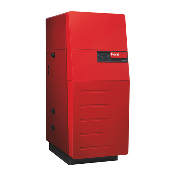
The floor standing gas condensing boiler UltraGas
designed and approved for use as heat generators for
hot water heating systems with a permissible flow tem-
perature of up to 85ºC
, in accordance with EN 483 and
1)
EN 677. They are designed for continuously adjustable
reduced output operation in heating systems.
See technical data
1)
(15)
3,1 - 15,5 kW
(20)
4,0 - 20,2 kW
(27)
5,0 - 27,2 kW
(35)
5,8 - 35,7 kW
(50)
8,3 - 50,1 kW
EN
are
®
Advertisement
Table of Contents

Related Manuals for Hoval UltraGas 15


Summary of Contents for Hoval UltraGas 15
- Page 1 ® 30-UltraGas (50) 8,3 - 50,1 kW ® Hoval products must be installed and commissioned The floor standing gas condensing boiler UltraGas ® only by appropriately qualified experts. These instruc- designed and approved for use as heat generators for tions are intended exclusively for the specialist. Electri-...
-
Page 2: Table Of Contents
Safety instructions Key to symbols used ..........................4 Important notes Acceptance of delivery ........................... 4 Scope of guarantee ..........................4 Instruction manuals ..........................4 Regulations, official permits ........................4 2.4.1 Germany § ..............................5 2.4.2 Austria § ..............................5 2.4.3 Switzerland §... - Page 3 Maintenance Safety information ..........................29 Bleeding ..............................29 Water refilling ............................29 Information for combustion controller/chimney sweep regarding emission monitor key ..... 30 Cleaning ..............................31 7.5.1 Cleaning the burner cylinder ........................31 7.5.2 Cleaning the exterior of the combustion chamber and burner cylinder ........... 32 7.5.3 Cleaning/adjusting the ignition and ionisation device ................
-
Page 4: Safety Instructions
Indicates an immediate hazard to per- A summary of all the instruction manuals sons. relevant to this system can be found in the Hoval System User Guide! In excep- Safety information: tional cases the instructions are kept with Warning of dangerous electrical voltage. -
Page 5: Germany
2.4.1 Germany § 2.4.3 Switzerland § • DIN EN 12831 Heating systems in buildings - • SN EN 12831 Heating systems in buildings - Methods for calculating the design heat load Methods for calculating the design heat load • DIN EN 13384 Flue gas systems - Heat and flow •... -
Page 6: Assembly 3.1 Set-Up, Levelling
Assembly Set-up, levelling The boiler is fixed to wooden transport chocks. For transport up and down stairs, it is wise to leave these timbers in place under the boiler. A special foundation plate for the boiler is not an es- sential, but it is recommended. -
Page 7: Technical Data
The Hoval UltraGas has a vertically utilised for the heating circuit. The gas burner is in the ®... -
Page 8: Technical Data
Technical data UltraGas (15-50) ® Type (15) (20) (27) (35) (50) • Nominal output 80/60°C with natural gas 3,0-14,0 3,8-18,2 4,5-24,5 5,2-32,2 7,5-45,2 • Nominal output 40/30°C with natural gas 3,3-15,5 4,3-20,3 5,0-27,2 5,8-35,7 8,3-50,1 • Nominal output 80/60°C with liquid gas 4,5-13,8 4,9-18,6 6,6-24,3... -
Page 9: Dimensions
Dimensions (Dimensions in mm) Type UltraGas ® (15-27) (35,50) 1 Heating flow / safety flow R 1" R 1¼" 2 Low temperature-return R 1" R 1¼" 2a High temperature-return R 1" R 1¼" 3 Gas connection Rp ¾" Rp ¾" 4 Flue gas outlet DN80 DN80... -
Page 10: Space Requirements
Space requirements (Dimensions in mm) Boiler door incl. burner swings upward and to the left or outward. A = minimum 150 mm * Burner service position front - boiler cleaning from the right A = optimum 300 mm * - Burner service position left - boiler cleaning from the front - Boiler can be placed with the right side di- rectly against the wall... -
Page 11: Boiler-Flow Resistance
Boiler-Flow resistance Brief description of the automatic fir- ing device UltraGas (15-27) ® The automatic firing device BIC960 of the UltraGas only operates in conjunction with the ® TopTronic heating controller ® UG. For this rea- son, the automatic firing device only needs to take care of the last remaining functions to ensure the correct operation of a modulating gas boiler. -
Page 12: Installation
Installation 5.2.2 Room sealed installation Configuration based on a concentric flue system: Safety information • The suction air is supplied through a double-wall flue system. Caution! • Ensure the boiler room is sufficiently ventilated. Sharp edges pose a cutting hazard. Handle the cladding parts with care Configuration using a separating piece (optional): and avoid contact with sharp edges. -
Page 13: Flue Gas Connection And Flue
Flue gas connection and flue Due to the low flue gas temperatures, condensate forms within the flue. For this reason, Hoval gas heating boilers can not be connected to convention- al house chimneys. The flue gas extraction system must comply with the following directives: - DVGW (TRGI) §... -
Page 14: Condensate Drainage
Condensate drainage Possibility 3 - see chapter 5.8 • Siphon and condensate delivery pump • Without neutralisation, condensate discharge into The condensate drainage pipes on higher drain line. the boiler must be made of corro- sion resistant material. The following materials are suitable for condensate drainage: PVC, PE, PP, ABS... -
Page 15: Fitting The Condensate Drain (Standard Design With Siphon)
Fitting the condensate drain (stand- If a neutralisation box is to be fitted, you ard design with siphon) will find the further installation steps on 1. Remove front cover (1a, fig. 06). Release lateral the next page. locking bolt (1, fig. 06) (approx. ¼ turn to the left). Lift the front cover straight upwards and remove towards the front. -
Page 16: Fitting The Neutralisation Box (If Fitted)
Fitting the neutralisation box (if fitted) 5. Fit rear cover (9, fig. 09) of the neutralisation box. 6. Fit jubilee clip (10, fig. 09) approx. 20mm from the upper end of the hose and tighten slightly. 1. Remove the neutralisation box from its pa- The hose (10a, fig. -
Page 17: Fitting The Condensate Delivery Pump
Fitting the condensate delivery pump 8. The hose of the siphon (11, fig. 11) can be easi- ly pushed onto the drain connection of the con- densate drip tray by lifting the neutralisation box 1. Install the condensate delivery pump (10a, fig. -
Page 18: Fitting The Neutralisation Box And The Condensate Delivery Pump
Fitting the neutralisation box and the 4. Remove front cover (1a, fig. 17). Release lateral locking bolt (1, fig. 17) (approx. ¼ turn to the left). condensate delivery pump Lift the front cover straight upwards and remove towards the front. 1. - Page 19 8. Slide the neutralisation box (11, fig. 19) into the 11. Fill the neutralisation box with water. boiler until the hose of the siphon (10a, fig. 18) is 12. Fit the front cover (13, fig. 22) of the neutralisa- directly beneath the drain connection. tion.
-
Page 20: Hydraulic Connection
Regarding suitable hydraulic connections, please - Hydraulic pressure monitor DBmax + 50% observe the notes in the planning documentation - Thermostat of the relevant Hoval sales company! - Temperature monitor TBmax + 20% - Safety temperature limiter Example: UltraGas (15-50) with calorifier and ®... -
Page 21: Electrical Connection
5.11 Electrical connection Procedure to remove the front covering panel 1. Remove front cover (1, fig. 23a), after first releas- ing the lateral locking bolt (1a) (turn approx. ¼ - The electrical connection must be car- turn to the left and pull out as far as the stop). Lift ried out by an approved electrician. -
Page 22: Commissioning
- Maintenance and cleaning work may anti-freeze or anti-corrosion agents, only be performed by trained person- the system is to be thoroughly flushed nel or by the Hoval Customer Service. through several times before refilling Vorsicht! with water. - Danger of damaging the system by fill- ing it with incorrect liquids. -
Page 23: Water Quality
8.3 and 9.5 after 6-12 weeks of heating operation. In particular, attention must be paid to the following stipu- lations: • Hoval boilers and calorifi ers are designed for heating Filling and replacement water plants without signifi cant oxygen intake (plant type I ac- cording to EN 14868). -
Page 24: Bleeding The Air From The Gas Line
Bleeding the air from the gas line § Observe the relevant regulations when bleeding the gas line 1. Open the gas shut-off valve. 2. Bleed the air up to the gas armature. Switching on the system 1. Switch on the main switch on the boiler. Gas inlet pressure The gas flow may only be adjusted and the heating system therefore started up,... -
Page 25: Setting The Gas Flow Rate Co ) And Measurement Of Nox/Co Content In The Flue Gas (Flue Gas Measurement)
Setting the gas flow rate CO ) and 7. Measurement of NOx and CO content. The measured values must meet the limiting values measurement of NOx/CO content in prescribed by the regulations. Values exceeding the flue gas (flue gas measurement) these reference values are an indication of faulty burner setting, gas burner or heat exchanger TorxT40, screwdriver, size 5 and/or allen... -
Page 26: Changing Over To A Different Gas Type
Changing over to a different gas type 5. Set the CO ) content to CO = 9.9 - 10.2 = 5,9 - 5,5) vol% (dry). (flow setting operation as described in section 6.7) This changeover may only be carried out 6. -
Page 27: Record - Activation Of Screed Function
6.10 Record - Activation of screed function Cross where applicable; cut out record and fasten to the control during the active screed function. Minimum requirements for the activation of the screed function: Minimum age cement screed 21 days Minimum age calcium sulphate screed 7 days Flow temperature monitor installed and connected For newly laid screed - see „Recommendation of the Federal Association of Radiant Panel Heating“. - Page 28 Parameter 16 „Screed function“ (Parameter HC, MC1 or MC2) Example: Maximum fl ow temperature 40°C 1 Function heating Starting day + 7 days [°C] VLSol maximal 55°C einstellbar! 55°C maximum set level! 1=Funktionsheizen Funktionsheizen 1 = Function heating START 1 START 9 10 11 12 13 14 15 16 17 18 19 20 21 22 23 24 25 26 TAGE] DAYS...
-
Page 29: Maintenance
Danger of injury for unqualified per- sonnel. Maintenance and cleaning work may only be performed by trained personnel or by the Hoval Customer Service. After repair work respectively exchang- ing boiler parts, a flue gas measurement according to point 6.7 must be carried out imperatively. -
Page 30: Information For Combustion Controller/Chimney Sweep Regarding Emission Monitor Key
Information for combustion controller/chimney sweep regarding emission monitor All other control elements of the control unit are described in the operating instructions. The emission monitor key can also be used to change over to manual operating mode. Emission monitor key / Manual operation To protect under fl oor heating systems against invalid... -
Page 31: Cleaning
The Hoval gas heating boiler should be cleaned and maintained once every year. If the Hoval gas heating boiler was in operation dur- ing the building phase, it will be necessary to carry out a check for cleanliness. If the boiler is dirty, clean Fig. -
Page 32: Cleaning The Exterior Of The Combustion Chamber And Burner Cylinder
7.5.2 Cleaning the exterior of the combustion Cleaning: 9. Spray the combustion chamber and aluFer chamber and burner cylinder tubes (10, fig. 31). The best results are obtained with a spray Warnung! gun with a suitable wide jet nozzle (fan or coni- Chemical burn hazard through cleaning cal jet). -
Page 33: Cleaning/Adjusting The Ignition And Ionisation Device
Reassembly: 7.5.3 Cleaning/adjusting the ignition and ioni- 7. Replace the gasket at the gas connection. sation device 8. Reassemble the burner in reverse order. 9. Check for leaks The distance between the ignition elec- trode and the burner cylinder must be approx. -
Page 34: Clean Siphon Or Neutralisation Box
Clean siphon or neutralisation box Design with neutralisation box (if fitted) 1. Set the main system switch to “0”. 1. Set the main system switch to “0”. 2. Remove the front panel (1, fig. 35). 2. Remove the front panel (1, fig. 34). 3. -
Page 35: Maintenance Of The Neutralisation Equipment (If Available)
Neutralisation granulate for refi lling can be ordered from Hoval under the following item no.: • 1 pack (3 kg) neutralisation granules Part no. 2028 906 Procedure for servicing the neutralisation installation •... -
Page 36: Overview Of Settings
Overview of settings Table of parameters Regulator Setting range / Designation Factory Setting values Type of device: DHW: Address: Surface operation Key : Heating curve HC OFF, 0,20 ..3,5 Heating curve MC1 OFF, 0,20 ..3,5 Heating curve MC2 OFF, 0,20 .. - Page 37 Table for Time programs DHW circuit Time program P1 Time program P2 Time program P3 Cycle 1 Cycle 2 Cycle 3 Cycle 1 Cycle 2 Cycle 3 Cycle 1 Cycle 2 Cycle 3 from from from from from from from from from Direct circuit...
- Page 38 HYDRAULIC Par. Designation Factory Lev. Function allocation of the output DHW charging pump Function allocation of the output Mixer circuit 1 Function allocation of the output Mixer circuit 2 Function allocation of the output Direct circuit Pump Function allocation of the variable output 1 Function allocation of the variable output 2 OFF/ 4/ 43 Function allocation of the variable input 1...
- Page 39 Par. Designation Factory Lev. DHW-NIGHT DHW - economy temperature 40/ 45 °C DHW-legionella protection-day 2:00 DHW-egionella protection-time 50/ 55/ 65/ DHW-legionella protection-temperature 70 °C DHW-temperature recording 50/ 55/ 65/ DHW-maximum temperature limit 70 °C DHW-mode of operation ON/ OFF DHW-tank discharge protection DHW-charging temperature excess 7/ 20 K DHW-switching difference...
- Page 40 MIX. VALVE-1 Par. Designation Factory Lev. Type of reduced operation ECO/ ABS MK= 1,10 Heating system (exponent) Room override (in connection with room sensor) Room factor 100 % Adaptation heating curve Switch-on optimisation Heating limit Room frost protection limit 10 °C Room thermostat function Outside temperature allocation Constant temperature reference value...
- Page 41 MIX. VALVE-2 Par. Designation Factory Lev. Type of reduced operation ECO/ ABS MK= 1,10 Heating system (exponent) Room override (in connection with room sensor) Room factor 100 % Adaptation heating curve Switch-on optimisation Heating limit Room frost protection limit 10 °C Room thermostat function Outside temperature allocation Constant temperature reference value...
- Page 42 HEAT GENER. Par. Designation Factory Lev. H-GEN model 1/ 2/ 5 OFF/ 3 Start-up protection H-GEN 5/ 48/ 65/ 75 Minimum temperature limit H-GEN °C 75/ 85 °C Maximum temperature limit H-GEN Mode of action minimum temperature limit H-GEN Sensor mode operation for H-GEN Minimum burner running time 2 min Burner switching difference I...
-
Page 43: Firing Device Ultragas ® (15-50)
AUTOMATIC FIRING DEVICE UltraGas (15-50) ® Description Blocking temperature °C Maximum setpoint °C Switch-off hysteresis via setpoint °C Switching difference to switch-off point °C Proportional range °C Integral part Differential part Setpoint for bus interrupt °C Maximum temperature rise for low flow temperature °C/s Maximum temperature rise for high flow temperature °C/s... - Page 44 AUTOMATIC FIRING DEVICE UltraGas (15-50) ® Description Ignition (0-> internal, 1-> internal + external, 2-> external) 44 2KM Stepped modulation (0-> off, 1-> rising, 2-> rising and falling) Action mode fault relays ADC/4 value at 0 bar 145/ 145/ 145/ 145/ 145/ *ADC/4 value at 6/10 bar (V3)
- Page 45 RETURN CONTR Par. Designation Factory Lev. Minimum limit return temperature / reference value return 38 °C temperature Switch-off difference Pump follow-on time 1 min SOLAR Par. Designation Factory Lev. 10 K Switch-on difference Switch-off difference Minimum running time SOP 3 min Solar collector maximum temperature 100 °C Solar tank maximum limit (KSPF)
- Page 46 BUFFER Par. Designation Factory Lev. Minimum temperature 5/ 20 °C 95 °C Maximum temperature 8/ 10/ 12K Temperature elevation, H-GEN Switching difference 2/ 5/ 10K Forced discharge Skimming function switch-on difference 10 K Skimming function switch-off difference Start-up protection Discharge protection Buffer mode of operation 2/ 3 Pump follow-on time...
- Page 47 SERVICE Par. Designation Factory Lev. Service 1 (Cleaning ST1 ) Suspend message «CLEANING ST-1» for X days Cleaning according to fi xed date Cleaning according to fi xed interval Cleaning according to cleaning counter Reset cleaning display 1 Service 2 (Cleaning ST2) Suspend message «CLEANING ST-2»...
-
Page 48: Fault Reporting Overview Toptronic ® T
FAULT REPORTING OVERVIEW TopTronic ® Status Designation Fault type Code Remark System External sensor Interruption 10-0 System External sensor Short-circuit 10-1 System Boiler sensor Interruption 11-0 System Boiler sensor Short-circuit 11-1 System Flow sensor 1 Interruption 12-0 MC1=off, YK1=no current System Flow sensor 1 Short-circuit... - Page 49 Regulator with address 10 is System Activity 70-8 missing System Activity Data bus error 70-9 No Hoval regulator System HP return sensor Return min. temp. below setpoint 85-4 System HP return sensor Return max. temp. exceeded 85-5 Heat source min. temp. below...
-
Page 50: Automatic Firing Device (Warning, Blocking, Lock-Out)
Automatic firing device (Warning, Blocking, Lock-out) Code Failure Type Description W:01 Warning Water pressure too low W:02 Warning Ionisation too low B:03 Blocking Gas pressure too low/ Gas pressure switch defective/ external blockings B:04 Blocking *Main gas valve (possibly LPG- valve)/ Heating room fan B:05 Blocking Water pressure outside of limits... - Page 51 4 210 264 / 04...
- Page 52 COPY FOR PLANT USER Confirmation The user (owner) of the system herewith confi rms that • he has received adequate instruction in the operating and maintenance of the installation, • received and taken note of the operating and maintenance instructions and, where applicable other documents con- cerning the heat generator and any further components.
Need help?
Do you have a question about the UltraGas 15 and is the answer not in the manual?
Questions and answers