Advertisement
Available languages
Available languages
Advertisement
Chapters

Related Manuals for Fujitsu FUTRO S900


Summary of Contents for Fujitsu FUTRO S900
- Page 1 Thin Client Operating Manual FUTRO S900...
- Page 2 For automatic driver updates, go to: "http://support.ts.fujitsu.com/com/support/index.html" Should you have any technical questions, please contact: • our Hotline/Service Desk (see the Service Desk list or visit: "http://ts.fujitsu.com/support/servicedesk.html") • Your sales partner • Your sales office We hope you really enjoy using your new Fujitsu system.
- Page 4 You will find more information at "http://ts.fujitsu.com/terms_of_use.html" Order No. Fujitsu Technology Solutions GmbH: A26361-K1050-Z320-2-8N19, edition 1...
- Page 5 FUTRO S900 Operating Manual Deutsch English 简 体 中 文...
- Page 6 FUTRO is a registered trademark of Fujitsu Technology Solutions GmbH. Windows 7, Windows Vista and Windows XP are registered trademarks of Microsoft Corporation. PS/2 is a registered trademark of International Business Machines Corporation (IBM). Kensington is a registered trademark of ACCO World Corporation.
-
Page 7: Table Of Contents
Lautsprecher ausbauen ............. . 28 Fujitsu Technology Solutions... - Page 8 ..............40 Fujitsu Technology Solutions...
-
Page 9: Ihr Futro
Namen von CDs, DVDs sowie Bezeichnungen und Titel von anderen Materialien, z. B.: "CD/DVD Drivers & Utilities" oder Handbuch "Sicherheit/Regularien" Taste kennzeichnet eine Taste auf der Tastatur, z. B: Diese Schrift kennzeichnet Begriffe und Texte, die betont oder hervorgehoben werden, z. B.: Gerät nicht ausschalten Fujitsu Technology Solutions... -
Page 10: Wichtige Hinweise
Versichern Sie sich, dass die Stromaufnahme des Netzadapters nicht höher ist als die des Stromnetzes, an das Sie den Netzadapter anschließen. Ein-/Ausschalter trennen das Gerät nicht von der Netzspannung. Zur vollständigen Trennung von der Netzspannung müssen Sie den Netzstecker aus der Steckdose ziehen. Fujitsu Technology Solutions... -
Page 11: Gerät Transportieren
Spülmittel getaucht und gut ausgewrungen haben. Tastatur und Maus können Sie außen mit Desinfektionstüchern reinigen. Energie sparen, Entsorgung und Recycling Entsorgung Energiesparen Recycling DVDDrivers &Utilities DVDUser Documentation Informationen zu diesen Themen finden Sie auf der DVD "Drivers & Utilities". Fujitsu Technology Solutions... -
Page 12: Fcc Compliance Statement
• Consult the dealer or an experienced radio/TV technician for help. Fujitsu Technology Solutions GmbH is not responsible for any radio or television interference caused by unauthorized modifications of this equipment or the substitution or attachment of connecting cables and equipment other than those specified by Fujitsu Technology Solutions GmbH. -
Page 13: Inbetriebnahme
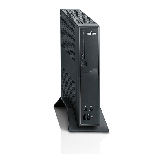
Einschalter Ausschalter Betriebsanzeige SmartCard-Leser Flashspeicherzugriff Kopfhöreranschluss Audioausgang Mikrofonanschluss 1 = SmartCard-Leser 5 = USB-Anschlüsse (Universal Serial Bus) 2 = Anzeige für SmartCard-Leser 6 = Ein-/Ausschalter 3 = Flashspeicherzugriff 7 = Kopfhöreranschluss, Audioausgang (Line Out) 4 = Mikrofonanschluss Fujitsu Technology Solutions... -
Page 14: Rückansicht
2 = Audioausgang (Line Out) 10 = RJ45-LAN-Anschluss (Local Area 3 = PS/2-Tastaturanschluss Network) 4 = USB-Anschlüsse 11 = PS/2-Mausanschluss 5 = DisplayPort 12 = Audioeingang (Line In) 6 = DVI-I-Bildschirmanschluss 13 = PCI/PCIe-Steckplatz 7 = Gleichspannungsbuchse (DC IN) Fujitsu Technology Solutions... -
Page 15: Gerät Aufstellen
Gehen Sie wie folgt vor, um das Gerät in senkrechter Betriebslage zu betreiben: ► Lösen Sie gegebenfalls die Leitungen. ► Schieben Sie das Gerät in Pfeilrichtung auf den Standfuß. ► Stecken Sie gegebenenfalls die zuvor gelösten Leitungen wieder. Fujitsu Technology Solutions... -
Page 16: Waagerechte Betriebslage
► Legen Sie das Gerät auf einer stabilen, ebenen und sauberen Unterlage auf die Oberseite. ► Positionieren Sie die Standfüße auf der Unterseite des Geräts. ► Schrauben Sie die Standfüße mit den Schrauben (1) fest. ► Stecken Sie gegebenenfalls die zuvor gelösten Leitungen wieder. Fujitsu Technology Solutions... -
Page 17: Externe Geräte Anschließen
Leitungen lösen ► Alle betroffenen Geräte ausschalten. Leitung ► Die Netzstecker aller betroffenen Geräte aus den Schutzkontakt-Steckdosen ziehen. ► Alle Datenübertragungsleitungen aus den Steckvorrichtungen der Daten-/Fernmeldenetze ziehen. ► Alle Leitungen am Gerät und an den externen Geräten lösen. Fujitsu Technology Solutions... -
Page 18: Anschlüsse Am Gerät
► Bereiten Sie den Bildschirm vor, wie in der Betriebsanleitung zum Bildschirm beschrieben (z. B. Leitungen stecken). Bildschirm ► Schließen Sie die Datenleitung am gewünschten Bildschirmanschluss Ihres Geräts an. ► Schließen Sie die Netzleitung des Bildschirms an eine geerdete Schutzkontakt-Steckdose an. Fujitsu Technology Solutions... -
Page 19: Maus Anschließen
► Stecken Sie den rechteckigen Stecker der Tastaturleitung in die rechteckige Buchse an der Unterseite oder an der Rückseite der Tastatur. ► Stecken Sie den runden Stecker der Tastaturleitung in den Tastaturanschluss des Geräts. Tastatur ► Schalten Sie Ihr Gerät wieder ein. Fujitsu Technology Solutions... -
Page 20: Externe Geräte An Die Serielle Schnittstelle Anschließen
Software benötigt, installieren Sie diese von dem Datenträger, der mit dem USB-Gerät geliefert wurde. Um die Übertragungsleistung von USB 2.0 zu gewährleisten, darf die Leitung vom externen USB-Gerät zum USB-Anschluss Ihres Geräts nicht länger als 3 m sein. Fujitsu Technology Solutions... -
Page 21: Mikrofon / Kopfhörer / Line-Out- Und Line-In-Geräte Anschließen
► Schließen Sie die Netzadapterleitung an das Gerät an. ► Schließen Sie die Netzleitung an den Netzadapter an. ► Schließen Sie die Netzleitung an eine geerdete Schutzkontakt-Steckdose an. Gerät an das Netzwerk (LAN) anschließen ► Schließen Sie die 10/100/1000-Base-T-Netzleitung an den RJ45-LAN-Anschluss an. Fujitsu Technology Solutions... -
Page 22: Bedienung
Das Boot-Menü wird angezeigt. ► Wählen Sie die gewünschte Boot-Möglichkeit. Konfigurationsmenü des PXE-Systemstarts aufrufen ► Drücken Sie die Tastenkombination ↑ , während Realtek RTL8139(X)/8130/810X Boot Agent angezeigt wird. Auf dem Bildschirm erscheint folgende oder eine ähnliche Anzeige: Fujitsu Technology Solutions... -
Page 23: Boot Order
Gibt die Zeit in Sekunden an, die die folgende Meldung während des Message Systemstarts zu sehen ist: Time: Realtek RTL8139(X)/8130/810X Boot Agent Press Shift-F10 to configure ……. Die Einstellungen sind erst nach dem Abspeichern und einem erneuten PXE-Systemstart wirksam. Fujitsu Technology Solutions... -
Page 24: Systemerweiterungen
Temperatur der Komponenten im Betrieb nicht überschritten wird. Eventuell ist für eine Systemerweiterung oder Hardware-Hochrüstung ein Update des BIOS notwendig. Weitere Informationen finden Sie in der Hilfe zum BIOS oder gegebenenfalls im Technischen Handbuch zum Mainboard. Fujitsu Technology Solutions... -
Page 25: Hinweise Zu Baugruppen
Verwendete Geräte und Werkzeuge müssen frei von statischer Aufladung sein. • Fassen Sie die Baugruppen nur am Rand oder, falls vorhanden, an grün markierten Stellen (TouchPoints) an. • Berühren Sie keine Anschluss-Stifte oder Leiterbahnen auf der Baugruppe. Fujitsu Technology Solutions... -
Page 26: Gehäuse Öffnen
Stecken Sie den Netzstecker erst wieder an, wenn Sie das Gehäuse geschlossen haben. ► Entfernen Sie störende, gesteckte Leitungen. ► Lösen Sie die Schrauben auf der Rückseite (1). ► Schieben Sie den Gehäusedeckel in Pfeilrichtung (2). ► Heben Sie den Gehäusedeckel ab (3). Fujitsu Technology Solutions... -
Page 27: Gehäuse Schließen
"Hinweise zu Baugruppen", Seite 19 - Deutsch. Speichermodul ausbauen ► Drücken Sie die beiden Halteklammern vorsichtig nach außen (1). Speichererweiterung Speichermodul Das Speichermodul klappt nach oben (2). ► Ziehen Sie das Speichermodul in Pfeilrichtung aus dem Einbauplatz (3). Fujitsu Technology Solutions... -
Page 28: Speichermodul Einbauen
22 - Deutsch Systemerweiterungen Speichermodul einbauen ► Setzen Sie das Speichermodul mit den Anschlusskontakten und der Aussparung (a) voran in den Einbauplatz (1). Speichererweiterung Speichermodul ► Klappen Sie das Speichermodul vorsichtig nach unten, bis es spürbar einrastet (2). Fujitsu Technology Solutions... -
Page 29: Smartcard-Leser Ein- Und Ausbauen
► Wenn eine PCI- oder PCIe-Baugruppe eingebaut ist, bauen Sie Traverse und PCI- oder PCIe-Baugruppe aus (siehe "Baugruppe ausbauen", Seite 38 - Deutsch). ► Setzen Sie die Halterung für den SmartCard-Leser in das Gehäuse (1). ► Befestigen Sie die Halterung mit der Schraube (2). Fujitsu Technology Solutions... - Page 30 ► Bauen Sie bei Bedarf die Traverse und die PCI- oder PCIe-Baugruppe wieder ein (siehe "Baugruppe einbauen", Seite 36 - Deutsch). ► Schließen Sie das Gehäuse (siehe "Gehäuse schließen", Seite 21 - Deutsch). Achten Sie darauf, dass die Leitungen nicht zwischen Gehäuse und Bauteilen eingeklemmt werden! Fujitsu Technology Solutions...
-
Page 31: Smartcard-Leser Ausbauen
► Bauen Sie bei Bedarf die Traverse und die PCI- oder PCIe-Baugruppe wieder ein (siehe "Baugruppe einbauen", Seite 36 - Deutsch). ► Schließen Sie das Gehäuse (siehe "Gehäuse schließen", Seite 21 - Deutsch). Achten Sie darauf, dass die Leitungen nicht zwischen Gehäuse und Bauteilen eingeklemmt werden! Fujitsu Technology Solutions... -
Page 32: Lautsprecher Ein- Und Ausbauen (Optional)
► Wenn eine PCI- oder PCIe-Baugruppe eingebaut ist, bauen Sie Traverse und PCI- oder PCIe-Baugruppe aus (siehe "Baugruppe ausbauen", Seite 38 - Deutsch). ► Befestigen Sie die mitgelieferten Sechskantbolzen in den Schraublöchern (1) ► Setzen Sie den Lautsprecher wie abgebildet in das Gehäuse. Fujitsu Technology Solutions... - Page 33 ► Bauen Sie bei Bedarf die Traverse und die PCI- oder PCIe-Baugruppe wieder ein (siehe "Baugruppe einbauen", Seite 36 - Deutsch). ► Schließen Sie das Gehäuse (siehe "Gehäuse schließen", Seite 21 - Deutsch). Achten Sie darauf, dass die Leitungen nicht zwischen Gehäuse und Bauteilen eingeklemmt werden! Fujitsu Technology Solutions...
-
Page 34: Lautsprecher Ausbauen
► Heben Sie den Lautsprecher aus dem Gehäuse. ► Bauen Sie bei Bedarf die Traverse und die PCI- oder PCIe-Baugruppe wieder ein (siehe "Baugruppe einbauen", Seite 36 - Deutsch). ► Schließen Sie das Gehäuse (siehe "Gehäuse schließen", Seite 21 - Deutsch). Fujitsu Technology Solutions... -
Page 35: Wlan-Modul Ein- Und Ausbauen (Optional)
► Befestigen Sie das WLAN-Modul mit den Schrauben (3). ► Schließen Sie die Leitung des WLAN-Moduls am Stecker auf dem Mainboard an (4). ► Bauen Sie bei Bedarf die Traverse und die PCI- oder PCIe-Baugruppe wieder ein (siehe "Baugruppe einbauen", Seite 36 - Deutsch). Fujitsu Technology Solutions... - Page 36 ► Setzen Sie die WLAN-Abdeckung auf das WLAN-Modul (1) und befestigen Sie sie mit den Schrauben (2). ► Schließen Sie das Gehäuse (siehe "Gehäuse schließen", Seite 21 - Deutsch). Achten Sie darauf, dass die Leitungen nicht zwischen Gehäuse und Bauteilen eingeklemmt werden! Fujitsu Technology Solutions...
-
Page 37: Wlan-Modul Ausbauen
"Gehäuse öffnen", Seite 20 - Deutsch). ► Lösen Sie die Schrauben (1) und entfernen Sie die WLAN-Abdeckung (2). ► Wenn eine PCI- oder PCIe-Baugruppe eingebaut ist, bauen Sie Traverse und PCI- oder PCIe-Baugruppe aus (siehe "Baugruppe ausbauen", Seite 38 - Deutsch). Fujitsu Technology Solutions... - Page 38 ► Bauen Sie bei Bedarf die Traverse und die PCI- oder PCIe-Baugruppe wieder ein (siehe "Baugruppe einbauen", Seite 36 - Deutsch). ► Schließen Sie das Gehäuse (siehe "Gehäuse schließen", Seite 21 - Deutsch). Achten Sie darauf, dass die Leitungen nicht zwischen Gehäuse und Bauteilen eingeklemmt werden! Fujitsu Technology Solutions...
-
Page 39: Power-Over-Ethernet-Modul Ein- Und Ausbauen (Optional)
"Gehäuse öffnen", Seite 20 - Deutsch). ► Wenn eine PCI- oder PCIe-Baugruppe eingebaut ist, bauen Sie Traverse und PCI- oder PCIe-Baugruppe aus (siehe "Baugruppe ausbauen", Seite 38 - Deutsch). ► Brechen Sie die Blende (1) aus dem Gehäuse. Fujitsu Technology Solutions... - Page 40 ► Bauen Sie bei Bedarf die Traverse und die PCI- oder PCIe-Baugruppe wieder ein (siehe "Baugruppe einbauen", Seite 36 - Deutsch). ► Schließen Sie das Gehäuse (siehe "Gehäuse schließen", Seite 21 - Deutsch). Achten Sie darauf, dass die Leitungen nicht zwischen Gehäuse und Bauteilen eingeklemmt werden! Fujitsu Technology Solutions...
-
Page 41: Power-Over-Ethernet-Modul Ausbauen
► Bauen Sie bei Bedarf die Traverse und die PCI- oder PCIe-Baugruppe wieder ein (siehe "Baugruppe einbauen", Seite 36 - Deutsch). ► Schließen Sie das Gehäuse (siehe "Gehäuse schließen", Seite 21 - Deutsch). Achten Sie darauf, dass die Leitungen nicht zwischen Gehäuse und Bauteilen eingeklemmt werden! Fujitsu Technology Solutions... -
Page 42: Pci- Oder Pcie-Baugruppe Ein- Und Ausbauen
► Nehmen Sie an der Baugruppe die erforderlichen Einstellungen vor. ► Öffnen Sie das Gehäuse (siehe "Gehäuse öffnen", Seite 20 - Deutsch). ► Stecken Sie die Risercard in ihren Steckplatz (1). ► Lösen Sie die Schraube und entfernen Sie die Rückseitenabdeckung des Einbauplatzes (2). Fujitsu Technology Solutions... - Page 43 ► Stecken Sie die Baugruppe in die Risercard (1). ► Befestigen Sie die Baugruppe mit der Schraube (2). ► Bauen Sie die Traverse ein (3). ► Schließen Sie das Gehäuse (siehe "Gehäuse schließen", Seite 21 - Deutsch). Fujitsu Technology Solutions...
-
Page 44: Baugruppe Ausbauen
EMV-Vorschriften (Vorschriften zur elektromagnetischen Verträglichkeit) wieder einbauen. ► Bauen Sie die Rückseitenabdeckung wieder ein, indem Sie diese von innen in den Einbauplatz setzen und mit der Schraube befestigen. ► Schließen Sie das Gehäuse (siehe "Gehäuse schließen", Seite 21 - Deutsch). Fujitsu Technology Solutions... -
Page 45: Lithium-Batterie Tauschen
Die Batterie springt etwas aus der Halterung heraus. ► Entfernen Sie die Batterie (2). ► Schieben Sie die neue Lithium-Batterie des identischen Typs in die Halterung (3) und drücken Sie sie nach unten, bis sie einrastet. ► Befestigen Sie die Rastnase (4). Fujitsu Technology Solutions... -
Page 46: Technische Daten
Elektrische Daten Nennspannung: 100 - 240 V Max. Nennstrom: 1,2 A Nennfrequenz: 50 - 60 Hz Es dürfen nur folgende Adapter mit Limited Power Source verwendet werden: • S26113-E578-V55-1 Model: ADP-40PH AD • S26113-E557-V55 Model: ADP-65JH AD Fujitsu Technology Solutions... - Page 47 Removing the loudspeaker ............28 Fujitsu Technology Solutions...
- Page 48 ............... . 40 Fujitsu Technology Solutions...
-
Page 49: Your Futro
Names of CDs, DVDs and titles or designations for other materials, e.g.: "CD/DVD Drivers & Utilities" or "Safety/Regulations" manual indicates a key on the keyboard, e.g: This font indicates terms and texts that are emphasised or highlighted, e.g.: Do not switch off the device Fujitsu Technology Solutions... -
Page 50: Important Notes
If the device is brought from a cold environment into the room where it will be used, condensation may occur. Before operating the device, wait until it is absolutely dry and has reached approximately the same temperature as the installation site. Fujitsu Technology Solutions... -
Page 51: Cleaning The Device
Use disinfectant wipes to clean the keyboard and the mouse. Energy saving, disposal and recycling Disposal Energysaving Recycling Drivers& UtilitiesDVD User DocumentationDVD Further information can be found on the "Drivers & Utilities" DVD. Fujitsu Technology Solutions... -
Page 52: Fcc Compliance Statement
• Consult the dealer or an experienced radio/TV technician for help. Fujitsu Technology Solutions GmbH is not responsible for any radio or television interference caused by unauthorized modifications of this equipment or the substitution or attachment of connecting cables and equipment other than those specified by Fujitsu Technology Solutions GmbH. -
Page 53: Getting Started
1 = SmartCard reader 5 = USB ports (Universal Serial Bus) 2 = Indicator for SmartCard reader 6 = ON/OFF switch 3 = Flash memory access 7 = Headphones port, audio output (Line Out) 4 = Microphone jack Fujitsu Technology Solutions... -
Page 54: Rear View
3 = PS/2 keyboard port 11 = PS/2 mouse port 4 = USB ports 12 = Audio input (Line In) 5 = DisplayPort 13 = PCI/PCIe slot 6 = DVI-I monitor port 7 = DC input jack (DC IN) Fujitsu Technology Solutions... -
Page 55: Setting Up The Device
Proceed as follows to operate the device in the vertical operating position: ► Disconnect the cables if required. ► Push the device onto the foot in the direction of the arrow. ► If necessary, reconnect any cables that were previously disconnected. Fujitsu Technology Solutions... -
Page 56: Horizontal Operating Position
► Place the device on its upper side on a sturdy, flat and clean surface. ► Position the base feet on the underside of the device. ► Screw on the base feet with the screws (1). ► If necessary, reconnect any cables that were previously disconnected. Fujitsu Technology Solutions... -
Page 57: Connecting External Devices
► Switch off all affected devices. Cable, ► Remove all power plugs from the grounded mains outlets. ► Unplug all data communication cables from the appropriate sockets. ► Disconnect all of the cables from the device and from the external devices. Fujitsu Technology Solutions... -
Page 58: Ports On The Device
► Follow the instructions contained in the monitor manual to prepare the monitor for operation (e.g. connecting cables). Monitor, ► Connect the data cable to the required monitor port on your device. ► Plug the monitor power cable into the grounded mains outlet. Fujitsu Technology Solutions... -
Page 59: Connecting The Mouse
► Plug the rectangular connector of the keyboard cable into the rectangular socket on the underside or on the rear of the keyboard. ► Plug the round plug of the keyboard cable into the keyboard port on the device. Keyboard, ► Switch your device on again. Fujitsu Technology Solutions... -
Page 60: Connecting External Devices To The Serial Interface
USB device. To ensure the transmission capacity of USB 2.0, the cable from the external USB device to the USB port of your device must not be longer than 3 m. Fujitsu Technology Solutions... -
Page 61: Connecting Microphone, Headphones, Line-Out And Line-In Devices
► Connect the power cable to the mains adapter. ► Plug the power cable into a grounded mains outlet. Connecting the device to the network (LAN) ► Connect the 10/100/1000 Base T network cable to the RJ45 LAN port. Fujitsu Technology Solutions... -
Page 62: Operation
► Select the desired boot option. Calling the PXE system boot configuration menu ► Press the key combination ↑ while Realtek RTL8139(X)/8130/810X Boot Agent is displayed. The following or a similar display appears on the screen: Fujitsu Technology Solutions... - Page 63 Indicates the time in seconds for which the following message is Message displayed during the system boot: Time: Realtek RTL8139(X)/8130/810X Boot Agent Press Shift-F10 to configure ……. The settings are not effective until after saving and another PXE system boot. Fujitsu Technology Solutions...
-
Page 64: System Expansions
An update of the BIOS may be required for a system expansion or hardware upgrade. Further information can be found in the BIOS help section or if necessary in the Technical Manual for the mainboard. Fujitsu Technology Solutions... -
Page 65: Information About Boards
The equipment and tools you use must be free of static charges. • Only touch or hold the boards by the edge or, if present, at the areas marked green (Touch Points). • Never touch pins or conductors on boards fitted with ESDs. Fujitsu Technology Solutions... -
Page 66: Opening The Casing
► Remove any connected wires which are in the way. ► Loosen the screws at the rear (1). ► Slide the casing cover in the direction of the arrow (2). ► Lift off the casing cover (3). Fujitsu Technology Solutions... -
Page 67: Closing The Casing
Removing memory modules ► Carefully push the two mounting clips outwards (1). Memory expansion Memory module The memory module snaps upwards (2). ► Pull the memory module out of its slot in the direction of the arrow (3). Fujitsu Technology Solutions... -
Page 68: Installing A Memory Module
Installing a memory module ► Insert the memory module with the contacts and the recess (a) facing the slot (1). Memory expansion Memory module ► Carefully push the memory module downwards until you feel it click into place (2). Fujitsu Technology Solutions... -
Page 69: Installing And Removing Smartcard Reader
► If a PCI or PCIe board is installed, remove the cross piece and PCI or PCIe board (see "Removing the board", Page 38 - English). ► Place the carrier for the SmartCard reader in the casing (1). ► Fasten the carrier with the screw (2). Fujitsu Technology Solutions... - Page 70 ► Reinstall the cross piece and the PCI or PCIe board if necessary (see "Installing the board", Page 36 - English). ► Close the casing (see "Closing the casing", Page 21 - English). Make sure that the cables are not trapped between the casing and the components. Fujitsu Technology Solutions...
-
Page 71: Removing The Smartcard Reader
► Reinstall the cross piece and the PCI or PCIe board if necessary (see "Installing the board", Page 36 - English). ► Close the casing (see "Closing the casing", Page 21 - English). Ensure that cables are not trapped between the casing and the components. Fujitsu Technology Solutions... -
Page 72: Installing And Removing The Loudspeaker (Optional)
► If a PCI or PCIe board is installed, remove the cross piece and PCI or PCIe board (see "Removing the board", Page 38 - English). ► Secure the hexagon head bolts provided into the screw holes (1). ► Insert the loudspeaker into the housing as illustrated. Fujitsu Technology Solutions... - Page 73 ► Reinstall the cross piece and the PCI or PCIe board if necessary (see "Installing the board", Page 36 - English). ► Close the housing (see "Closing the casing", Page 21 - English). Ensure that the cables are not trapped between the housing and the components. Fujitsu Technology Solutions...
-
Page 74: Removing The Loudspeaker
► Lift the loudspeaker out of the housing. ► Reinstall the cross piece and the PCI or PCIe board if necessary (see "Installing the board", Page 36 - English). ► Close the housing (see "Closing the casing", Page 21 - English). Fujitsu Technology Solutions... -
Page 75: Installing And Removing A Wlan Module (Optional)
► Secure the WLAN module with the screws (3). ► Connect the cable of the WLAN module to the connector on the mainboard (4). ► Reinstall the cross piece and the PCI or PCIe board if necessary (see "Installing the board", Page 36 - English). Fujitsu Technology Solutions... - Page 76 ► Place the WLAN cover on the WLAN module (1) and fasten it with the screws (2). ► Close the casing (see "Closing the casing", Page 21 - English). Make sure that the cables are not trapped between the casing and the components. Fujitsu Technology Solutions...
-
Page 77: Removing The Wlan Module
► Undo the screws (1) and remove the WLAN cover (2). ► If a PCI or PCIe board is installed, remove the cross piece and PCI or PCIe board (see "Removing the board", Page 38 - English). Fujitsu Technology Solutions... - Page 78 ► Reinstall the cross piece and the PCI or PCIe board if necessary (see "Installing the board", Page 36 - English). ► Close the casing (see "Closing the casing", Page 21 - English). Ensure that cables are not trapped between the casing and the components. Fujitsu Technology Solutions...
-
Page 79: Installing And Removing A Power Over Ethernet Module (Optional)
"Opening the casing", Page 20 - English). ► If a PCI or PCIe board is installed, remove the cross piece and PCI or PCIe board (see "Removing the board", Page 38 - English). ► Break the cover (1) out of the casing. Fujitsu Technology Solutions... - Page 80 ► Reinstall the cross piece and the PCI or PCIe board if necessary (see "Installing the board", Page 36 - English). ► Close the casing (see "Closing the casing", Page 21 - English). Make sure that the cables are not trapped between the casing and the components. Fujitsu Technology Solutions...
-
Page 81: Removing The Power Over Ethernet Module
► Reinstall the cross piece and the PCI or PCIe board if necessary (see "Installing the board", Page 36 - English). ► Close the casing (see "Closing the casing", Page 21 - English). Ensure that cables are not trapped between the casing and the components. Fujitsu Technology Solutions... -
Page 82: Installing And Removing The Pci Or Pcie Board
► Open the casing (see "Opening the casing", Page 20 - English). ► Insert the riser card in its slot (1). ► Undo the screw (1) and remove the rear slot cover plate of the slot (2). Fujitsu Technology Solutions... - Page 83 ► Insert the board into the riser card (1). ► Fix the board with the screw (2). ► Install the cross piece (3). ► Close the casing (see "Closing the casing", Page 21 - English). Fujitsu Technology Solutions...
-
Page 84: Removing The Board
(regulations on electromagnetic compatibility) to be complied with. ► Reinstall the rear slot cover plate by inserting it in the installation slot from the inside and securing it with the screw. ► Close the casing (see "Closing the casing", Page 21 - English). Fujitsu Technology Solutions... -
Page 85: Replacing The Lithium Battery
The battery jumps out of the holder slightly. ► Remove the battery (2). ► Push the new lithium battery of the identical type into the holder (3) and press it down until it engages. ► Fasten the catch (4). Fujitsu Technology Solutions... -
Page 86: Technical Data
Rated voltage: 100 - 240 V Max. rated current: 1.2 A Rated frequency: 50 - 60 Hz Only the following adapters with Limited Power Source may be used: • S26113-E578-V55-1 Model: ADP-40PH AD • S26113-E557-V55 Model: ADP-65JH AD Fujitsu Technology Solutions... - Page 87 扬声器拆卸 ..............Fujitsu Technology Solutions...
- Page 88 技术参数 ............... . . Fujitsu Technology Solutions...
-
Page 89: 您的 Futro
文字 表示您用键盘在程序对话框中或在命令行中所要输入的内容,比如您的密 码(Name123)或一个启动程序的指令(start.exe) 文字 表示从显示器的程序中输出的信息,比如:安装已完成! 文字 表示 保存 。 • 软件表面的定义和正文,比如:点击 • 程序或数据的命名,比如: Windows 或setup.exe。 表示 “文字” • 相互参照另一段,比如:“安全说明” • 相互参照外部源程序,比如:一个网址: 请您继续查阅 “http://ts.fujitsu.com” • CD、DVD 的名称以及其他资料的标记和标题,例如:“CD/DVD 驱动 程序和实用程序” 或 “安全 / 规定” 手册 按键 表示键盘上的键,比如: 文字 表示强调或突出的定义和正文,比如:设备未关闭 Fujitsu Technology Solutions... -
Page 90: 重要说明
“技术参数”, 第 39 - 简体中文 页。 确保网卡的电流消耗不高于网卡连接的电网。 打开 / 关闭开关不能使设备断电。 必须将电源插头从插座上拔出才能完全断电。 运 输 设 备 运 输 运 输 再 运 输 逐一运送所有设备,并且只能用它们的原包装或者用另一种可防止碰撞和敲击的合适包装。 在 安 装 地 点 方 可 拆 开 设 备 包 装 。 如果设备从寒冷的环境中带入工作室,可能会形成冷凝水。所以在您启动此 设备之前,请等待,直至设备适应室温并且完全变干。 Fujitsu Technology Solutions... -
Page 91: 清理設備
節 能 、 處 理 與 回 收 利 用 處 理 節 能 回 收 利 用 DVD驅 動 程 式 和 公 用 程 式 DVD使 用 者 說 明 文 件 您可在“驅動程式和公用程式” DVD 上找到此主題的資訊。 Fujitsu Technology Solutions... -
Page 92: Fcc Compliance Statement
• Consult the dealer or an experienced radio/TV technician for help. Fujitsu Technology Solutions GmbH is not responsible for any radio or television interference caused by unauthorized modifications of this equipment or the substitution or attachment of connecting cables and equipment other than those specified by Fujitsu Technology Solutions GmbH. -
Page 93: 試運行
1 = 智 能 卡 读 写 器 5 = USB 接口 (Universal Serial Bus) 2 = 智能卡读写器指示灯 6 = 打 开 / 关 闭 开 关 3 = 闪 存 存 取 7 = 耳机插孔,音频输出(Line Out) 4 = 麦 克 风 接 口 Fujitsu Technology Solutions... -
Page 94: 后视图
10 = RJ45-LAN 接口 (Local Area Network) 4 = USB 接 口 11 = PS/2 鼠 标 接 口 5 = DisplayPort 12 = 音频输入(Line In) 6 = DVI-I 显 示 器 接 口 13 = PCI/PCIe 插 槽 7 = 直流电压插槽(DC IN) Fujitsu Technology Solutions... -
Page 95: 设备放置
必 要 时 拆 除 导 线 。 ► 按 箭 头 方 向 将 设 备 推 入 固 定 底 座 。 ► 必 要 时 , 再 插 上 以 前 拆 除 的 导 线 。 Fujitsu Technology Solutions... -
Page 96: 水平操作位置
放 置 设 备 下 面 的 固 定 底 座 。 ► 用 螺 丝 ( 1 ) 拧 紧 固 定 底 座 。 ► 必 要 时 , 再 插 上 以 前 拆 除 的 导 线 。 Fujitsu Technology Solutions... -
Page 97: 連接外接式設備
拔 除 導 線 ► 关 闭 涉 及 到 的 所 有 设 备 。 導 線 ► 從具有保護觸點的插座中拔出所有相關設備的電源插頭。 ► 從相應數據/通信網路插槽中拔出所有的數據傳輸線。 ► 拔 除 設 備和 外 接 式設 備 上 的 所有 導 線 。 Fujitsu Technology Solutions... -
Page 98: 设备接口
连 接 设 备 和 操 作 系 统 文 件 ) 。 连 接 显 示 器 ► 准备显示器,如显示器操作说明书所述(例如插导线)。 显 示 器 ► 将数据线连 接到所需的设备显示器 接口上。 ► 将 显示 器 的 电 源线 连 接 到 安全 插 座 上。 Fujitsu Technology Solutions... -
Page 99: 連接滑鼠
只 使 用 隨 附 的 鍵 盤 線 。 連 接PS/2鍵 盤 連 接 只有设备关闭时连接键盘,然后再打开设备,设备才能识别 PS/2 键盘。 ► 关 闭 设 备 。 ► 將鍵盤線的矩形插頭插入鍵盤底面或背面的矩形插座中。 ► 將鍵盤線的圓形插頭插入設備的鍵盤連接埠中。 鍵 盤 ► 再 打 开 设 备 。 Fujitsu Technology Solutions... -
Page 100: 外部设备连接到串行接口上
將 數 據 線 連接 到 設 備 的 USB 連 接 埠 。 設 備 驅 動 程 式 與 USB 連接埠相連的外接 USB 設備通常不需要單獨的驅動程式,因為 作業系統中已包含必要的軟體。但是,若外接 USB 設備需要自己的軟體 時,請從 USB 設備提供的數據媒體中安裝。 为保证 USB 2.0 的传输功率,外部 USB 设备连接到设备 USB 接口的导线最长为 3 m。 Fujitsu Technology Solutions... -
Page 101: 麦克风 / 耳机 / Line Out 和 Line In 设备连接
将 网 卡 导 线 连 接 到 设 备 上 。 ► 将 电 源 线 连 接 到 网 卡 上 。 ► 将 电 源 线 连 接 到 接 地 的 安 全 插 座 上 。 设备的网络(LAN)连接 ► 将 10/100/1000-Base-T 电源线连接到 RJ45-LAN 接口上。 Fujitsu Technology Solutions... -
Page 102: 關閉設備
用 启 动 开 关 / 关 闭 开 关 打 开 设 备 。 ► 系 统 启 动 时 多 次 按 键 。 Boot 菜 单 将 被 显 示 。 ► 选 择 所 需 的 Boot 选 项 。 Fujitsu Technology Solutions... -
Page 103: 调出 Pxe 系统启动的配置菜单
系统启动的全部机械装置已关闭。 系统只能通 过本地设备激活。 Int 18h 在 BIOS-Setup 中设置的设备将被激活。 Show Config 系统启动过程中会关闭下列信息: Message: Realtek RTL8139(X)/8130/810X Boot Agent Press Shift-F10 to configure …… Show 给出系统启动过程中看到的下列提示信息的时间,以秒为单位: Message Realtek RTL8139(X)/8130/810X Boot Agent Press Shift-F10 Time: to configure …… 保存并重启 PXE 系统启动后,各种设置才能生效。 Fujitsu Technology Solutions... -
Page 104: 系統擴充
阅 主 板 技 术 手 册 获 取 更 多 信 息 。 組 件 指 示 更换组件或组件上的元件时小心处理锁紧装置(定位横档和定心销 )。 注意,刚使用设备后,主板上的元件可能非常热。 為防止組件損壞或其配件以及印製導線損壞,請小心拆裝組件。注意正確安裝擴充組件。 切勿使用尖銳的物體 (螺絲起子) 作為槓桿工具。 具備靜電危險模組 (EGB) 的組件可用如圖所示的標籤加以標識。 操縱具備 EGB 的組件時,務必注意以下指示: • 您必須在操作組件前放電 (比如通過碰觸接地的物體)。 • 所用的設備和工具必須無靜電荷。 • 只要触摸边缘位置或,如存在,触摸绿色标记点(接触点)的组件。 • 切勿碰觸組件上的連接埠針腳或印製導線。 Fujitsu Technology Solutions... -
Page 105: 打开机箱
► 拆 除 背 面 的 螺 丝 ( 1 ) 。 ► 按 箭 头 方 向 推 锁 紧 装 置 ( 2 ) 。 ► 提 起 机 箱 盖 ( 3 ) 。 Fujitsu Technology Solutions... -
Page 106: 关闭机箱
页。 存 储 模 块 拆 除 ► 向外小心按下两个固定夹(1)。 内 存 扩 展 插 槽 存 储 模 块 向上打开存储模块(2)。 ► 按照 箭 头方 向从 安装 位置 拉出 存 储 模 块 ( 3 ) 。 Fujitsu Technology Solutions... -
Page 107: 存储模块安装
简体中文 - 21 存 储 模 块 安 装 ► 使用终端接口和凹口(a)将存储模块 向前推入安装位置(1)。 内 存 扩 展 插 槽 存 储 模 块 ► 小 心向 下拍 存储 模 块, 直到 感觉 卡 到 位 ( 2 ) 。 Fujitsu Technology Solutions... -
Page 108: 智能卡读写器安装与拆卸
“拆 卸 组 件 ”, 第 37 - 简 体 中 文 页 ) 。 ► 将 智 能 卡 读 写 器支 架 插 入 机 箱 ( 1 ) 。 ► 用 螺 丝 ( 2 ) 固 定 支 架 。 Fujitsu Technology Solutions... - Page 109 系統擴充 简体中文 - 23 ► 按照箭头方向(1)将智能卡读写器的部件面朝下插到支架上。 ► 用螺丝(2)将智能卡读写器固定到支架上。 ► 将导线连接到智能卡读写器上(3),再将导线连接到主板的插头上(4)。 ► 需要时再安装 Traverse 和 PCI 或 PCIe 组件(见 “组件安装”, 第 35 - 简体中文 页)。 ► 关闭机箱(见“关闭机箱”, 第 20 - 简体中文 页)。 注意不 要夹住机 箱和各部 件间的导 线! Fujitsu Technology Solutions...
-
Page 110: 智能卡读写器拆卸
从 支 架 上 提 起 智 能 卡 读 写 器 ( 4 ) 。 ► 需要时再安装 Traverse 和 PCI 或 PCIe 组件(见 “组件安装”, 第 35 - 简体中文 页)。 ► 关闭机箱(见“关闭机箱”, 第 20 - 简体中文 页)。 注 意不要夹 住机箱和 各部件间 的导线 ! Fujitsu Technology Solutions... -
Page 111: 扬声器安装与拆卸(可选
“拆 卸 组 件 ”, 第 37 - 简 体 中 文 页 ) 。 ► 将 附带 的六 角螺 栓 固定 到螺 丝 孔内 (1 ) ► 将 扬 声 器 放 入 机 箱 内 , 如 图 所 示 。 Fujitsu Technology Solutions... - Page 112 用 螺 丝 ( 1 ) 固 定 扬 声 器 。 ► 将扬 声器导线 连接到主 板的插头 上(2)。 ► 需要时再安装 Traverse 和 PCI 或 PCIe 组件(见 “组件安装”, 第 35 - 简体中文 页)。 ► 关闭机箱(见“关闭机箱”, 第 20 - 简体中文 页)。 注 意不要夹 住机箱和 各部件间 的导线 ! Fujitsu Technology Solutions...
-
Page 113: 扬声器拆卸
拆 除 螺 丝 ( 2 ) 。 ► 从 机 箱 内 取 出 扬 声 器 。 ► 需要时再安装 Traverse 和 PCI 或 PCIe 组件(见 “组件安装”, 第 35 - 简体中文 页)。 ► 关闭机箱(见“关闭机箱”, 第 20 - 简体中文 页)。 Fujitsu Technology Solutions... -
Page 114: Wlan 模块安装与拆卸(可选
从 机 箱 挖 出 孔 口 ( 1 ) 。 ► 将 WLAN 模块组件面朝下插入机箱并按箭头方向(2)将其穿过机箱背面的开孔。 ► 用 螺 丝 ( 3 ) 固 定 WLAN 模 块 。 ► 将 WLAN 模块导线连接到主板的插头上(4)。 ► 需要时再安装 Traverse 和 PCI 或 PCIe 组件(见 “组件安装”, 第 35 - 简体中文 页)。 Fujitsu Technology Solutions... - Page 115 系統擴充 简体中文 - 29 ► 将 WLAN 盖板插到 WLAN 模块上(1)并用螺丝(2)固定。 ► 关闭机箱(见“关闭机箱”, 第 20 - 简体中文 页)。 注意不 要夹住机 箱和各部 件间的导 线! Fujitsu Technology Solutions...
-
Page 116: Wlan 模块拆卸
打开机箱(见“打开机箱”, 第 19 - 简体中文 页)。 ► 拆除 螺丝(1) 并拆下 WLAN 盖 板(2)。 ► 如已安装 PCI 或 PCIe 组件,则拆下 Traverse 和 PCI 或 PCIe 组件(见 “拆 卸 组 件 ”, 第 37 - 简 体 中 文 页 ) 。 Fujitsu Technology Solutions... - Page 117 拆 除 螺 丝 ( 2 ) 。 ► 按箭头方向(3)从安装位置拉出 WLAN 模块并从机箱内取出。 ► 需要时再安装 Traverse 和 PCI 或 PCIe 组件(见 “组件安装”, 第 35 - 简体中文 页)。 ► 关闭机箱(见“关闭机箱”, 第 20 - 简体中文 页)。 注意不 要夹住机 箱和各部 件间的导 线! Fujitsu Technology Solutions...
-
Page 118: Power-Over-Ethernet 模块安装与拆卸(可选
如已安装 PCI 或 PCIe 组件,则拆下 Traverse 和 PCI 或 PCIe 组件(见 “拆 卸 组 件 ”, 第 37 - 简 体 中 文 页 ) 。 ► 从 机 箱 挖 出 孔 口 ( 1 ) 。 ► 将 Power-over-Ethernet 模块部件面朝上插入机箱(2)。 注意在安装位置锁定。 Fujitsu Technology Solutions... - Page 119 系統擴充 简体中文 - 33 ► 用螺丝(1)固定 Power-over-Ethernet 模块。 ► 需要时再安装 Traverse 和 PCI 或 PCIe 组件(见 “组件安装”, 第 35 - 简体中文 页)。 ► 关闭机箱(见“关闭机箱”, 第 20 - 简体中文 页)。 注意不 要夹住机 箱和各部 件间的导 线! Fujitsu Technology Solutions...
-
Page 120: Power-Over-Ethernet 模块拆卸
拆 除 螺 丝 ( 1 ) 。 ► 按箭头方向(2)从安装位置拉出 Power-over-Ethernet 模块并从机箱内取出。 ► 需要时再安装 Traverse 和 PCI 或 PCIe 组件(见 “组件安装”, 第 35 - 简体中文 页)。 ► 关闭机箱(见“关闭机箱”, 第 20 - 简体中文 页)。 注 意不要夹 住机箱和 各部件间 的导线 ! Fujitsu Technology Solutions... -
Page 121: Pci 或 Pcie 组件安装与拆卸
只 能 安 装 最 大 长 度 为 170 mm 的 组 件 。 ► 对 组 件 进 行 必 要 设 置 。 ► 打开机箱(见“打开机箱”, 第 19 - 简体中文 页)。 ► 将 Risercard 插 入 其 插 槽 ( 1 ) 。 ► 拆除螺丝并去除安装位置(2)的背面挡板。 Fujitsu Technology Solutions... - Page 122 将 组 件 插 入 Risercard ( 1 ) 。 ► 用 螺 丝 ( 2 ) 固 定 组 件 。 ► 安 装 Traverse ( 3 ) 。 ► 关闭机箱(见“关闭机箱”, 第 20 - 简体中文 页)。 Fujitsu Technology Solutions...
-
Page 123: 拆卸组件
► 打开机箱(见“打开机箱”, 第 19 - 简体中文 页)。 ► 拆 除 螺 丝 ( 1 ) 。 ► 从 Risercard ( 2 ) 拆 除 组 件 。 由于冷却、防火和须遵守的电磁兼容性规定必须再次安装背面挡板。 ► 再次安装背面挡板时,可将其从内部插入安装位置并用螺丝固定。 ► 关闭机箱(见“关闭机箱”, 第 20 - 简体中文 页)。 Fujitsu Technology Solutions... -
Page 124: 更换锂电池
按 箭 头 方 向 ( 1 ) 按 下 定 位 横 档 。 电 池 从 支 架 上 跳 出 。 ► 拆 除 电 池 ( 2 ) 。 ► 将同一型号新的锂电池推入支架(3)并向下按直至锁定。 ► 固 定 定 位 横 档 ( 4 ) 。 Fujitsu Technology Solutions... -
Page 125: 技术参数
运 行 中 不 允 许 出 现 水 汽 ! 网 卡 电气数据 100 - 240 V 额定电压: 1.2 A 最大额定电流: 50 - 60 Hz 额定频率: 只能使用下列带 Limited Power Source 的适配器: • S26113-E578-V55-1 模块: ADP-40PH AD • S26113-E557-V55 模块: ADP-65JH AD Fujitsu Technology Solutions...
Need help?
Do you have a question about the FUTRO S900 and is the answer not in the manual?
Questions and answers