Advertisement
Assembly Instructions
SMARTCASE S500
Assembly Instructions
SMARTCASE S500 & D3544-Sx
_
________________________________________________________________________________________________________
__________________________________________________________________________________________________________________________________________________________
Page 1 of 18
www.fujitsu.com
Advertisement
Table of Contents

Related Manuals for Fujitsu SMARTCASE S500


Summary of Contents for Fujitsu SMARTCASE S500
- Page 1 Assembly Instructions SMARTCASE S500 Assembly Instructions SMARTCASE S500 & D3544-Sx ________________________________________________________________________________________________________ __________________________________________________________________________________________________________________________________________________________ Page 1 of 18 www.fujitsu.com...
-
Page 2: Table Of Contents
Assembly Instructions SMARTCASE S500 Table of Contents Step 1 Preparing the Chassis ............................3 Step 2 Installing the Heatsink ............................4 Step 3 Inserting additional Modules (Memory / M.2 / …)....................7 Step 4 Mainboard Assembly ............................10 Step 5 Optional Components ............................12 Installing WLAN Antennas ............................ -
Page 3: Step 1 Preparing The Chassis
Assembly Instructions SMARTCASE S500 Step 1 Preparing the Chassis Open the chassis with two hands by putting some pressure on your thumbs to push the cover reverse. Rear Cover Remove top cover and unpack the accessories. (Chassis kit content) Remove protective foil of... -
Page 4: Step 2 Installing The Heatsink
Assembly Instructions SMARTCASE S500 Step 2 Installing the Heatsink Fujitsu provides both a passive and an active heatsink solution, and a common mounting backplate. Mounting Backplate Do not remove the insulating foil of the backplate, otherwise the mainboard may be... - Page 5 Assembly Instructions SMARTCASE S500 Passive Heatsink Note: Recommended mounting torque for heatsink screws: 0.6Nm (max. 0.8Nm) Passive heatsink positioning: Gaps of the passive heatsink must be located towards the border of the mainboard Mounting Backplate: Do not remove the insulating foil of the...
- Page 6 Assembly Instructions SMARTCASE S500 Active Heatsink Note: Recommended mounting torque for heatsink screws: 0.6Nm (max. 0.8Nm) Active heatsink positioning: Heatsink must be positioned according to picture Mounting Backplate: Do not remove the insulating foil of the backplate, otherwise the mainboard may be damaged due to possible short circuit ...
-
Page 7: Step 3 Inserting Additional Modules (Memory / M.2
Assembly Instructions SMARTCASE S500 Step 3 Inserting additional Modules (Memory / M.2 / …) The following picture shows some possible M.2 modules Memory M.2 2230 WLAN M.2 2242 SSD/ Storage M.2 SSD / Storage 2280 Mainboard Attention: Do not touch any pins! Touch the memory at the outside edges only. - Page 8 Assembly Instructions SMARTCASE S500 WLAN module / M.2. module assembly First remove the M.2 mounting screws. 2240 screw / Common 2280/2230 nut position screw / nut position 2260 screw / nut position Insert M.2 module angular into the socket (while paying attention to the coding / notch).
- Page 9 Assembly Instructions SMARTCASE S500 Sample installation M.2 2280 SSD module and M.2 2230 M.2 WLAN module: Both modules are fixed by one common screw. __________________________________________________________________________________________________________________________________________________________ Page 9 of 18 www.fujitsu.com...
-
Page 10: Step 4 Mainboard Assembly
Assembly Instructions SMARTCASE S500 Step 4 Mainboard Assembly 1. Swing in the mainboard (rear chassis side) 2. Move it carefully to the final position Take care for the heat spreader pad! Protective foil must be removed first! Insert the chassis rear cover as shown above. - Page 11 Assembly Instructions SMARTCASE S500 Assemble the four mounting screws (included in the chassis kit). Recommeded torque = 0.6Nm __________________________________________________________________________________________________________________________________________________________ Page 11 of 18 www.fujitsu.com...
-
Page 12: Step 5 Optional Components
Assembly Instructions SMARTCASE S500 Step 5 Optional Components Installing WLAN Antennas Please check the color-coding of the antennas. On the chassis front side the antenna bays are marked black respectively gray . Please note that the plastic front bezel has to be removed first. -
Page 13: Speaker Assembly
Assembly Instructions SMARTCASE S500 Speaker Assembly Please note that the plastic front bezel has to be removed first. Speaker Rubber Speaker speaker location Insert speaker into “rubber” Install speaker+rubber in fronbezel Speaker cable is led to mainboard via appropriate chassis aperture. -
Page 14: Installing Usb Type C Extension Cable
Assembly Instructions SMARTCASE S500 Installing USB Type C Extension Cable Install the USB Type C bracket to the chassis rear cover. Then connect the USB cable connector to the appropriate mainboard connector. The USB cable should be bent slightly as required. -
Page 15: Step 6 Closing The Chassis
Assembly Instructions SMARTCASE S500 Step 6 Closing the Chassis Slide the cover on top of the chassis pushing it forward. Some pressure may be required. __________________________________________________________________________________________________________________________________________________________ Page 15 of 18 www.fujitsu.com... - Page 16 Assembly Instructions SMARTCASE S500 Close the chassis rear cover using the screws included in the kit delivery. __________________________________________________________________________________________________________________________________________________________ Page 16 of 18 www.fujitsu.com...
-
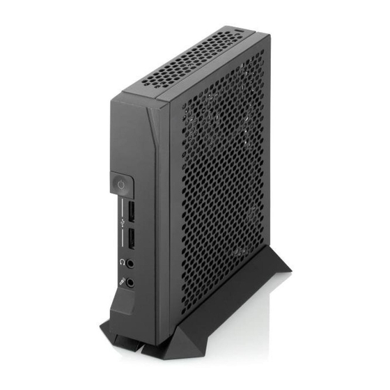
Page 17: Step 7 Adding Stands
Assembly Instructions SMARTCASE S500 Step 7 Adding Stands The desk stands included in the chassis kit can be used either for horizontal or vertical use. They can be fixed by plastic clips, in addition there are screws included for more secure stand assembly. - Page 18 Optionally, the stands can be secured by the screws. Horizontal Stand Position Vertical Stand Position Contact © 2018 Fujitsu Technology Solutions GmbH. Fujitsu, the Fujitsu logo are FUJITSU trademarks or registered trademarks of Fujitsu Limited in Japan and other Fujitsu Technology Solutions Gmbh countries.
Need help?
Do you have a question about the SMARTCASE S500 and is the answer not in the manual?
Questions and answers