Table of Contents
Advertisement
Quick Links
SWITCHER SYSTEM PACK
MFS-2000-C
MULTI FORMAT SWITCHER PROCESSOR
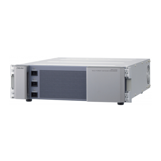
MFS-2000
1 M/E CONTROL PANEL
MKS-2010
1.5 M/E CONTROL PANEL
MKS-2015
1.5 M/E WIDE CONTROL PANEL
MKS-2017
MKS-2110M
MKS-2420M
BZS-2440M
BZS-2470M
OPERATION MANUAL
1st Edition (Revised 3)
MKS-2440
MKS-2470
HK-PSU02
HK-PSU11
[English]
BZS-2000M
Advertisement
Table of Contents

Related Manuals for Sony MFS-2000-C


Summary of Contents for Sony MFS-2000-C
- Page 1 SWITCHER SYSTEM PACK MFS-2000-C MULTI FORMAT SWITCHER PROCESSOR MFS-2000 1 M/E CONTROL PANEL MKS-2010 1.5 M/E CONTROL PANEL MKS-2015 1.5 M/E WIDE CONTROL PANEL MKS-2017 MKS-2110M MKS-2420M MKS-2440 MKS-2470 BZS-2000M BZS-2440M BZS-2470M HK-PSU02 HK-PSU11 OPERATION MANUAL [English] 1st Edition (Revised 3)
- Page 2 operated in a commercial environment. This equipment WARNING generates, uses, and can radiate radio frequency energy and, if not installed and used in accordance with the instruction To reduce the risk of fire or electric shock, manual, may cause harmful interference to radio do not expose this apparatus to rain or communications.
- Page 3 WARNING: THIS WARINING IS APPLICABLE FOR OTHER Für Kunden in Europa (nur MFS-2000, MKS-2010/2015/ COUNTRIES. 2017) 1. Use the approved Power Cord (3-core mains lead)/ Dieses Produkt besitzt die CE-Kennzeichnung und erfüllt die Appliance Connector/Plug with earthing-contacts that EMV-Richtlinie sowie die Niederspannungsrichtlinie der EG- conforms to the safely regulations of each country if Kommission.
- Page 4 Kundendienst- oder Garantiedokumenten aufgeführten Anschriften. Pour les clients en Europe Le fabricant de ce produit est Sony Corporation, 1-7-1 Konan, Minato-ku, Tokyo, Japon. Le représentant autorisé pour EMC et la sécurité des produits est Sony Deutschland GmbH, Hedelfinger Strasse 61, 70327 Stuttgart, Allemagne.
-
Page 5: Table Of Contents
Table of Contents Overview ................6 Features ..................6 Module Overview..............7 Location and Function of Parts .......... 8 MFS-2000 Front Panel ..............8 MFS-2000 Rear Panel ...............9 MKS-2010/2015/2017 Front Panel .........11 MKS-2010/2015/2017 Rear Panel ..........12 Example System Configuration ........14 MFS-2000 System Configuration ...........14 Exchanging Button Labels .......... -
Page 6: Overview
• MKS-2017 1.5 M/E Wide Control Panel: Overview 1.5 M/E wide, 592 mm width 20 cross point buttons Live broadcast functions The MFS-2000 Multi-Format Switcher Processor is a compact switcher supporting both HD and SD formats. It Redundant power supplies provides all functions essential for up-to-date video Redundant power supplies can be installed for both the production. -
Page 7: Module Overview
Large volume data storage Installation of this software gives the MKS-2440 the ability to handle both HD and SD formats. The MFS-2000 is equipped with a hard disk for storage of setting data and image data from switcher frame memory. BZS-2470M DME Upgrade Software Data can also be stored on “Memory Stick”... -
Page 8: Location And Function Of Parts
Note If a status indicator does not light when you turn a POWER switch on, there may be a fault in the power circuits. Turn the POWER switch off and contact your Sony service representative. Location and Function of Parts... -
Page 9: Mfs-2000 Rear Panel
The two connectors have a loop-through configuration. * For information about Ethernet switches that can be used in an MFS-2000 system, contact your Sony service representative. Signal input to one connector can be output from the other connector. If you will not be using the loop-through... - Page 10 Note e SWITCHER CTRL (Switcher Control) connector For information about installing an HK-PSU02, contact (RJ-45) your Sony service representative. Connect to an Ethernet switch. The MFS-2000 System is connected in the same way to the n FM DEVICE connector (IEEE1394)
-
Page 11: Mks-2010/2015/2017 Front Panel
If the status indicators do not light even though the AC when the status indicator is lit or flashing. power cord is connected, there may be failure in the unit. Disconnect the AC power cord and contact a Sony service Note or marketing representative. -
Page 12: Mks-2010/2015/2017 Rear Panel
Note An Ethernet switch is required to connect two or more DCU-8000 Device Control Units. Caution Contact a Sony service or marketing representative regarding installation of the HK-PSU11. b GPI (General Purpose Interface) connector (D-sub 25-pin) Connect to external devices for input and output of trigger signals. - Page 13 DEVICE connector (USB Type A) Connect devices with a USB interface, such as mice, keyboards, and pen tablets. Note Contact a Sony service or marketing representative for more information about devices which can be connected. Location and Function of Parts...
-
Page 14: Example System Configuration
Example System Configuration MFS-2000 System Configuration Ethernet switch Ethernet switch XGA compatible monitor MKS-2050/8050 Editing Keyboard Reference MFS-2000 Multi video signal Format Switcher Processor MKS-2010/2015/ 2017 Control Unit Output video signal Material video signal (Main line output/REC (camera/VTR etc.) VTR/Monitor etc.) Reference video signal BVE-9100 Editing Control System... -
Page 15: Exchanging Button Labels
Exchanging Button Adjusting Fader Torque Labels You can adjust faders without removing them from the center control panel or operation modules. A button top puller is supplied with the control panel. After changing a pattern assigned to a numeric button, you Proceed as follows to adjust faders. -
Page 16: Power Supply Unit Status Indicators
Exchange the Caution fault power unit Contact a Sony service or marketing representative before exchanging a power supply unit, or exchanging the fan unit Notes in the power supply unit. • When the unit is powered on, the status indicators may light momentarily in red and a whining sound may be heard. -
Page 17: Maintenance
Note on data read/write speed Data read/write speed may vary depending on the combination of the “Memory Stick” and “Memory Stick” compliant product you use. What is MagicGate? MagicGate is copyright protection technology developed by Sony Corporation. Maintenance / About “Memory Stick”... - Page 18 “Memory Stick” is set to LOCK. Memory Stick Duo”, “Memory Stick Micro”, “M2” and • Image data may be damaged in the following cases: are trademarks or registered trademarks of Sony - If you remove the “Memory Stick”, or turn the power Corporation.
-
Page 19: Specifications
Output Specifications Outputs 4 (BNC type), each with 2 outputs Signal format SMPTE292M/SMPTE259M-C Signal level 0.8 V p-p ±10% Signal transfer rate The following specifications show the reference 1.5 Gbps/270 Mbps performance for this unit and individual option boards/ units. Remote control connectors Design and specifications are subject to change without CTRL... -
Page 20: Mks-2010 1 M/E Control Panel
Accessories not supplied D-sub 25-pin, female TTL inputs: 8 AC power cord (for USA and Canada only) (125 V 10 A Relay contact outputs: 4 (30 V AC/DC, 2.4 m (8 ft)) (Part No.: 1-557-377-11) 0.1 A) AC power cord (for Europe only) (250 V 10 A 2.4 m Open collector outputs: 4 (8 ft)) (Part No.: 1-782-929-22) EDITOR PANEL... -
Page 21: Mks-2017 1.5 M/E Wide Control Panel
Storage temperature White switch cap (9) −20ºC to +60ºC (−4ºF to +140ºF) Mounting tool (1) Operating humidity Software Licence Agreement (1) 10% to 90% Dimensions (w/h/d) Accessories not supplied 440×102×446 mm (17 ×4 ×17 AC power cord (for USA and Canada only) (125 V 10 A inches) 2.4 m (8 ft)) (Part No.: 1-557-377-11) Mass... -
Page 22: Mks-2110M Input/Output Connector Board
PERIPH RJ-45 MKS-2110M Input/Output Connector Complies with 100Base-TX standard Board DEVICE USB Type A Maximum supply current 400 mA REMOTE BNC type, 75Ω General S-BUS Data transfer rate: 312/1250 Kbps Power requirements D-sub 25-pin, female 12 V DC TTL inputs: 8 Power consumption Relay contact outputs: 4 (30 V AC/DC, Max. -
Page 23: Mks-2440 Frame Memory Board Set
MKS-2440 Frame Memory Board Set HK-PSU11 Power Supply Unit Power requirements Operating temperature 12 V DC +5°C to +40°C (+41°F to +104°F) Power consumption Storage temperature Max. 100 W –20°C to +60°C (–4°F to +140°F) Dimensions (w/d) Operating humidity MY-112 board: 317×380 mm (12 ×15 10 % to 90 % (no moisture condensation) inches) - Page 24 Specifications...
- Page 25 The material contained in this manual consists of information that is the property of Sony Corporation and is intended solely for use by the purchasers of the equipment described in this manual. Sony Corporation expressly prohibits the duplication of any...
- Page 26 Sony Corporation MFS-2000-C Printed in Japan (SY) 2008.10.13 3-855-583-04 (1) © 2004...
Need help?
Do you have a question about the MFS-2000-C and is the answer not in the manual?
Questions and answers