Table of Contents
Advertisement
IDEAL INDUSTRIES, INC.
TECHNICAL MANUAL
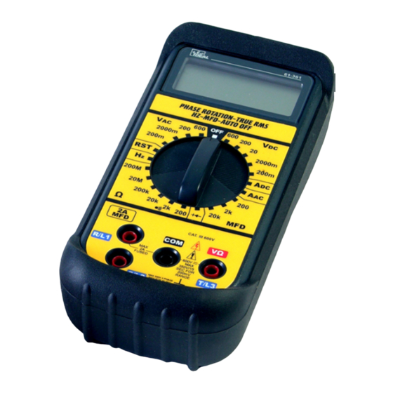
MODEL: 61-361
MODEL: 61-361 True RMS {Modified 2002}
The Service Information provides the following information:
• Precautions and safety information
• Specifications
• Performance test procedure
• Calibration and calibration adjustment procedure
• Basic maintenance (replacing the battery and fuses)
Form number: TM61361
Revision: 3. Date: Nov 2002
Form number TM61361
Rev 3 November 2002
Advertisement
Table of Contents

Subscribe to Our Youtube Channel
Related Manuals for IDEAL INDUSTRIES 61-361


Summary of Contents for IDEAL INDUSTRIES 61-361
- Page 1 IDEAL INDUSTRIES, INC. TECHNICAL MANUAL MODEL: 61-361 MODEL: 61-361 True RMS {Modified 2002} The Service Information provides the following information: • Precautions and safety information • Specifications • Performance test procedure • Calibration and calibration adjustment procedure • Basic maintenance (replacing the battery and fuses) Form number: TM61361 Revision: 3.
-
Page 2: Table Of Contents
General Specification 61-361 True RMS Voltage Specifications 61-361 True RMS Current Specifications 61-361 True RMS Resistance Specifications 61-361 True RMS Diode / Continuity Specifications 61-361 True RMS Capacitance Specifications 61-361 True RMS Phase Measurement 61-361 True RMS Performance Verification Table 1 Verification 61-361... -
Page 3: Introduction
The information provided in this document is for the use of qualified personnel only. Caution The 61-361 contains parts that can be damaged by static discharge. Follow the standard practices for handling static sensitive devices. For additional information about IDEAL INDUSTRIES, INC. and its products, and services, visit IDEAL INDUSTRIES, INC. -
Page 4: Specifications
Page 2 General specifications Model 61-361 and Model 61-361 True RMS {Modified} Characteristics Description Display 3 ½ Digit LCD display Display Count 2000 count, maximum reading 1999 Overrange Indication “OL” displayed Sampling Rate 3 time/second Operating Environment: 0°C to 50°C (32°F to 122°F) 70%RH... -
Page 5: General Specification 61-361 True Rms
DC. If the battery measures under 7.5V DC, replace the battery before beginning the performance test. 3. Input the values listed in Table 1 for the Standard 61-361 Input the values listed in Table 2 for the modified 61-361 True RMS units Form number TM61361... - Page 6 Page 4 Table 1 Performance Verification 61-361 Standard Function Setting /Range Input Low Limit High Limit ACV 200mV 190mV AC@ 50Hz 185.8 194.2 ACV 200mV 190mV AC@ 500Hz 185.8 194.2 ACV 200V 190V AC @ 50Hz 185.8 194.2 ACV 200V 190V AC @ 500Hz 185.8...
- Page 7 Page 5 Table 2 Performance Verification 61-361 True RMS Function Setting /Range Input Low Limit High Limit ACV 200mV 190mV AC@ 50Hz 185.8 194.2 ACV 200mV 190mV AC@ 500Hz 185.8 194.2 ACV 2000mV 1900mV @ 50Hz 1862 1938 ACV 2000mV...
-
Page 8: Calibration
6. Adjust VR2 (VR 200 ohm) until the display reads 190.0mV +/- 1 digit. Note : This is the only adjustment required for the 61-361. Calibration is complete. Battery Replacement (refer to Figure 1) 1. Disconnect the test leads from any circuit under test and turn off meter. -
Page 9: Replacing Fuses
Page 7 Replacing Fuse 1. Disconnect the test leads and turn the range switch to “OFF”. 2. Remove the three screws holding the bottom case cover 3 Use a digital multimeter in low resistance {ohms} mode to check the two fuses MFD input, 0.1A / 250V fast acting fuse.
Need help?
Do you have a question about the 61-361 and is the answer not in the manual?
Questions and answers
I have an older 61-361 meter and do not see any screws to allow for battery replacement. Am i missing them or is there something else that needs to be removed