Table of Contents
Advertisement
IDEAL INDUSTRIES, INC.
TECHNICAL MANUAL
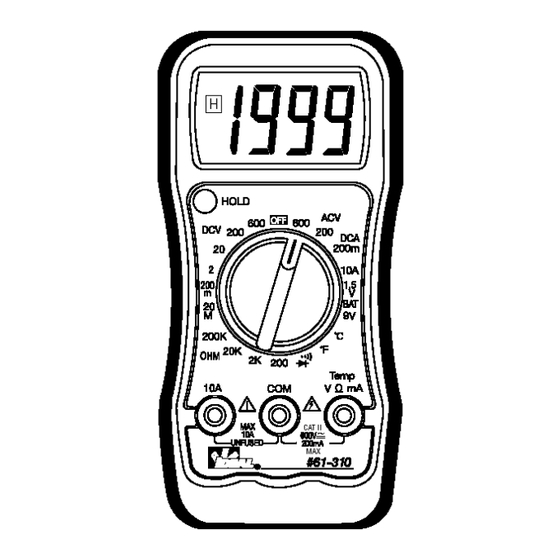
MODEL: 61-310
This Service Manual provides the following information:
Precautions and safety information
●
Specifications
●
Basic maintenance (cleaning, replacing the battery and fuses)
●
Performance test procedures
●
Calibration and calibration adjustment procedures
●
Form Number: TM61310
Revision: 2. Date: August 2007
Form Number TM61310
Visit us at www.TestEquipmentDepot.com
Back to the Ideal 61-310 Product Info Page
Rev 2 Aug 2007
99 Washington Street
Melrose, MA 02176
Phone 781-665-1400
Toll Free 1-800-517-8431
Advertisement
Table of Contents

Related Manuals for IDEAL INDUSTRIES 61-310


Summary of Contents for IDEAL INDUSTRIES 61-310
- Page 1 Calibration and calibration adjustment procedures ● 99 Washington Street Melrose, MA 02176 Phone 781-665-1400 Toll Free 1-800-517-8431 Visit us at www.TestEquipmentDepot.com Form Number: TM61310 Back to the Ideal 61-310 Product Info Page Revision: 2. Date: August 2007 Form Number TM61310 Rev 2 Aug 2007...
-
Page 2: Table Of Contents
TABLE OF CONTENTS Page Introduction Precautions and Safety Information Symbols Safety Specifications General Specifications Measurement Characteristics Voltage Specifications Current Specifications Resistance Specifications Diode Check, Continuity, Temperature Specifications Auto Power Off, Data Hold Function, Battery Test Physical and Environmental Characteristics Certifications and Compliances Required Equipment Basic Maintenance Opening the Meter Case... -
Page 3: Introduction
Caution The 61-310 series contain parts that can be damaged by static discharge. Follow the standard practices for handling static sensitive devices. For additional information about IDEAL INDUSTRIES, INC. and its products, and services, visit IDEAL INDUSTRIES, INC. -
Page 4: Safety
To avoid potential hazards, use the product only as specified. For operating instructions, see the 61-310 Digital Multimeter Instruction Manual. CAUTION: These statements identify conditions or practices that could result in damage to the equipment or other property. -
Page 5: Specifications
Page 3 SPECIFICATIONS specifications are warranted unless noted typical and apply to the 61-310. ted accuracies are at 23°C±5°C at less than 70% relative humidity and without the batte icator displayed. neral specifications Characteristics Description Display count 3 ½ digit liquid crystal display, 1999 count... -
Page 6: Measurement Characteristics
Page 4 asurement Characteristics curacy is ±(% reading + number of digits) at 23°C ± 5°C, less than 80% R.H. DC Volts Over voltage Range Resolution Accuracy protection 200.0mV 100μV 2.000V 0.5% + 2 20.00V 10mV 600V rms 200.0V 100mV 600V 0.8% + 2 ut Impedance: 10MΩ... -
Page 7: Resistance Specifications
Page 5 (4) Resistance Over voltage Range Resolution Accuracy protection 200.0Ω * 0.1Ω 0.8% + 4 2.000KΩ 1Ω 20.00KΩ 10Ω 0.8% + 2 250V rms 200.0KΩ 100Ω 2.000MΩ 1KΩ 20.00MΩ * 10KΩ 3.0% + 3 en circuit Voltage: -1.5V approx. <... -
Page 8: Physical And Environmental Characteristics
Page 6 Physical and Environmental Characteristics Characteristics Description 150mm(H) ×76mm (W) ×38mm(D) (with holster) Dimensions (H×W×D) 5.9” (H) x 3.0”(W) x1.5”(D) Weight (with battery& holster) 0.219Kg (7.1 oz.) Environmental characteristics Description Temperature operating range 0 to +40°C Non-Operating -20 to +60°C <80% R.H. Humidity (operating) <75% R.H. -
Page 9: Required Equipment
Page 7 quired Equipment Required equipm ent is listed in Tab le B. If the recommended models are not available, equipment with equivalent specifications may be used. Repa irs or servicing should be performed only b y qualified personnel. Table B. -
Page 10: Basic Maintenance
3. For Fuse repla cement follow instructions in the Fus e Replacement section. Replacing the Battery The 61-310 meter is po wered by a 9V battery, type s are, NEDA 1604, JIS006P, IEC 6F22 1. Remove the ru bber holster. -
Page 11: Replacing Fuses
F-310 Fuse: 250mA 250V FAST BLOW Fuse se Replacement The 61-310 replacement fuse is part number: F-310 Fuse Rating is: 250mA 250V FAST BLOW 1. Remove the rubber holster. 2. Remove the two screws on the battery cover and open the battery cover. -
Page 12: Performance Tests
Page 10 Perf ormance Tests The following performance test s verify the complete operability of the meter and check the uracy of each meter function against the meter’s specifications. uracy specifications are valid for a period of one year after calibration, when measured at an operating temperature of 18°C to 28°C and a maximum of 80% relative humidity. -
Page 13: Testing The Dc Current Function
Page 11 Table 2: AC Voltag e Test: Range Step Input Frequency Reading 200V 2.0V 60Hz 1.0 to 3.0 200V 2.0V 400Hz 1.0 to 3.0 200V 190.0V 60Hz 186.7 to 193.3 200V 190.0V 400Hz 186.7 to 193.3 600V 600V 60Hz 583.0 to 617.0 600V 600V... -
Page 14: Testing The Diode And Continuity Functions
Page 12 Table 4: Ω Resistance Test: Range Step Source Reading *200 OHM 2.0Ω 1.6 to 2.4 *200 OHM 190.0Ω 188.3 to 191.7 2K OHM 1.900K Ω 883 to 1 .917 20K OHM 19.00K Ω 18.83 to 19.17 200K OHM 190.0K Ω... -
Page 15: Calibration
Page 13 Cali bration Procedure To Recalibrate your meter: It is recommended that the Multimeter be ca librated once ea ch year. 1. Perform calibration at an a mbient tempe rature of 23°C±2°C and a relative humidity of <70% Dis nect the te st lead s and turn th...
Need help?
Do you have a question about the 61-310 and is the answer not in the manual?
Questions and answers