Table of Contents
Advertisement
99 Washington Street
Melrose, MA 02176
Phone 781-665-1400
Toll Free 1-800-517-8431
Visit us at www.TestEquipmentDepot.com
IDEAL INDUSTRIES, INC. TECHNICAL
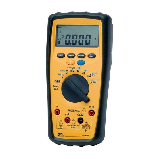
MODEL: 61-484
MODEL: 61-486
Multimeters Service Information
The Service Information provides the following information:
●
Precautions and safety information
●
Specifications
●
Basic maintenance (cleaning, replacing the battery and fuses)
●
Performance test procedures
●
Calibration and calibration adjustment procedures
Form number: TM61480II
Revision:1. Date: July 2011
Form number TM61480II
Rev 1 July 2011
Advertisement
Table of Contents

Subscribe to Our Youtube Channel
Related Manuals for IDEAL INDUSTRIES 61-484


Summary of Contents for IDEAL INDUSTRIES 61-484
- Page 1 99 Washington Street Melrose, MA 02176 Phone 781-665-1400 Toll Free 1-800-517-8431 Visit us at www.TestEquipmentDepot.com IDEAL INDUSTRIES, INC. TECHNICAL MODEL: 61-484 MODEL: 61-486 Multimeters Service Information The Service Information provides the following information: ● Precautions and safety information ● Specifications ●...
-
Page 2: Table Of Contents
Table of Contents Introduction ..............................1 Precautions and Safety Information........................1 The Symbols ..............................1 SAFETY ................................2 SPECIFICATIONS ..............................3 General specifications ........................... 3 Measurement Characteristics ........................3 Physical and Environmental Characteristics ....................10 Certifications and compliances ........................10 Required Equipment ............................ -
Page 3: Introduction
The information provided in this document is for the use of qualified personnel only. Caution The 61-484/61-486 contains parts that can be damaged by static discharge. Follow the standard practices for handling static sensitive devices. Precautions and Safety Information Use the Meter only as described in the Service Manual. -
Page 4: Safety
SAFETY Review the following safety precautions to avoid injury and prevent damage to this product or products connected to it. To avoid potential hazards, use the product only as specified. CAUTION: These statements identify conditions or practices that could result in damage to the equipment or other property. -
Page 5: Specifications
SPECIFICATIONS All specifications are warranted unless noted typical and apply to the 61-484/61-486. Stated accuracies are at 23°C±5°C at than 80% relative humidity and without the battery indicator displayed. General specifications Characteristics Description Display count 6000 Analog Bar Graph segment, negative indicated positive implied... - Page 6 ±(0.08% reading + 2 digits) ±(0.09% reading + 2 digits) 1000V Input Impedance: 10MΩ Overload Protection: AC/DC 1000V. (2) AC Voltage Range Resolution 61-486 Accuracy (Sine Wave) 61-484 Accuracy (Sine Wave) 6.000V 0.001V 60.00V 0.01V 600.0V 0.1V ±(0.8% reading + 3 digits) ±(1.0% reading + 3 digits)
- Page 7 ±(0.08% reading + 2 digits) ±(0.1% reading + 2 digits) Input Impedance: 10MΩ Overload Protection: AC/DC 1000V. (5) AC mV Range Resolution 61-486 Accuracy (Sine Wave) 61-484 Accuracy (Sine Wave) 60.00mV 0.01mV ±(1.2% reading + 5 digits) 600.0mV 0.1mV ±(1.2% reading + 5 digits) ±(1.5% reading + 5 digits)
- Page 8 Maximum measurement time: 3 minutes at 10A with at least 20 minutes rest time. Overload Protection: AC/DC 11A. (9) AC Current Range Resolution 61-486 Accuracy (Sine Wave) 61-484 Accuracy (Sine Wave) 6.000A* 0.001A ±(1.2% reading + 3 digits) ±(1.5% reading + 3 digits) 10.00A...
- Page 9 (12) AC mA Range Resolution 61-486 Accuracy (Sine Wave) 61-484 Accuracy (Sine Wave) 60.00mA 0.01mA ±(1.2% reading + 3 digits) ±(1.5% reading + 3 digits) 600.0mA 0.1mA Frequency Response: 50 ~ 1kHz (Sine Wave) AC Conversion Type: RMS sensing, RMS indication Additional Accuracy by Crest Factor (C.F.): Same as ACV.
- Page 10 Open Circuit Voltage: Approx. 2.5V Continuity: Built-in buzzer sounds when measured resistance is less than 30Ω and sounds off when measured resistance is more than 100Ω, Between 30Ω to 100Ω the buzzer maybe sound or off either. Continuity Indicator: 2.7KHz Tone Buzzer Response Time of Buzzer: < 500 μsec. Overload Protection: AC/DC 1000V.
- Page 11 (19) Temperature (61-486 Only) Range Resolution Accuracy ±(1% reading + 10 digits) -40.0℃ ~ 400.0℃ 0.1℃ ±(1% reading + 18 digits) -40.0℉ ~ 752.0℉ 0.1℉ Does not include accuracy of the thermocouple probe. Accuracy specification assumes surrounding temperature stable to ±1 ℃. For surrounding ...
-
Page 12: Physical And Environmental Characteristics
(30) Operating Temperature -10℃ ~ 30℃, ≦80%RH 30℃ ~ 40℃, ≦75%RH 40℃ ~ 50℃, ≦45%RH (31) Storage Temperature -20℃ ~ +60℃, 0 ~ 80%RH (No batteries) Physical and Environmental Characteristics Characteristics Description Dimensions (H×W×D) 48mm×94mm×190mm (with holster) Weight (with battery) 460g (with battery) Environmental characteristics... -
Page 13: Required Equipment
Meets the intent of Directive 2004/108/EEC for Electromagnetic Compatibility and Low Voltage Directive 2006/95/EEC for specifications as listed in the official Journal of the European EC Declaration of Conformity Communities: EN 61326 IEC/EN 61010 Required Equipment Required equipment is listed in Table B. If the recommended models are not available, equipment with equivalent specifications may be used. -
Page 14: Basic Maintenance
Basic Maintenance Warning To avoid shock, remove the test leads and any input signals before opening the case or replacing the battery. Opening the Meter Case Caution To avoid unintentional shock circuit, always place the uncovered Meter assembly on a protective surface. When the case of the Meter is open, circuit connections are exposed. -
Page 15: Testing Fuses
Testing Fuses To test the internal fuses of the meter. 1. Turn the rotary switch to the Ω position. 2. To test FUSE 71 (Bussmann DMM-B-11A recommended), plug a test lead into VΩHz input terminal, and use the probe to touch the A input terminal. The display should indicate between 0.0 to 0.3Ω. 3. -
Page 16: Performance Tests
Performance Tests The following performance tests verify the complete operability of the Meter and check the accuracy of each Meter function against the Meter’s specifications. Accuracy specifications are valid for a period of one year after calibration, when measured at an operating temperature of 18°C to 28°C and a maximum of 80% relative humidity. -
Page 17: Testing The Resistance Function
Step Input Frequency Reading 49.35mV ~ 50.65mV 50.00mV AC 1000Hz 493.5mV ~ 506.5mV 500.0mV AC 50Hz 493.5mV ~ 506.5mV 500.0mV AC 1000Hz 49.86mV ~ 50.14mV 50.00mV DC 499.4mV ~ 500.6mV 500.0mV DC Testing the Resistance Function To verify accuracy in the resistance function, do the following: 1. -
Page 18: Testing The Diode Function
Table 3 Capacitance Test: Step Input Reading 0.887µF ~ 0.913µF 0.900µF 8.87µF ~ 9.13µF 9.00µF 88.7µF ~ 91.3µF 90.0µF 0.887mF ~ 0.913mF 0.900mF 8.87mF ~ 9.13mF 9.00mF Testing the Diode Function To verify accuracy in the AC and DC capacitance function, do the following: 1. - Page 19 Table 5 mA Test: Step Input Frequency Reading 49.37mA ~ 50.63mA 50.00mA AC 50Hz 49.37mA ~ 50.63mA 50.00mA AC 1000Hz 493.7mA ~ 506.3mA 500.0mA AC 50Hz 493.7mA ~ 506.3mA 500.0mA AC 1000Hz 49.57mA ~ 50.43mA 50.00mA DC 495.7mA ~ 504.3mA 500.0mA DC Testing the Ampere Function To verify accuracy in the AC and DC ampere ranges, do the following:...
- Page 20 Table 7 Temperature Test: Step Input Reading -37.8°F ~ -42.2°F -40.0°F -1.8°F ~ 1.8°F 0.0°F 29.9°F ~ 34.1°F 32.0°F 344.7°F ~ 355.3°F 350.0°F 691.2°F ~708.8°F 700.0°F Page 18...
-
Page 21: Calibration
Deactivate Calibration Procedure Mode Turn the meter off to deactivate calibration procedure mode. Set Meter Model mode (61-484 and 61-486 61-486 / 61-484) After Activate Calibration Procedure Mode, Press the “Min Max” button to select the meter model. Standard Function Calibration (Voltage, Ampere, Resistance, Diode, Capacitance) ... -
Page 22: Calibration Adjustment Point
Calibration Adjustment Point AC and DC Volts Table Function Range Standard Value 61-486 61-484 DC mV 60.00mV 30.00mV 55.00mV 600.0mV 300.0mV 550.0mV 6.000V 3.000V 5.500V 60.00V 30.00V 55.00V 600.0V 300.0V 550.0V 1000V 950V AC mV 60.00mV 2.00mV, 50Hz 10.00mV, 50Hz 55.00mV, 50Hz... -
Page 23: Resistance, Capacitance, Diode, Ac & Dc Current, Temperature Table
Resistance, Capacitance, Diode, AC & DC Current, Temperature Table Function Range Standard Value 61-486 61-484 Resistor 600.0Ω 500.0Ω 6.000kΩ 5.000kΩ 60.00kΩ 50.00kΩ 600.0kΩ 500.0kΩ 6.000MΩ 5.000MΩ 40.00MΩ 38.00MΩ Capacitor 1.000μF 0.370μF 10.00μF 3.70μF 100.0μF 37.0μF 1.000mF 0.360mF 10.00mF 3.60mF Diode 2.000V...
Need help?
Do you have a question about the 61-484 and is the answer not in the manual?
Questions and answers