Table of Contents
Advertisement
IDEAL INDUSTRIES, INC.
TECHNICAL MANUAL
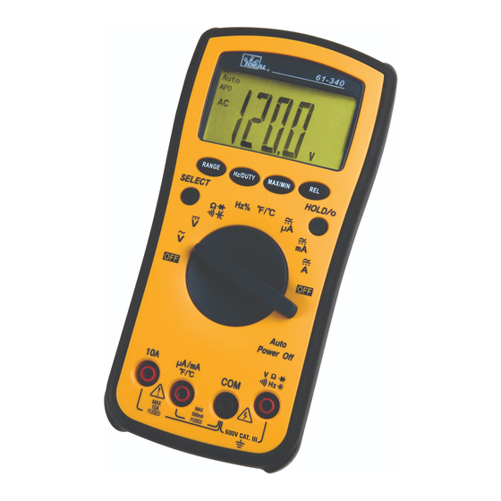
MODEL: 61-340
MODEL: 61-342
Multimeter Service Information
The Service Information provides the following information:
• Precautions and safety information
• Specifications
• Basic maintenance (cleaning, replacing the battery and fuses)
• Performance test procedures
• Calibration and calibration adjustment procedures
Form Number: TM61340-2
Revision: 2. Date: November 2007
Form Number
TM61340-2
Rev
2
November 2007
Advertisement
Table of Contents

Subscribe to Our Youtube Channel
Related Manuals for IDEAL INDUSTRIES 61-340


Summary of Contents for IDEAL INDUSTRIES 61-340
- Page 1 IDEAL INDUSTRIES, INC. TECHNICAL MANUAL MODEL: 61-340 MODEL: 61-342 Multimeter Service Information The Service Information provides the following information: • Precautions and safety information • Specifications • Basic maintenance (cleaning, replacing the battery and fuses) • Performance test procedures • Calibration and calibration adjustment procedures Form Number: TM61340-2 Revision: 2.
-
Page 2: Table Of Contents
TABLE OF CONTENTS Page Introduction Precautions and Safety Information Symbols Safety Specifications General Specifications Measurement Characteristics Voltage Specifications Current Specifications Resistance, Diode, Continuity, Capacitance Specifications Frequency, Temperature Specifications Auto Power Off, Data Hold/Backlight, SELECT, RANGE, REL, Hz/DUTY, MAX/MIN Physical and Environment Characteristics Certifications and Compliances Required Equipment Basic Maintenance... -
Page 3: Introduction
The 61-340 serials contain parts that can be damaged by static discharge. Follow the standard practices for handling static sensitive devices. For additional information about IDEAL INDUSTRIES, INC. and its products, and services, visit IDEAL INDUSTRIES, INC. web site at: www.idealindustries.com... -
Page 4: Safety
Review the following safety precautions to avoid injury and prevent damage to this product or any products connected to it. To avoid potential hazards, use the product only as specified. For operating instructions, see the 61-340 / 61-342 Digital Multimeter Instruction Manual. CAUTION: These statements identify conditions or practices that could result in damage to the equipment or other property. -
Page 5: Specifications
Page 3 SPECIFICATIONS All specifications are warranted unless noted typical and apply to the 61-340 & 61-342 Stated accuracies are at 23°C±5°C at less than 75% relative humidity and without the battery indicator displayed. General specifications Characteristics Description Display count... -
Page 6: Measurement Characteristics
100mV 750V ±(1.2%+5) Input Impedance: 10MΩ AC Conversion Type: 61-340: Average sensing rms indication calibrated to the sine wave input. 61-342: AC conversion is True RMS responding, calibrated to a sinusoidal waveform Crest Factor: C.F. = Peak/RMS For non-sinusoidal waveform, C.F. > 2 add ±1% to accuracy, Frequency response: 40~400Hz... - Page 7 Blow Fuse ±(2.0% reading + 5 digits) * 40.00mA 10μA 40Hz 400Hz 400.0mA 0.1mA Overload Protection: μA / mA Input: 500mA,250V Fast Blow fuse. (61-340 / 61-342) (4b) AC Current (61-340 / 61-342) Range Resolution Accuracy Input Protection 4.000A 0.001mA ±(2.5% reading + 5 digits) *...
-
Page 8: Resistance, Diode, Continuity, Capacitance Specifications
40.00MΩ * 10KΩ ±(2.0% reading + 5 digits) Open circuit Voltage: 0.44V approx. < 5 digit of reading rolling. < 2% of reading rolling. (6) Diode Check and Continuity (for 61-340 / 61-342) Max. Test Max. Open Range Resolution Accuracy... -
Page 9: Frequency, Temperature Specifications
10.00KHz 10Hz 600V rms (± 0.1% + 3 digit) 100.0KHz 100Hz 1.000MHz 10KHz 4.000MHz 10KHz 3.0V rms (9) Temperature: Type K thermocouple (for 61-340 / 61-342) Overload Range Resolution Accuracy protection º º º ±3.0% ± 3 -50 to 750 Not Specified º... - Page 10 Page 8 (14) REL Press this button the meter enter relative measuring state and “Δ” symbol appear on LCD. The result of the relative measurement is the difference between measuring value and reference value. The reference value is produced same as momentary reading value when pressing this button, press it again to exit this state and “Δ”...
-
Page 11: Physical And Environment Characteristics
Page 9 Physical and Environmental Characteristics Characteristics Description 180mm(H) ×91mm (W) ×43mm(D) (with holster) Dimensions (H×W×D) 7.1” (H) x 3.6”(W) x1.7”(D) Weight (with battery& holster) 0.379Kg (13.4 oz.) Environmental characteristics Description Temperature operating 0 to +40°C Non-Operating -20 to +60°C <75% R.H. Humidity (operating) <70% R.H. -
Page 12: Required Equipment
Page 10 Required Equipment Required equipment is listed in Table B. If the recommended models are not available, equipment with equivalent specifications may be used. Repairs or servicing should be performed only by qualified personnel. Table B. Required Equipment Equipment Required Characteristics Recommended Model AC Voltage Range: 0... -
Page 13: Basic Maintenance
3. For fuse replacement, follow instructions under Fuse Replacement section. Replacing the Battery The 61-340/61-342 meter are both powered by 9V, types are, NEDA 1604, JIS006P, IEC 6F22 1. Remove the rubber holster 2. Remove the screw on the battery cover and open the battery cover 3. -
Page 14: Replacing Fuses
Fuse Replacement The 61-340 and 61-342 are fused in both the μA /mA input and 10 amperes input ports. μA /mA input port is fused by a F340: 500mA, 250V FAST BLOW fuse, 10 A input port is fused by F342: 10A, 250V FAST BLOW fuse 1. -
Page 15: Performance Tests
The following performance tests verify the complete operability of the meter and check the accuracy of each meter function against the meter’s specifications. For operating instructions, see the 61-340 / 61-342 Digital Multimeter Instruction Manual. Accuracy specifications are valid for a period of one year after calibration, when measured at an operating temperature of 18°C to 28°C and a maximum of 75% relative humidity. -
Page 16: Testing The Voltage Function
Page 14 Testing the Voltage Function (for 61-340 / 61-342) To verify accuracy in the AC and DC voltage ranges, do the following: 1. Turn the rotary switch to “ ” position. 2. Connect the calibrator to the and COM inputs on the meter. -
Page 17: Testing The Dc Current Functions
297.4 to 302.6 4000µA 3000µA 2974 to 3026 Testing the DC milli amperes Function (for 61-340 and 61-342) 1. Connect the calibrator to the and COM inputs on the meter. 2. Turn the rotary switch to a. Press the SEL button to select the DC function 3. -
Page 18: Testing The Ac Current Functions
400mA 300.0mA 297.3 to 302.7 Testing the DC ampere Function (for 61-340 and 61-342) 1. Connect the calibrator to the 10A and COM inputs on the meter. 2. Turn the rotary switch to a. Press the SELECT button to select the DC function 3. - Page 19 300.0mA 400Hz 293.5 to 306.5 Testing the AC A function (for 61-340 / 61-342) 1. Connect the calibrator to the 10A and COM inputs on the meter. 2. Turn the rotary switch to a. Press the SELECT button to select the AC function b.
-
Page 20: Testing The Resistance Function
Page 18 Testing the Resistance Function (for 61-340 / 61-342) To verify the accuracy of the resistance function, do the following: 1. Connect the calibrator to and COM on the meter. 2. Turn the rotary switch to a. Press the SELECT button to select the Ω function 3. - Page 21 79.5 to 120.5 1000µF 1000µF 795 to 1205 Checking the Diode Test Function (for 61-340 / 61-342) To check the diode test function, do the following: 1. Connect the DVM (Digital Voltage Meter) to the and COM inputs on the meter.
-
Page 22: Testing The Frequency Function
1MHz 3V rms 900kHZ 898.7to 901.3 Testing the Duty Cycle Function (for 61-340 / 61-342) To verify the accuracy of the meter’s frequency function, do the following: 1. Connect the calibrator to the and COM inputs on the meter. 2. Note: The accuracy of the calibrator’s frequency function must be appropriate for the specified accuracy of the meter. -
Page 23: Testing The Temperature Function
Page 21 Testing the Temperature Function (for 61-340 / 61-342) To verify the accuracy of the meter’s temperature function, do the following: 1. Connect the calibrator to the and COM inputs on the meter. º º 2. Set the rotary switch to the C as instructed in Table 8. -
Page 24: Calibration
3. Using a small flat-tipped screwdriver, adjust VR1 until the display reads 299.5 to 300.5mV 4. Disconnect the DC calibrator from the meter. (B) AC V Calibration (Adjust VR2) Model 61-340: 1. Set the rotary switch to position. “ ” for the AC Volts function. - Page 25 Page 23 6. Using a small flat-tipped screwdriver, adjust VRtr until the display reads 2.995 to 3.005Volts 7. Disconnect the AC calibrator from the meter. (C) TEMP Calibration (Adjust VR3) º 1. Set the rotary switch to the " F/ ºC " position. 2.
Need help?
Do you have a question about the 61-340 and is the answer not in the manual?
Questions and answers