Table of Contents
Advertisement
IDEAL INDUSTRIES, INC.
TECHNICAL MANUAL
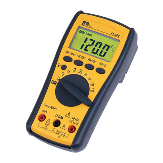
MODEL: 61-320
MODEL: 61-322
MODEL: 61-324
The Service Information provides the following information:
• Precautions and safety information
• Specifications
• Performance test procedure
• Calibration and calibration adjustment procedure
• Basic maintenance (cleaning, replacing the battery and fuses)
Form Number: TM61320-2-4
Revision: 2. Date: Sep 2002
Form number TM61320-2-4
Rev 2 September 2002
Advertisement
Table of Contents

Subscribe to Our Youtube Channel
Related Manuals for IDEAL INDUSTRIES 61-320


Summary of Contents for IDEAL INDUSTRIES 61-320
- Page 1 IDEAL INDUSTRIES, INC. TECHNICAL MANUAL MODEL: 61-320 MODEL: 61-322 MODEL: 61-324 The Service Information provides the following information: • Precautions and safety information • Specifications • Performance test procedure • Calibration and calibration adjustment procedure • Basic maintenance (cleaning, replacing the battery and fuses) Form Number: TM61320-2-4 Revision: 2.
-
Page 2: Table Of Contents
TABLE OF CONTENTS Page # Introduction Precautions and Safety Information Symbols Safety Specifications General Specification Voltage Specifications Current Specifications Resistance, Diode, Continuity Specifications Capacitance, Frequency Specifications Physical and environment characteristics Certification and compliance Required Equipment Basic Maintenance Opening the Meter Case Replacing the Battery Testing Fuses Replacing Fuses... -
Page 3: Introduction
The information provided in this document is for the use of qualified personnel only. Caution The 61-320, 61-322, and 61-324 contain parts that can be damaged by static discharge. Follow the standard practices for handling static sensitive devices. For additional information about IDEAL INDUSTRIES, INC. and its products, and services, visit IDEAL INDUSTRIES, INC. -
Page 4: Safety
Page 2 SAFETY Review the following safety precautions to avoid injury and prevent damage to this product or any products connected to it. To avoid potential hazards, use the product only as specified. CAUTION. These statements identify conditions or practices that could result in damage to the equipment or other property. -
Page 5: Specifications
Page 3 SPECIFICATIONS All specifications are warranted unless noted typical and apply to the 61-320, 61-322 and 61-324. Stated accuracies are at 23ºC ± 5ºC at less than 80% relative humidity and without the battery indicator displayed. General specifications Characteristics... -
Page 6: Voltage Specifications
: CMRR > 100dB at DC, 50Hz / 60Hz NMRR > 50dB at DC, 50Hz / 60Hz AC Conversion Type: 61-320: Average sensing rms indication. 61-322 / 61-324: AC conversions are ac-coupled, true rms responding, calibrated to the sine wave input. -
Page 7: Current Specifications
Page 5 DC Current Over voltage Range Resolution Accuracy protection 600.0µA 6000µA 600V rms1A (600) Fast ±(1.0%+2 dgt) blow fuse 60.00mA 10mV 600.0mA 100mV AC Current Over voltage Range Resolution Accuracy protection 600.0µA 600V rms 6000µA ±(1.5%+2 dgt) 1A (600) Fast blow 50Hz ~ 500Hz * 60.00mA 10mV... -
Page 8: Capacitance, Frequency Specifications
Page 6 Frequency Overload Range Sensitivity Accuracy protection 6000Hz 100mV rms * 60.00KHz Frequency : 600V rms 600.0KHz 0.01%±1digit 6.000MHz 250mV rms 60.00MHz 1V rms * Less than 20Hz, the sensitivity is 1.5V rms. Capacitance Overload Range Accuracy protection 6.000nF 60.00nF 600.0nF ±(1.9% + 8 dgt) -
Page 9: Physical And Environment Characteristics
Page 7 Physical and Environmental Characteristics Characteristics Description 158mm x 76mm x 38mm Dimensions (H x W x D) 164mm x 82mm x 44mm (with holster) Weight (with battery) 0.3Kg With holster 0.5Kg Environmental Characteristics Description Temperature operating 0 to + 50ºC Non-Operating -20 to + 60ºC Humidity (operating) -
Page 10: Required Equipment
Page 8 Required Equipment Required equipment is listed in Table B. If the recommended models are not available, equipment with equivalent specifications may be used. Repairs or servicing should be performed only by qualified personnel. Table B. Required Equipment Equipment Required Characteristics Recommended Model Calibrator... -
Page 11: Basic Maintenance
Using a screwdriver, remove the four screws. Replacing the Battery The meter is powered by 1.5V x 2 batteries for 61-320 and a single 9V battery for 61-322 and 61-324. To replace the battery, refer to Figure 1A. Figure 1A... -
Page 12: Testing Fuses
Page 10 Testing Fuses To test the internal fuses of the meter: 1. Turn the rotary selector switch to the Ω position. 2. To test FS1, plug a test lead into VΩHz input terminal and touch the probe to the mA input terminal. The display should indicate between 0.0 to 0.2 Ω. -
Page 13: Performance Tests
Page 11 Performance Tests The following performance tests verify the complete operability of the meter and check the accuracy of each meter function against the meter’s specifications. Accuracy specifications are valid for a period of one year after calibration, when measured at an operating temperature of 18ºC to 28ºC and at a maximum of 80% relative humidity. -
Page 14: Testing The Resistance Function
Page 12 Table 1 AC Voltage Test: Step Input Frequency Reading 5.800V 50Hz 5.743 to 5.857 5.800V 500Hz 5.743 to 5.857 58.00V 50Hz 57.43 to 58.57 58.00V 500Hz 57.43 to 58.57 580.0V 50Hz 574.3 to 585.7 580.0V 500Hz 574.3 to 585.7 750V 50Hz 738 to 762... -
Page 15: Testing The Capacitance Function
Page 13 Testing the Capacitance Function The meter measures capacitance by charging the capacitor with a known direct current, measuring the resultant voltage, and calculating the capacitance. If the same capacitance is measured on an impedance bridge, a different reading may result. This variance is likely to be greater at higher frequencies. To verify the accuracy of the capacitance measuring function, do the following: 1. -
Page 16: Testing The Microamp Function
Page 14 Table 5 AC mA Test: Step Source Frequency Reading 58.00mA 50Hz 56.93 to 59.07 58.00mA 500Hz 56.93 to 59.07 580.0mA 50Hz 569.3 to 590.7 580.0mA 500Hz 569.3 to 590.7 6. Turn the rotary switch to mA . 7. Apply the inputs for steps 1-2 in Table 6. 8. -
Page 17: Calibration
Perform calibration at an ambient temperature of 23ºC ±2ºC and relative humidity of 75% or less Calibration for the Model 61-320, 61-322 and 61-324: 1. Disconnect the test leads and turn the meter off. Remove the test leads from the front terminals. -
Page 18: Form Number Tm61320-2-4 Rev 2 September
Page 16 Figure 3 - Calibration Adjustment Points Form number TM61320-2-4 Rev 2 September 2002... - Page 19 Page 17 Form number TM61320-2-4 Rev 2 September 2002...
Need help?
Do you have a question about the 61-320 and is the answer not in the manual?
Questions and answers