Table of Contents
Advertisement
IDEAL INDUSTRIES INC.
TECHNICAL MANUAL
MODELS:
61-633
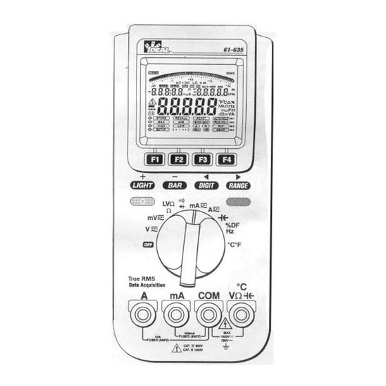
61-635
The Service Information provides the following information:
• Precautions and safety information
• Specifications
• Basic maintenance (cleaning, replacing the battery and fuses)
• Performance test procedures
• Calibration and calibration adjustment procedures
Form Number: TM61633-5
Revision: 5. Date: December 2006
Form Number TM61633-5
Rev 5 Dec 2006
Advertisement
Table of Contents

Subscribe to Our Youtube Channel
Related Manuals for IDEAL INDUSTRIES 61-635


Summary of Contents for IDEAL INDUSTRIES 61-635
- Page 1 IDEAL INDUSTRIES INC. TECHNICAL MANUAL MODELS: 61-633 61-635 The Service Information provides the following information: • Precautions and safety information • Specifications • Basic maintenance (cleaning, replacing the battery and fuses) • Performance test procedures • Calibration and calibration adjustment procedures Form Number: TM61633-5 Revision: 5.
-
Page 2: Table Of Contents
TABLE OF CONTENTS Title Page Introduction Precautions and Safety Information Symbols Safety Information Specifications General Specification Voltage Specifications dBm / dB Specifications Current Specifications Peak Hold, Resistance Specifications Continuity and Diode Specifications Capacitance Specifications Frequency Counter and Duty Factor Specifications Temperature Specifications Physical and environment characteristics Certification and compliance... -
Page 3: Introduction
Caution The 61-630 serials contain parts that can be damaged by static discharge. Follow the standard practices for handling static sensitive devices. For additional information about IDEAL INDUSTRIES and its products, and services, visit IDEAL INDUSTRIES web site at: www.idealindustries.com Precautions and Safety Information Use the Meter only as described in the Users Manual. -
Page 4: Safety Information
Page 2 SAFETY Review the following safety precautions to avoid injury and prevent damage to this product or any products connected to it. To avoid potential hazards, use the product only as specified. CAUTION. These statements identify conditions or practices that could result in damage to the equipment or other property. WARNING. -
Page 5: Specifications
Page 3 SPECIFICATIONS All specifications are warranted unless noted typical and apply to models 61-633 and 61-635. ° Stated accuracies are at 23 ±5°C at less than 80% relative humidity and without the battery indicator displayed. General specifications Description Characteristics LCD display digits 4¾... -
Page 6: Voltage Specifications
Measurement Characteristics All at 23°C ±5°C, < 80% Rh. Specifications are expressed as ±([% of reading] + [number of digits]). Multiply accuracy Digits by l0 in 40,000 count Mode. DC VOLTAGE: 61-633 61-635 40mV ± (0.20%+8d) ± (0.06% + 8d) 400mV ±... -
Page 7: Current Specifications
Page 5 DC CURRENT: 61-633 61-635 40mA, 400mA, 4A, 10A ± (0.50% + 4d) ±(0.20% + 4d) AC CURRENT: 61-633 61-635 40mA, 400mA, 4A, 10A ±(1.20% + 8d) ± (0.80% + 8d) Bandwidth 40Hz ~ 400Hz 40Hz ~ 400Hz 40mA, 400mA, 4A, 10A Range: 1µA in the 40mA range... -
Page 8: Capacitance Specifications
Page 6 CAPACITANCE Capacitance 61-633 61-635 4nF, 40nF ± (1 .90% + 20d) ± (0.90% + 20d) 400nF, 4µF 40µF, 400µF ± (2.90% + 20d) ± (1 .90% + 20d) 4mF, 10mF ± (3.90% + 20d) ± (2.90% + 20d) Note: For best measurements, use REL mode in the nF ranges. -
Page 9: Certification And Compliance
Page 7 Certifications and compliances Safety Designed to IEC 1010-1, UL3111-1 and CSA specifications 1000V DC Category II 600V DC Category III Input rating 750V AC Category II 600V AC Category III CAT III: Distribution level mains, fixed installation. CAT II: Local level mains, appliances, portable equipment. Over voltage category CAT I: Signal level, special equipment or parts of equipment, telecommunication, electronics. -
Page 10: Required Equipment
Page 8 Required Equipment Required equipment is listed in Table B. If the recommended models are not available, equipment with equivalent specifications may be used. Repairs or servicing should be performed only by qualified personnel. Table B. Required Equipment Recommended Equipment Required Characteristics Model... -
Page 11: Basic Maintenance
Page 9 Basic Maintenance Warning To avoid shock, remove the test leads and any input signals before opening the case or replacing the battery or fuses. Opening the Meter Case Caution To avoid unintentional short circuit, always place the uncovered Meter assembly on a protective surface. - Page 12 Page 10 Form Number TM61633-5 Rev 5 Dec 2006...
-
Page 13: Replacing Fuses
Page 11 Replacing Fuses Warning To avoid electrical shock, remove the test leads and any input signals before replacing the battery or fuses. To prevent damage or injury, INSTALL ONLY quick acting fuses with the following Amp/Volt current interrupt rating: FS1 Fuse: 1A, 600V, FAST. -
Page 14: Performance Tests
Page 12 Performance Tests The following performance tests verify the complete operability of the Meter and check the accuracy of each Meter function against the Meter’s specifications. Accuracy specifications are valid for a period of one year after calibration, when measured at an operating temperature of 18°C to 28°C and at a maximum of 80% relative humidity. -
Page 15: Testing The Voltage Function
If the display reading falls outside of the range shown in Table 1, the Meter does not meet specification. Table 1. DC Voltage Test Input Reading Step Voltage 61-633 61-635 3.6000V 3.5908 to 3.6092 3.5958 to 3.6042 -3.6000V -3.5908 to -3.6092 -3.5958 to -3.6042 36.000V 35.908 to 36.092... -
Page 16: Testing The Millivoltage (Mv) Function
If the display reading falls outside of the range shown in Table 3, the Meter does not meet specification. Table 3. DC mV Test Input Reading Step Voltage 61-633 61-635 36.000mV 35.848 to 36.156 35.894 to 36.102 -36.000mv -35.848 to -36.156 -35.894 to -36.102 360.00mV 359.08 to 360.92... -
Page 17: Testing The Resistance Function
4. If the display reading falls outside of the range shown in Table 5, the meter does not meet specification. Table 5. Ω Test Readings Input Resistance Ω Step 61-633 61-635 0.00 00.00 to 00.02 00.00 to 00.02 360.00 358.00 to 362.00 358.72 to 361.28 3.6000K 3.5800 to 3.6200... -
Page 18: Testing The Diode Function
3. If the display reading falls outside of the range shown in Table 7, the Meter does not meet specification. Table 7. Capacitance Test Input Readings Step Capacitance 61-633 61-635 3.600nF 3.512 to 3.688 3.548 to 3.652 36.00nF 35.12 to 36.88 35.48 to 36.52 360.0nF 351.2 to 368.8... -
Page 19: Testing The Amp Function
Page 17 Table 9. AC mA Test Input Readings Step Current Frequency 61-633 61-635 36.000mA 50 Hz 35.488 to 36.512 35.632 to 36.368 36.000mA 400 Hz 35.488 to 36.512 35.632 to 36.368 360.00mA 50 Hz 354.88 to 365.12 356.32 to 363.68 360.00mA... -
Page 20: Testing The Duty Factor Function
To verify the accuracy of the Meter’s Temperature Function do the following: 1 Connect the calibrator to VΩ and via K-type wire and T-V adaptor (Ideal 61-635 TC adapter) Note: The T-V adaptor should be allowed to stabilize to the same room temperature as the meter before beginning test. - Page 21 Page 19 IDEAL 61-630 Series calibration process Calwin300 Software 1. Select communication port 2. Select power line frequency 3. Select item and check rotary switch with correct position at same time. Figure 3 4. Follow operation guides to calibrate one range. 5.There are two status may show on button.
-
Page 22: Calibration
Calibration is performed with the use of “CalWin 300” Software as illustrated above. (This software can be obtained by contacting customer service at Ideal Industries, Inc.) Do not perform this step if software is already loaded The software consists of two files titled “Setup.exe” and “Data001”. After you execute the setup.exe program in the Windows (95 or 98) environment, you will have CalWin300 option in the PROGRAM set. -
Page 23: Calibrating The Acv Frequency Response
Page 21 ACV High Frequency Calibration Calibrating the ACV Frequency Response 1. 400V Range Set the calibrator to generate 200.00V / 10KHz ±0.07% at least, adjust VC3 to have a reading of 200.50± 20 count . 2. 40V Range Set the calibrator to generate 20.000V /10KHz±0.07% at least, adjust VC2 to have a reading of 20.050±...
Need help?
Do you have a question about the 61-635 and is the answer not in the manual?
Questions and answers