Table of Contents
Advertisement
IDEAL INDUSTRIES, INC.
TECHNICAL MANUAL
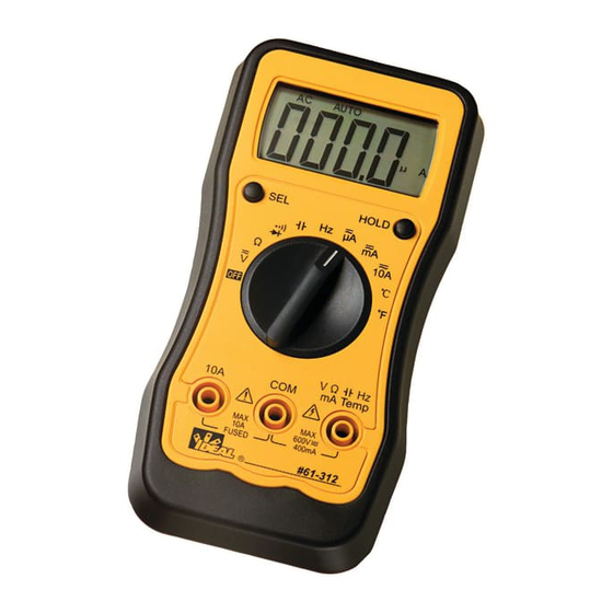
MODELS: 61-312
The Service Information provides the following information:
Precautions and safety information
●
Specifications
●
Basic maintenance (cleaning, replacing the battery and fuses)
●
Performance test procedures
●
Calibration and calibration adjustment procedures
●
Form Number: TM61312-4
Revision: 2. Date: August 2007
Form Number TM61312-4
61-314
Rev 2 Aug 2007
Advertisement
Table of Contents

Related Manuals for IDEAL INDUSTRIES 61-312


Summary of Contents for IDEAL INDUSTRIES 61-312
- Page 1 IDEAL INDUSTRIES, INC. TECHNICAL MANUAL MODELS: 61-312 61-314 The Service Information provides the following information: Precautions and safety information ● Specifications ● Basic maintenance (cleaning, replacing the battery and fuses) ● Performance test procedures ● Calibration and calibration adjustment procedures ●...
-
Page 2: Table Of Contents
TABL E OF CONTENTS Page Introduction Precautions and Safety Information Symbols Safety Specifications General Specification Measurement Characteristics Voltage Specification Current Specifications esistance, Diode, Cont inuity, Capacitance Specifications Frequency, Temperature Specification Auto Power Off, Data Hold hysical and Environmental C haracteristics Certifications and Compliances Required Equipment Basic Maintenance... -
Page 3: Introduction
The information provided in this document is for the use of qualified personnel only. Caution The 61-312 and 61-314 series contain parts that can be damaged by static discharge. Follow the standard practices for handling static sensitive devices. For add itional information about IDEAL INDUSTRIES, INC. -
Page 4: Safety
To avoid potential hazards, use the product only as specif ied. For operating instructions, see the 61-312 / 61-314 Digital Multimeter Instruction Manual. CAUTION: These statements identify conditions or practices that could result in damage to... -
Page 5: Specifications
Page 3 SPECIFICATIONS l specifications are warranted unless noted typical and apply to the 61-312 & 61-314 ated accuracies are at 23°C±5°C at less than 80% relative humidity and without the bat tery dicator displayed. eneral specifications Characteristics Description Display count... -
Page 6: Measurement Characteristics
40-400Hz 600V rms 1.2% + 5 1.5% + 5 400.0V 100mV 600V Input Impedance: 4.5MΩ Conversion Type: 61-312: Average sensing rms indication calibrated to the sine wave put. (2b) AC Volts (61-314 only) Over voltage Range Resolution Accuracy Protection 4.000V 40.00V... -
Page 7: Current Specifications
1μA 500mA, 250V Fast ±(1.2% reading + 5 digits)* Blow Fuse 40.00mA 10μA 400.0mA 0.1mA Overload Protection: mA Input: 500mA, 250V Fast Blow fuse. (61-312 / 61-314) (3b) DC Current (61-312 / 61-314) Range Resolution Accuracy Input Protection 4.000A .001mA 10A, 250V ±(1.5% reading + 5 digits) -
Page 8: R Esistance, Diode, Cont Inuity, Capacitance Specifications
40.00MΩ * 10KΩ ±(1.5% reading + 5 digits) pen circuit Voltage: -1.5V approx. < 5 digit of reading rolling. < 2% of reading rolling. (6) Diode Check and Continuity (for 61-312 / 61-314) Max. Test Max. Open Range Resolution Accuracy... -
Page 9: Frequency, Temperature Specification
250V rms (±0.3% + 4 digits) 100.0KHz 100Hz 1.000MHz 1KHz 5V rms 10.00MHz 10KHz (9) Temperature: Type K thermocouple (for 61-312 / 61-314) Overload Range Resolution Accuracy protection -20 to 300 ºC 1º ±1.0% + 4 301 to 750 ºC 1º... -
Page 10: Physical And Environmental Characteristics
Page 8 Physical and Environmental Characteristics Characteristics Description 150mm(H) ×76mm (W) ×38mm(D) (with holster) Dimensions (H×W×D) 5.9” (H) x 3.0”(W) x1.5”(D) Weight (with battery& holster) 0.219Kg (7.1 oz.) Environmental characteristics Description Temperature operating 0 to +40°C Non-Operating -20 to +60°C <80% R.H. Humidity (operating) <70% R.H. -
Page 11: Required Equipment
Page 9 Required Equipment quired equipment is listed in Table B. If the recommended models are not available, uipment with equivalent specifications may be used. pairs or servicing should be performed only by qualified personnel. ble B. Required Equipment Equipment Required Characteristics Recommended Model AC Voltage Range: 0... -
Page 12: Basic Maintenance
3. For Fuse replacement, follow instructions under Fuse Replacement section. Replacing the Battery e 61-312 Meter is powered by (2) AAA 1.5V batteries, e 61-314 Meter is powered by (1) 9V battery, types are, NEDA 1604, JIS006P, IEC 6F22 1. Remove the rubber holster 2. -
Page 13: Replacing Fuses
F314: 10A, 250V Fast Blow Fuse Fuse Replacement The 61-312 and 61-314 are fused in both the VmA input and 10A input port. The VmA input port is fused by a F312: 500mV, 250V FAST BLOW fuse. The 10A input port is fused by F314: 10A, 250V FAST BLOW fuse. -
Page 14: Performance Tests
61-312 / 61-314 Digital Multimeter Instruction Ma nual. Accuracy specifications are valid for a period of one year after calibration, when measured at an erating temperature of 18°C to 28°C and a maximum of 80% relative humidity. -
Page 15: T Esting The Voltage F Unction
Page 13 Testing the Voltage Function (for 61-312 / 61-314) To verify accuracy in the AC and DC voltage ranges, do the following: 1. Turn the rotary switch to “V ” position. Press the SEL Button to select the DC function 2. -
Page 16: T Esting The Dc Current Functio Ns
586 to 614 583 to 617 Testing the DC microamperes Function (for 61-312 and 61-314) To verify the accuracy of AC and DC current measurement functions, do the following: 1. Connect the calibrator to the VΩ Hz and COM inputs on the meter. - Page 17 400mA 300.0mA 295.9 to 304.1 Testing the DC ampere Function (for 61-312 and 61-314) 1. Connect the calibrator to the 10A and COM inputs on the meter. 2. Turn the rotary switch to A . a. Press the SEL button to select the DC function 3.
-
Page 18: Testing The Resistance Function
3000µA 400Hz 2950 to 3050 Testing the AC milliampere function: (for 61-312 and 61-314) 1. Connect the calibrator to the VΩ Hz and COM inputs on the meter. 2. Turn the rotary switch to mA a. Press the SEL button to select the AC function 3. -
Page 19: T Esting The Capacitance, Diode, C Ontinuity Functions
9.75 to 10.25 400Hz 9.75 to 10.25 Testing the Resistance Function (for 61-312 / 61-314) verify the accuracy of the resistance function, do the following: 1. Connect the calibrator to VΩ Hz and COM on the meter. 2. Turn the rotary switch to Ω. -
Page 20: Testing The Temperature Function
100.0µF 100.0µF 96.5 to 103.5 Checking the Diode Test Function (for 61-312 / 61-314) To check the diode test function, do the following: 1. Connect the DVM (Digital Voltage Meter) leads to the VΩ Hz and COM inputs on the meter. -
Page 21: Calibration
Page 19 Testing the Frequency Function (for 61-312 / 61-314) To verify the accuracy of the meter’s frequency function, do the following: 1. Connect the calibrator to the VΩ Hz and COM inputs on the meter. Note: The accuracy of the calibrator’s frequency function must be appropriate for the specified accuracy of the meter. - Page 22 Page 20 Testing the Temperature Function (for 61-312 / 61-314) To verify the accuracy of the meter’s frequency function, do the following: 1. Connect the calibrator to the VΩ Hz and COM inputs on the meter. 2. Set the rotary switch to the ºC or ºF as instructed in Table 8.
-
Page 23: Calibration Procedure
Page 21 Calibration Procedure calibrate your meter: is recommended that the multimeter be calibrated once each year. 1. P erform calibration at an ambient temperature of 23°C±2°C and a relative humidi ty of <70%. Disco nnect the test leads and turn the meter off. Remove the test leads from th front terminals. -
Page 24: Form Number Tm61312-4 Rev 2 Aug
Page 22 D) ºC Calibration (Adjust VR3) 1. Set the rotary switch to the "ºC " position. 2. Set the output of the calibrator to 0 ºC 3. Connect the calibrator temperature output to the V/Ω/Temp and COM input terminals 4. - Page 25 Page 23 Form Number TM61312-4 Rev 2 Aug 2007...
Need help?
Do you have a question about the 61-312 and is the answer not in the manual?
Questions and answers