Table of Contents
Advertisement
Quick Links
Advertisement
Table of Contents
Troubleshooting

Related Manuals for Chamberlain MIRACLE-1 Elite Series


Summary of Contents for Chamberlain MIRACLE-1 Elite Series
-
Page 1: Installation Instructions
INSTALLATION INSTRUCTIONS & MANUAL BOOK FOR ARCHITECTS, GENERAL CONTRACTORS & DEALERS REV-2 ® ® Applied Applied MODEL: MIRACLE•1 HIGH-QUALITY, MECHANICAL, LINEAR OPERATOR FOR SWING GATES © COPYRIGHT 1998 ELITE ACCESS SYSTEMS, INC. ™ ACCESS SYSTEMS INC... -
Page 2: Table Of Contents
TABLE OF CONTENTS ATTENTION: This handbook is exclusively for qualified installation personal, and assis- tance and/or maintenance service. - The performances indicated in this handbook are valid only if a correct assembly has been carried out. TABLE OF CONTENTS ............1 WARNINGS AND PRECAUTIONS . -
Page 3: Warnings And Precautions
WARNINGS AND PRECAUTIONS WARNING: TO REDUCE THE RISK OF INJURY TO PERSONS THE MIRACLE•1 IS FOR VEHICULAR GATE USE ONLY Be sure to read and follow all these important instructions before installation of the gate operator. Elite Access Systems, Inc. is not responsible for improper installations or failure to comply with local building and electrical codes. -
Page 4: Procedure For Installation
PROCEDURE FOR INSTALLATION Open To The Inside IMPORTANT: WELD RE-BAR BEHIND HINGES FOR MAXIMUM STRENGTH STEEL POST HEAVY STEEL PLATE 1/4" STEEL PLATE STEEL HEAVY STEEL (REINFORCE IF RE-BAR PLATE NECESSARY) TOP VIEW POST 10" MIN. MASONRY COLUMN HEAVY STEEL PLATE 10.5”... - Page 5 PROCEDURE FOR INSTALLATION Open To The Outside IMPORTANT: MASONRY WELD RE-BAR BEHIND COLUMN TOP VIEW HINGES FOR MAXIMUM POST STRENGTH STEEL HEAVY STEEL PLATE RE-BAR HEAVY STEEL 1/4" STEEL PLATE PLATE (REINFORCE IF NECESSARY) STEEL RE-BAR Indexing STEEL POST on Cen- tral Hole 90°/105°...
- Page 6 Procedure For Installation (cont.) STEP 1: REMOVE THE COVER - E - BY REMOVING STEP 2: RELEASE THE MECHANICAL LOCK BY 4 SCREWS. TURNING KEY - F - TO THE HORIZONTAL POSI- TION. TACK WELD BRACKET AND PLATE IN POSITION TACK WELD BRACKET IN POSITION...
- Page 7 Procedure For Installation (cont.) FULLY WELD ™ BRACKET AND ACCESS SYSTEMS INC PLATE FULLY WELD BRACKET IN POSITION STEP 4: REMOVE OPERATOR AND FULLY WELD STEP 5: MAKE SURE THE OPERATOR IS LEVEL THE PLATE AND BRACKETS TOP, BOTTOM AND OR THE OPERATOR WILL NOT FUNCTION PROP- SIDES.
-
Page 8: Procedure For Installation
Procedure For Installation (cont.) STEP 9: CARRY OUT ALL APPRO- PRIATE CONNECTIONS IN THE FOLLOWING PAGES OF THE MAN- UAL TO POWER THE UNIT. THEN GO TO STEP 10. STEP8: LOCK THE OPERATOR BY TURNING KEY - F - TO THE VERTICAL POSITION WHILE PUSHING OR PULLING ON THE GATE UNTIL YOU HEAR THE KEY RELEASE CLICK INTO PLACE. -
Page 9: Control Board Box & How To Remove Control Board
CONTROL BOARD BOX ST EM S INC AC CE SS SY Unpack Control Board Box. Cut the plastic tie holding the transformer in the box. Remove plastic tie and transformer. Place rubber bumper (supplied) over top hole. This will keep water from entering the Control Board Box. -
Page 10: Connecting Power
CONNECTING POWER CAUTION: Do not over-bend the wire connection from the operator. To do so will cause the wires to eventually break. WRONG WIRE GAUGE 16 AWG / 200 FT. MIRACLE - 1 rev 1.3 MAGLOCK ALARM SYSTEM REVERSE SENSOR ALARM SENSOR OPEN... -
Page 11: Connecting Power Master / Slave
CONNECTING POWER Master / Slave FIELD WIRING OPERATOR #2 OPERATOR #1 COMPARTMENT CONDUIT 6 WIRES FROM OPERATOR #2 INSIDE CONDUIT OPERATOR #2 WIRE GAUGE 16 AWG / 200 FT. MASTER SLAVE SYSTEM ON MAGLOCK ALARM REVERSE SENSOR ALARM SENSOR OPEN IN OPEN OUT POS. -
Page 12: Choosing Movement Direction
CHOOSING MOVEMENT DIRECTION Switch the “Open Inside / Open Outside” switch on the control board to the corresponding position for the proper direction. OPEN INSIDE OPEN OPEN INSIDE OUTSIDE OPEN OUTSIDE OPEN OPEN INSIDE OUTSIDE CURRENT SENSOR ADJUSTMENT Sensor Adjustment The sensors must be adjusted while the gate is in the opening or closing cycle. -
Page 13: Power Supply
POWER SUPPLY Use the plug-in transformer (sold by Elite Access System only) by hooking it up to 115V and use Two Conductor, low voltage, 14 gauge / 300 watt direct burial, landscape light- ing cables (part #A W-100 or A W-500). Connect these wires to the two yellow wires from operator connector(J3), to the plug-in transformer. -
Page 14: Dry Contact & Receiver Wiring
DRY CONTACT & RECEIVER WIRING STRIKE OPEN 12 & 7 Mount receiver inside the control board box as shown using velcro. Note that the receiver is mounted upside down so the antenna ™ can fit through the hole ST EM S IN AC CE SS SY at the bottom of the control board box. -
Page 15: Safety And Center Loop Installation
SAFETY & CENTER LOOP INSTALLATION Safety Loop TWISTED WIRES Center Loop FROM LOOP CUTS Safety Loop Center Loop BLUE YELLOW 16 15 14 13 12 11 10 9 1/4" YELLOW BLUE 1 1/2" 14 AWG "uf" GRADE STRANDED WIRE Safety Loop TWIST WIRES TO LOOP DETECTOR... -
Page 16: Photocell Installation
PHOTOCELL INSTALLATION TO REDUCE THE RISK OF INJURY, ELITE HIGHLY RECOMMENDS INSTALLING A PHOTOCELL SENSOR WHEN THE GATE OPENS TO LESS THAN 18” FROM A WALL OR ANY OTHER OBJECT. FOLLOW THE INSTALLATION INSTRUCTIONS PRO- VIDED WITH THE PHOTOCELL SENSOR FOR ACCURATE PLACEMENT OF THE PHOTOCELL AND THE REFLECTOR. GATE IS OPEN REFLECTOR PHOTOCELL... -
Page 17: Control Board Description
CONTROL BOARD DESCRIPTION 1. Open or Close Relay LED 15. Board Fuse 2. Control Relay LED 16. Replace Charging Power Fuse LED 3. Motor Fuse 17. Replace Board Power Fuse LED 4. J1-Batteries and Motor Connector 18. Timer Pot (3 to 60 sec.) 5. -
Page 18: Control Board Description Master / Slave
CONTROL BOARD DESCRIPTION Master / Slave 1. Open or Close Relay LED 15. Batteries Low LED 2. Control Relay LED 16. Charger Ok LED 3. Motor Fuse 17. Power LED 4. J1-Batteries and Motor Connector 18. Timer Pot (3 to 60 sec.) 5. -
Page 19: Maglock & Alarm Connectors
MAGLOCK & ALARM CONNECTORS Contact Data Contact Rating 125 VAC - 0.5 A Use the harness provided with the unit to make your connections to 1 2 3 these alarm outputs. MAGLOCK 1 2 3 4 Burglar Alarm Relay Output 1. -
Page 20: Burglar Alarm
BURGLAR ALARM USE LOW white ...HOUSE ALARM VOLTAGE white IMPORTANT: When interfacing with a WIRE 20 AWG house alarm you must install positive stops at the gate closed position. 12VDC HOUSE ALARM SYSTEM ALARM DRY CONTACT white white POWER FOR STROBE ALARM / STROBE 12VDC ALARM... -
Page 21: Gate Opening Inside Installation
GATE OPENING INSIDE INSTALLATION OF..MAGNETIC LOCK MAGNETIC CUSTOM LOCK MAGNETIC BRACKET PLATE LOCK GATE FENCE MAGLOCK Use this position for Opening Inside ...SOLENOID LOCK MAGLOCK POWER Use this position for MAGLOCK Opening Inside NOTE: Solenoid The optional relay harness, Lock allowing interface with an external devices, is available,... -
Page 22: Gate Opening Outside Installation
GATE OPENING OUTSIDE INSTALLATION OF..SOLENOID LOCK MAGLOCK ...MAGNETIC LOCK Leave it empty MAGLOCK Solenoid Lock User this POWER FOR position for SOLENOID Opening Outside NOTE: The optional relay harness, allowing interface with external devices, is available, only from Elite Access Systems POWER MAGLOCK... -
Page 23: Emergency Key Release
EMERGENCY KEY RELEASE UNLOCK STEP 1 To move the gate during an emergency or power failure, insert the (step 1) into the key release hole on the front of the operator. Turn the key counter- clockwise to release the gate. Move the gate manually (step 2) to the full open position. -
Page 24: Close Delay Option (Master / Slave Only) Opening Inside
CLOSE DELAY OPTION (Master / Slave only) This option is to be used when there is an master/slave installation with overlaping gates. MASTER SLAVE SYSTEM ON MAGLOCK ALARM OPEN IN OPEN OUT REVERSE SENSOR ALARM SENSOR POS. STOP POS. STOP OPEN IN OPEN OUT POS. -
Page 25: Close Delay Option (Master / Slave Only) Opening Outside
CLOSE DELAY OPTION (Master / Slave only) This option is to be used when there is an master/slave installation with overlaping gates. MASTER SLAVE SYSTEM ON MAGLOCK ALARM OPEN IN OPEN OUT REVERSE SENSOR ALARM SENSOR OPEN IN OPEN OUT POS. -
Page 26: Troubleshooting
TROUBLESHOOTING Check the fuses If the gate is not moving in any direction be sure to check all of the LED displays on the control board. If the board power or charging power LEDs are on, change the corresponding fuse on the right side of the board. MASTER / SLAVE MASTER SLAVE... -
Page 27: Troubleshooting
TROUBLESHOOTING Checking Control Options (example - Radio Receiver) CENTRAL CONTROL CENTRAL CONTROL STRIKE SAFETY RADIO CENTER STRIKE SAFETY RADIO CENTER OPEN LOOP LOOP OPEN LOOP LOOP Problem: Problem: The radio receiver LED is on and the The radio receiver LED is not on and the gate remains open. -
Page 28: Miracle•1 Parts List
MIRACLE•1 PARTS LIST ST EM S IN C. AC CE SS SY 24 VDC Battery Bolt Bushing Washer 1 - Control Board Nuts (set) 7 - Key Release 2 - Control Board 8A - Front Mounting Plate, 3 - Backup Batteries 8B - Back Mounting Plate 4 - Operator 9 - Motor Harness... -
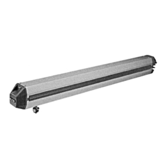
Page 29: Features And Specifications
FEATURES AND SPECIFICATIONS MECHANICAL SPECIFICATIONS ” Overall Dimensions MOTOR - 24V DC, 12 Amps. CYCLES - 100 / Day. 1 / 2 ” 4” SHIPPING WEIGHT: Single Unit: 58 lbs. - Master/Slave: 89 lbs TORQUE - 600 lbs. of torque. FINISHING - Aluminum.
Need help?
Do you have a question about the MIRACLE-1 Elite Series and is the answer not in the manual?
Questions and answers