Table of Contents
Advertisement
Advertisement
Table of Contents

Subscribe to Our Youtube Channel
Related Manuals for Chamberlain Miracle-One


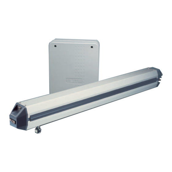
Summary of Contents for Chamberlain Miracle-One
-
Page 2: Table Of Contents
T A B L E T A B L E T A B L E C O N T E N T S C O N T E N T S C O N T E N T S Attention: This handbook is exclusively for qualified installation personnel, and assistance and/or maintenance service. -
Page 3: Ul Listings And Instructions
E T L E T L E T L L I S T I N G S L I S T I N G S L I S T I N G S A N D A N D A N D I N S T R U C T I O N S I N S T R U C T I O N S I N S T R U C T I O N S... - Page 4 E T L E T L E T L L I S T I N G S L I S T I N G S L I S T I N G S A N D A N D A N D I N S T R U C T I O N S I N S T R U C T I O N S I N S T R U C T I O N S...
- Page 5 E T L E T L E T L L I S T I N G S L I S T I N G S L I S T I N G S A N D A N D A N D I N S T R U C T I O N S I N S T R U C T I O N S I N S T R U C T I O N S...
- Page 6 E T L E T L E T L L I S T I N G S L I S T I N G S L I S T I N G S A N D A N D A N D I N S T R U C T I O N S I N S T R U C T I O N S I N S T R U C T I O N S...
-
Page 7: Role Of Specifiers And Designers
R O L E O F S P E C I F I E R S A N D D E S I G N E R S Specifiers and designers should design an automatic vehicular gate system to: • Incorporate UL 325 compliant equipment. -
Page 8: Role Of End Users / Home Owners
R O L E O F E N D U S E R S / H O M E O W N E R End users should be made aware that they must: • Contact a trained gate systems technician to maintain and repair the gate system (End users should never attempt to repair the gate) •... -
Page 9: Warnings And Precautions
W A R N I N G S W A R N I N G S W A R N I N G S A N D A N D A N D P R E C A U T I O N S P R E C A U T I O N S P R E C A U T I O N S Warning -... -
Page 10: Open To The Inside" Mounting Specifications
P R O C E D U R E F O R I N S T A L L A T I O N O p e n T h e I n s i d e Important: Weld Re-Bar Gate Hinge Gate Hinge Behind Gate... -
Page 11: Open To The Outside" Mounting Specifications
P R O C E D U R E F O R I N S T A L L A T I O N O p e n T h e O u t s i d e Important: Weld Re-Bar Gate Hinge Gate Hinge Behind Gate... -
Page 12: Step-By-Step Operator Mounting Instructions
P R O C E D U R E F O R I N S T A L L A T I O N M o u n t i n g I n s t r u c t i o n s Step 1: Step 2: Remove the 4 screws and lift the... - Page 13 P R O C E D U R E F O R I N S T A L L A T I O N M o u n t i n g I n s t r u c t i o n s Step 4 (con't): The gate must be in the closed position.
- Page 14 P R O C E D U R E F O R I N S T A L L A T I O N M o u n t i n g I n s t r u c t i o n s Step 8: Make sure that the operator is level or it will not function properly.
- Page 15 P R O C E D U R E F O R I N S T A L L A T I O N A d j u s t i n g t h e L i m i t S w i t c h e s Step 11: Adjust the travel distance of the gate with the limit switches.
-
Page 16: Removing The Control/Surge Suppressor Boards
R E M O V I N G T H E C O N T R O L / S U R G E B O A R D S Unscrew the 4 Phillips head screws from the cover. Unplug the J1 and J3 plugs. Unplug battery connector. -
Page 17: Wiring 1 Operator To The Surge Suppressor Board
® W I R I N G 1 O P E R A T O R T O B O A R D LAKE FOREST, CALIFORNIA www.eliteaccess.com Caution: Do Not over-bend the cord from the operator. Doing this will cause the wires to eventually break. -
Page 18: Wiring 2 Operators (Master/Second) To The Surge Suppressor Board
W I R I N G O P E R A T O R S M A S T E R S E C O N D ® LAKE FOREST, CALIFORNIA www.eliteaccess.com Water Tight 6 Wires, 16 AWG from operator in dedicated water tight J-Box Kit DO NOT run AC lines in same conduit! conduit. -
Page 19: Choosing Gate Movement Direction
C H O O S I N G G A T E M O V E M E N T D I R E C T I O N Switch the “Open Inside / Open Outside” switch on the control board to the corresponding position for the proper direction. -
Page 20: Adjustable Timer
A D J U S T A B L E T I M E R Timer On Set Timer 1 to 60 Seconds Timer Off If secondary safety sensor devices are not used when timer is ON, gate will hit vehicle obstructing gate path. E A R T H G R O U N D R O D I N S T A L L A T I O N Proper grounding gives an electrical charge, such as from an electrical static discharge or a near lightning strike, a... -
Page 21: Connecting Power Supply
Use low voltage direct burial landscape lighting cable, 14 gauge/300 watt not to exceed 500 ft or 10 AWG up to 1000 ft. The transformer must plug into 115 VAC. SINGLE OR MASTER ONLY SLAVE ONLY The Miracle-One MUST be properly grounded. MOTOR BRAKE LIMITS... -
Page 22: Wiring Additional Inputs
W I R I N G A D D I T I O N A L I N P U T S SLAVE ONLY Caution: Make sure MOTOR BRAKE LIMITS BARE WIRE makes good contact inside removable terminal connectors. DO NOT let wire insulation Removable Terminal Connectors interfere with connection. -
Page 23: Single Operator Loop Size And Placement
S I N G L E O P E R A T O R L O O P S I Z E A N D P L A C E M E N T It is VERY important to have enough separation between loops and gates to prevent false detection. “E”... -
Page 24: Master / Second Loop Size And Placement
M A S T E R / S E C O N D L O O P S I Z E A N D P L A C E M E N T It is VERY important to have enough separation between loops and gates to prevent false detection. “E”... -
Page 25: Loop Installation And Number Of Wire Turns
L O O P I N S T A L L A T I O N A N D N U M B E R O F W I R E T U R N S Loop Installation “Saw Cut” Type Mark the loop layout on the pavement. -
Page 26: Loop Detector Wiring
L O O P D E T E C T O R W I R I N G Safety Loop Center Loop Allows gate to stay open when vehicles Allows gate to stay open when vehicles are obstructing gate path. are obstructing gate path. -
Page 27: Photocell Installation
P H O T O C E L L I N S T A L L A T I O N To reduce the risk of injury, You must install a photocell sensor when the gate opens to less than 18” from a wall or any other object or potential entrapment installation. -
Page 28: Single Control Board Description
C O N T R O L B O A R D D E S C R I P T I O N 24 23 22 21 20 19 18 Open or Close Relay LED Board Fuse Control Relay LED Replace Charging Power Fuse LED Motor Fuse Replace Board Fuse LED... -
Page 29: Master / Second Control Board Description
C O N T R O L B O A R D D E S C R I P T I O N M a s t e r / S e c o n d Open or Close Relay LED Charge OK LED Control Relay LED Power LED... -
Page 30: Surge Suppressor Board Description
S U R G E S U P P R E S S O R B O A R D D E S C R I P T I O N ® LAKE FOREST, CALIFORNIA www.eliteaccess.com Master/Second J1 J3 Plug Surge Suppressor REV A Plug Shown... -
Page 31: Alarm / Maglock Control Board Connections
A L A R M & M A G L O C K C O N N E C T I O N S Relay Contact Rating 0.5 A - 125 VAC 1 A - 24 VDC Use the harness provided with the unit to make the connections to the alarm outputs. (Refer to next page) Maglock Connection (Optional) Alarm Connection UL Audio Alarm... -
Page 32: Ul Audio Alarm
A U D I O A L A R M This UL alarm is required per UL-325. It will go off after 2 consecutive events on reverse sensor or UL sensor. The UL alarm will sound for a period of 5 minutes or until a new command is received by the Strike Input Command ONLY. -
Page 33: Gate Opening Inside " Installation Of Maglock / Solenoid Relay
G A T E O P E N I N G “ I N S I D E ” I N S T A L L A T I O N O F . . . Control Board 1. Ground- Plug in white wire to open gate Inside 2. -
Page 34: Gate Opening Outside " Installation Of Maglock / Solenoid Relay
G A T E O P E N I N G “ O U T S I D E ” I N S T A L L A T I O N O F . . . Control Board 2. Power - Always plugged in (red wire) Ground- Plug in white wire to open gate Outside ...Magnetic Lock Wiring... -
Page 35: Close Delay Option (Master / Second Only)
C L O S E D E L A Y O P T I O N M a s t e r / S e c o n d O n l y This option is to be used when there is a Master/Second installation with overlapping gates. Opening “Inside”... - Page 36 C L O S E D E L A Y O P T I O N M a s t e r / S e c o n d O n l y This option is to be used when there is a Master/Second installation with overlapping gates. Opening “Outside”...
-
Page 37: Emergency Key Release
E M E R G E N C Y K E Y R E L E A S E Step 1: To move the gate during an emergency or power failure, insert key and turn counterclockwise to Unlock the Miracle 1 from the gate. Unlock Unlock Key Provided... -
Page 38: Troubleshooting
T R O U B L E S H O O T I N G Check the Fuses If the gate is not moving in any direction be sure to check all of the LED displays on the control board. If the board power or charging power LEDs are on, change the corresponding fuse on the right side of the board. - Page 39 T R O U B L E S H O O T I N G The Gate Will Not Close! For Toll Free Technical Support: 1-888-ELITE-10 Symptom: The radio receiver LED on the control board remains “ON” when using the remote control. Possible Solutions: Stuck remote Control Board LED...
- Page 40 T R O U B L E S H O O T I N G You will SEE the alarm LED “ON” when... For Toll Free Technical Support: 1-888-ELITE-10 Horizontal Gate Level line Incorrect Installation The gate is too heavy or the operator or gate is installed incorrectly. A foreign object is on the gate frame while the gate is moving.
-
Page 41: Optional Solar Power
SINGLE OR MASTER ONLY SECOND ONLY MOTOR BRAKE LIMITS MOTOR BRAKE LIMITS DC Power Adapter fits inside the Miracle-One electronic box Solar Panel Wires DC Power Adapter Elite Part # A SOLAR ADP Battery Connector from Miracle-One Connector from Miracle-One J1 Plug Contact your local dealer for more information. -
Page 42: Miracle 1 Accessories
M I R A C L E A C C E S S O R I E S 24V DC Radio Receiver Maglock/Solenoid Relay Adapter (Elite Part # 1090) (Elite Part # Q240 MAU) Solar Panel Transmitter (Elite Part # 3089) 24V Photo Electric Eye... -
Page 43: Miracle 1 Parts Illustration
M I R A C L E P A R T S ® LAKE FOREST, CALIFORNIA www.eliteaccess.com REV A SINGLE OR MASTER ONLY SLAVE ONLY MOTOR BRAKE LIMITS MOTOR BRAKE LIMITS ® Q310 LAKE FOREST, CALIFORNIA www.eliteaccess.com REV A SINGLE OR MASTER ONLY SLAVE ONLY A BT MIR MOTOR... -
Page 44: Miracle 1 Parts List / Maintenance
M I R A C L E P A R T S L I S T A BT MIR - Plastic Rack and 2 Batteries Q239 - Limit Switch Harness (Wires and 4 Limit Switches) A POW3 - Transformer (24 VAC) Q240 MAU - Maglock/Solenoid Relay Adapter A SOLAR ADP - DC Solar Power Adapter Q242 - Alarm Harness... - Page 46 F E A T U R E S F E A T U R E S F E A T U R E S A N D A N D A N D S P E C I F I C A T I O N S S P E C I F I C A T I O N S S P E C I F I C A T I O N S Mechanical Specifications...
- Page 47 S U R G E S U P P R E S S O R W I R I N G D I A G R A M SINGLE OR MASTER ONLY SECOND ONLY MOTOR BRAKE LIMITS MOTOR BRAKE LIMITS 9 10 11 12 13 14 15 16 Removable Terminal Connectors...
- Page 48 S U P P R E S S O R W I R I N G D I A G R A M Green Ground Wire The Miracle-One MUST be properly grounded. Please refer to the “Earth Ground Rod Installation” page 19. 14 15 16...
-
Page 49: Features And Specifications
F E A T U R E S A N D S P E C I F I C A T I O N S We suggest the following items manufactured by Chamberlain Professional Products for better and safer operations. MG-1300 MAGNETIC LOCKS Offering up to 1300 pounds of holding force and an attached junction box.
Need help?
Do you have a question about the Miracle-One and is the answer not in the manual?
Questions and answers
Gate will not work, will not move with keypad or remote. All fuses are checking out good and have power.
If a Chamberlain Miracle-One gate is not moving with the keypad or remote despite having power and good fuses, possible issues include:
1. The operator arm or gate is incorrectly installed.
2. An externally wired safety sensor has been triggered (e.g., photo beam blocked).
3. The gate is too heavy or obstructed by a foreign object.
4. Gate hinges are too tight, broken, or not moving freely.
5. The radio receiver LED on the control board remains "ON" — this could indicate a stuck remote or control board issue.
This answer is automatically generated
Where is the learn/ smart button located to program my Home Link in my truck.
The learn/smart button on the Chamberlain garage door opener is typically located on the back or side of the opener unit, near the antenna wire or light cover.
This answer is automatically generated