Icom iC-F3062T Instruction Manual
Hide thumbs
Also See for iC-F3062T:
- Instruction manual (48 pages) ,
- Service manual (36 pages) ,
- Servise manual (48 pages)
Table of Contents
Advertisement
Advertisement
Table of Contents

Related Manuals for Icom iC-F3062T


Summary of Contents for Icom iC-F3062T
- Page 1 INSTRUCTION MANUAL VHF TRANSCEIVER iF3062T/S UHF TRANSCEIVER iF4062T/S...
-
Page 2: Explicit Definitions
Icom, Icom Inc. and the Icom logo are registered trademarks of Icom Incorporated (Japan) in Japan, the United States, the United King- dom, Germany, France, Spain, Russia and/or other countries. - Page 3 CAUTION: MAKE SURE KEEP the flexible antenna and bat- the transceiver from the heavy rain, and Never im- tery pack are securely attached to the radio, and that the an- merse it in the water. The transceiver construction is water tenna and battery pack are dry before attachment.
-
Page 4: Table Of Contents
TABLE OF CONTENTS IMPORTANT ................i Transmitting an SDM ....24 ■ (Short Data Message) EXPLICIT DEFINITIONS ............i Position data transmission .........25 ■ PRECAUTIONS ..............i Printer connection ............26 ■ TABLE OF CONTENTS ............iii Digital ANI ..............26 ■ Auto emergency transmission ........26 ■... -
Page 5: Accessories
ACCESSORIES Supplied accessories Accessory attachments ■ ■ Flexible antenna The following accessories are supplied: Qty. Flexible antenna .............. 1 Connect the supplied flexible anten- Battery pack ..............1 na to the antenna connector. Belt clip ................1 Connector cover (with screw) ........ -
Page 6: D Battery Pack
ACCESSORIES Battery pack Belt clip To attach the battery pack: To attach the belt clip: Slide the battery pack on the back of the transceiver in the direc- Remove the battery pack if it is attached. tion of the arrow (q), then lock it with the battery release button. Slide the belt clip in the direction of the arrow until the belt •... -
Page 7: Accessories
ACCESSORIES Connector cover To detach the connector cover: To attach the connector cover: q Unscrew the screw using a phillips screwdriver. q Insert the connector cover into the multi-connector. w Detach the connector cover for the speaker-microphone or w Tighten the screw. head-set connector. -
Page 8: Panel Description
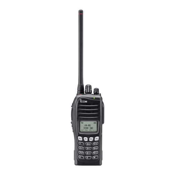
PANEL DESCRIPTION Front panel ■ q ROTARY SELECTOR Rotate to select the pre-programmed memory channels or the operating zone. (Depending on the pre-setting) w ANTENNA CONNECTOR Connects the supplied antenna. e DEALER-PROGRAMMABLE KEY [Emer] Desired functions can be programmed by your dealer. ((☞... - Page 9 PANEL DESCRIPTION i DEALER-PROGRAMMABLE KEYS [P0] to [P3] !1 BUSY/TRANSMIT INDICATOR Desired functions can be programmed independently by ➥ Lights green while receiving a signal, or when the your dealer. ((☞ p. 7)) squelch is open. Lights red while transmitting. ➥...
-
Page 10: Function Display
PANEL DESCRIPTION Function display ■ y BELL INDICATOR Appears/blinks when the specific 2/5-tone/BIIS code is re- ceived, according to the pre-programming. u CALL CODE MEMORY INDICATOR Appears when the call code memory is selected. i BATTERY INDICATOR Indicates remaining battery power. Indication Charging Battery level... -
Page 11: Programmable Function Keys
For function keys. example, ‘Staff A’ and ‘Staff B’ are assigned into a “Busi- Consult your Icom dealer or system operator for details con- ness” zone, and ‘John’ and ‘Cindy’ are assigned into a “Pri- cerning your transceivers programming. - Page 12 PANEL DESCRIPTION SCAN ADD/DEL (TAG) KEY “SCAD” LOCK KEY “LOCK” Push to add or delete the selected channel to/from the scan Push and hold for 1 sec. to electronically lock all program- ➥ group. mable keys except the following: [Call] (incl. Call A and Call B), [Moni(Audi)] and [Emergen- PRIO A/B KEYS “PRA”...
- Page 13 [CH Down] or 10-keypad*. ((☞ p. 14)) • Call transmission is necessary before you call another station de- *IC-F3062T/IC-F4062T (10-key type) only pending on your signaling system. • [Call A] and/or [Call B] may be available when your system employs TX CODE CHANNEL SELECT KEY “TXC”...
-
Page 14: Panel Description
PANEL DESCRIPTION ID-MR SELECT KEY “IDMS” OPT MOMENTARY KEYS “O1M” “O2M” “O3M” (PMR or BIIS PMR operation only) Push and hold to control the output signal level of the optional Recalls detected ID codes. ports in the optional unit connector. ➥... -
Page 15: Basic Operation
BASIC OPERATION Turning power ON ■ Battery type selection Prior to using the transceiver for the first time, the battery pack must be fully charged for optimum life and operation. The battery type must be selected according to the attaching ((☞... -
Page 16: Channel Selection
BASIC OPERATION Channel selection Call procedure ■ ■ Several types of channel selections are available. Methods When your system employs tone signaling (excluding CTC- may differ according to your system set up. SS and DTCS), the call procedure may be necessary prior to voice transmission. -
Page 17: Receiving And Transmitting
BASIC OPERATION Receiving and transmitting ■ Transmitting notes NOTE: Transmitting without an antenna may damage the transceiver. See page 1 for accessory attachments. • Transmit inhibit function The transceiver has several inhibit functions which restrict Receiving: transmission under the following conditions: Rotate [VOL] to turn the power ON. -
Page 18: D Tx Code Channel Selection
Push [Call] or [PTT] to transmit the edited TX code. • The LCD indication does not change when the operating channel number (or name) is displayed. (Depending on *IC-F3062T/IC-F4062T (10-key type) only the pre-setting) • To check the selected TX code, push [TX Code CH Se-... -
Page 19: D Dtmf Transmission
• When the 10-keypad* is used for setting, the digit to the right will blink automatically without pushing [TX Code CH Enter]. y Repeat r and t to input all allowable digits. u Push [Call] or [PTT] to transmit the edited TX code. *IC-F3062T/IC-F4062T (10-key type) only... -
Page 20: User Set Mode
BASIC OPERATION User set mode Scrambler function ■ ■ You can “customize” the transceiver operation to suit your pref- The voice scrambler function provides private communication erences and operating style. between stations. The frequency inversion type is equipped to all versions, moreover, the optional Rolling or Non-rolling Entering the user set mode: type can be available. -
Page 21: Biis Operation
BIIS OPERATION Setting example Receiving a call ■ ■ Individual call The following functions are assigned to each programmable key for display example. However, the assigned function can When an individual call is received; be changed by your dealer. Ask your dealer for details. •... -
Page 22: D Group Call
BIIS OPERATION Group call Displaying the received call record — Queue indication When a group call is received; • Beeps sound. The transceiver memorizes the calling station ID in the mem- • “ ” appears and the mute is released. ory. -
Page 23: Transmitting A Call
BIIS OPERATION Transmitting a call ■ Calling back from the queue channel A total of 3 ways for code selection are available—selecting the call code from memory, entering the call code from the While in the standby condition, push and hold [Digital But- keypad and calling back from the queue channel record. -
Page 24: D Direct Code Entry
• Digit for editing differs according to the setting. Set the desired digit using [CH Up]/[CH Down] or 10-key- pad*. *IC-F3062T/IC-F4062T (10-key type) only Push [TX Code Enter] to set the digit, then the digit to the right will blink automatically. -
Page 25: Receiving A Message
BIIS OPERATION Receiving a message ■ Receiving a status message Receiving an SDM (Short Data Message) When a status message is received; When an SDM is received; • Beeps sound. • Beeps sound. • The calling station ID (or text) and the status message is dis- •... -
Page 26: D Received Message Selection
BIIS OPERATION Received message selection The transceiver memorizes the received message in the Push [CH Up] or [CH Down] to select the desired mes- memory. Up to 6 messages for status and SDM, or 95 charac- sage. ter SDM’s can be memorized. The oldest message is erased •... -
Page 27: Transmitting A Status
BIIS OPERATION Transmitting a status ■ General Transmitting a status The status message can be selected with the programmed While in the standby condition, push [Digital Button], then text, and the message text is also displayed on the function push [CH Up] or [CH Down] to select the desired station/ display of the called station. -
Page 28: D Programming An Sdm Memory
(Short Data Message) General Programming an SDM memory (IC-F3062T/IC-F4062T (10-key type) only) The short data message, SDM, can be sent to an individual station or group stations. Also, 8 SDM memory channels are During standby condition, push [Digital Button] twice, then... -
Page 29: Position Data Transmission
BIIS OPERATION Position data transmission ■ • Available characters When the optional cable (OPC-966) and a GPS receiver is connected to the transceiver, the position (longitude and lati- Characters tude) data can be transmitted automatically. ’ ” , : _ ( ) < > Ask your dealer or system operator for connection details. -
Page 30: Printer Connection
BIIS OPERATION Printer connection Auto emergency transmission ■ ■ When the optional cable is connected to the transceiver, a When [Emergency Single (Silent)] or [Emergency Repeat (Si- printer can be connected to print out the received SDM con- lent)] is pushed, an emergency signal is automatically trans- tent and the ID of the station who sent the message. -
Page 31: Biis Indication
BIIS OPERATION BIIS indication ■ The following indications are available for the BIIS operation on a BIIS channel. CONNECT : Individual/group call is successful. : Message (status or SDM) transmission is suc- cessful. : No answer back is received. FAILED : Appears during retry of the call (2nd call). -
Page 32: Battery Charging
• R DANGER! NEVER incinerate used battery packs since internal battery gas may cause them to rupture, or may • R DANGER! Use and charge only specified Icom battery cause an explosion. packs with Icom radios or Icom charger. Only Icom battery •... -
Page 33: D Charging Caution
• CAUTION: DO NOT charge the battery outside of the speci- about half, then keep it safely in a cool dry place with the fied temperature range: BC-160 (0˚C to +40˚C). Icom rec- temperature range as below: ommends charging the battery at +20˚C. The battery may –20˚C to +50˚C (within a month) -
Page 34: Optional Battery Chargers
BATTERY CHARGING Optional battery chargers ■ Rapid charging with the BC-160 D Regular charging with the BC-171 The optional BC-160 provides rapid charging of the Li-ion The optional BC-171 provides regular charging of the Li-ion battery pack. battery pack. Charging period: Approximately 3 hours (with BP-232H) Charging period: Approximately 4 hours (with BP-230N) The following items are additionally required: The following items are additionally required:... - Page 35 BATTERY CHARGING AD-106 installation Rapid charging with the BC-119N+AD-106 The AD-106 must be installed into the BC- The optional BC-119N provides rapid charging of the Li-ion charger adapter 119N or BC-121N before battery charging. battery pack. Charging period: Approximately 3 hours (with BP-232H) q Attach the plugs from the BC-119N/BC-121N to the AD- The following items are additionally required.
-
Page 36: Battery Charging
BATTERY CHARGING Rapid charging with the BC-121N+AD-106 IMPORTANT!: Battery charging caution Ensure the guide tabs on the battery pack are correctly The optional BC-121N allows up to 6 battery packs to be aligned with the guide rails inside the charger adapter. charged simultaneously. -
Page 37: Battery Case
BATTERY CASE Optional battery case (BP-240) ■ When using the optional battery case attached to the trans- Fig.1 ceiver, install 6 × AAA (LR03) size alkaline batteries as illus- BP-240 trated at right. Unhook the battery cover release hook ( q), and open the cover in the direction of the arrow (w). -
Page 38: Swivel Belt Clip
SWIVEL BELT CLIP MB-93 contents Clip the belt clip to a part of your belt. And insert the trans- ■ ceiver into the belt clip until the base clip inserted fully into the groove. Qty. Belt clip ................1 Base clip ................ -
Page 39: Detaching
SWIVEL BELT CLIP Detaching ■ Turn the transceiver upside down in the direction of the Remove the battery pack if it is attached. (( ☞ p. 2)) arrow and pull out from the belt clip. Pinch the clip ( q), and slide the base clip in the direction of the arrow (w). -
Page 40: Speaker Microphone
SPEAKER MICROPHONE Optional HM-169/170GP To attach ■ ■ description Attach the connector of the speaker-microphone into the multi connector on the transceiver and tighten the screw. TOP KEY GPS ANTENNA (for HM-170GP only) (for HM-170GP only) CAUTION: Attach Desired functions can Microphone multi connector snugly, but be programmed by... -
Page 41: Options
OPTIONS D BATTERY PACKS • BC-160 + BC-145S desktop charger ac adapter For rapid charging of battery pack. A power adapter is sup- Battery pack Voltage Capacity Battery life* plied with the charger, depending on versions. 950 mAh (min.) Charging time: Approximately 3 hours for the BP-232H. BP-230N 7.4 V 7.35 hrs. - Page 42 VS-1SC : VOX/PTT switch box for hands-free operation, etc. Icom is not responsible for the destruction or damage to an HS-94 : Ear-hook type Icom transceiver in the event it is used with equipment that is HS-95 : Neck-arm type not manufactured or approved by Icom.
- Page 43 About VS-1SC D VOX gain and delay adjustment ptt case The VS-1SC is a VOX/PTT unit for Icom handheld transceiv- q Attach the connector of the VS-1SC into the multi-connec- ers, and allows you hands-free operation. tor on the transceiver, and tighten the screw.
-
Page 44: Options
OPTIONS • VOX Delay The VOX delay time can be set to between 0.5 and 3.0 sec- onds (in 0.5 second steps). The VOX Delay is the amount of time the transmitter stays ON after you stop speaking. [Side2] VOX DLY0.5 VOX DLY3.0 Push [Side3]... -
Page 45: Country Code List
COUNTRY CODE LIST • ISO 3166-1 Country Codes Country Codes Austria Liechtenstein Belgium Lithuania Bulgaria Luxembourg Croatia Malta Czech Republic Netherlands Cyprus Norway Denmark Poland Estonia Portugal Finland Romania France Slovakia Germany Slovenia Greece Spain Hungary Sweden Iceland Switzerland Ireland Turkey Italy United Kingdom... - Page 46 MEMO...
- Page 47 MEMO...
- Page 48 < Intended Country of Use > A-6489D-1EU-e Printed in Japan 2006–2014 Icom Inc. © 1-1-32 Kamiminami, Hirano-ku, Osaka 547-0003, Japan Printed on recycled paper with soy ink.
Need help?
Do you have a question about the iC-F3062T and is the answer not in the manual?
Questions and answers