Table of Contents
Advertisement
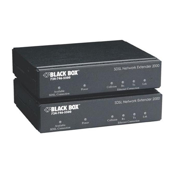
SDSL Network Extender 2000
CUSTOMER SUPPORT INFORMATION
Order toll-free in the U.S.: Call 877-877-BBOX (outside U.S. call 724-746-5500)
FREE technical support 24 hours a day, 7 days a week: Call 724-746-5500 or fax 724-746-0746
Mailing address: Black Box Corporation, 1000 Park Drive, Lawrence, PA 15055-1018
Web site: www.blackbox.com • E-mail: info@blackbox.com
P o w
l e
i l a b
o n
e c t i
A v a
o n n
L C
S D S
P o w
l e
i l a b
o n
e c t i
A v a
o n n
L C
S D S
NOVEMBER 2002
LR0020A-KIT-R2
t w o
L N e
v i d e
S D S
P r o
R x
n
l i s i o
e r n
C o l
E t h
e r
t w o
L N e
s c r i
S D S
S u b
R x
n
l i s i o
e r n
C o l
E t h
e r
d e r
x t e n
r k E
i t
r U n
L n k
T x
o n
e c t i
o n n
e t C
d e r
x t e n
r k E
U n i t
b e r
L n k
T x
o n
e c t i
o n n
e t C
Advertisement
Table of Contents

Related Manuals for Black Box 2000


Summary of Contents for Black Box 2000
- Page 1 Order toll-free in the U.S.: Call 877-877-BBOX (outside U.S. call 724-746-5500) FREE technical support 24 hours a day, 7 days a week: Call 724-746-5500 or fax 724-746-0746 Mailing address: Black Box Corporation, 1000 Park Drive, Lawrence, PA 15055-1018 Web site: www.blackbox.com • E-mail: info@blackbox.com...
- Page 2 FCC/IC STATEMENTS FEDERAL COMMUNICATIONS COMMISSION AND INDUSTRY CANADA RADIO-FREQUENCY INTERFERENCE STATEMENTS This equipment generates, uses, and can radiate radio-frequency energy and if not installed and used properly, that is, in strict accordance with the manufacturer’s instructions, may cause interference to radio communication. It has been tested and found to comply with the limits for a Class A computing device in accordance with the specifications in Subpart J of Part 15 of FCC rules, which are designed to provide reasonable protection against such interference...
- Page 3 This equipment complies with the requirements of the European EMC directive 89/336/EEC. TRADEMARKS USED IN THIS MANUAL BLACK BOX and the logo are registered trademarks of Black Box Corporation. Any other trademarks mentioned in this manual are acknowledged to be the property of the trademark owners.
- Page 4 NOM STATEMENT NORMAS OFICIALES MEXICANAS (NOM) ELECTRICAL SAFETY STATEMENT INSTRUCCIONES DE SEGURIDAD 1. Todas las instrucciones de seguridad y operación deberán ser leídas antes de que el aparato eléctrico sea operado. 2. Las instrucciones de seguridad y operación deberán ser guardadas para referencia futura.
- Page 5 SDSL NETWORK EXTENDER 2000 10. El equipo eléctrico deber ser situado fuera del alcance de fuentes de calor como radiadores, registros de calor, estufas u otros aparatos (incluyendo amplificadores) que producen calor. 11. El aparato eléctrico deberá ser connectado a una fuente de poder sólo del tipo descrito en el instructivo de operación, o como se indique en el...
-
Page 6: Table Of Contents
Page Specifications ................. 6 Introduction ................9 Installation ................10 3.1 The Complete Package ..........10 3.2 The Installation Procedure ........10 Operation ................16 Troubleshooting ..............18 5.1 Calling Black Box ............18 5.2 Shipping and Packaging ..........19... -
Page 7: Specifications
SDSL NETWORK EXTENDER 2000 1. Specifications Compliance — EMI/RFI: CE (EN 55022), FCC Part 15 Subpart J Class A, IC Class/classe A, CSA C108.8 Safety: UL ® 1950, CSA C22.2 No. 950, EN 60950, IEC 950 Standard — IEEE 802.3 Ethernet v2 Interfaces —... - Page 8 CHAPTER 1: Specifications On Provider Unit: (1) Rear-mounted User Controls – 3-position DIP switch for data rate Indicators — (6) Front-mounted LEDs on each Provider or Subscriber Unit: SDSL Connection, Power, Ethernet Collision, Ethernet Rx, Ethernet Tx, and Ethernet Link Connectors —...
- Page 9 SDSL NETWORK EXTENDER 2000 For each Provider or Subscriber Unit: From Power — utility-power (mains) outlet, through detachable input cord and external wallmount power supply: Input: 100 to 125 VAC (1 amp) at 47 to 63 Hz; Output: 5 VDC at a maximum of 1.5 amps;...
-
Page 10: Introduction
CHAPTER 2: Introduction 2. Introduction With the SDSL Network Extender 2000, you can create a long-distance Ethernet connection over your own private telephone wiring using Symmetric Digital Subscriber Line (SDSL) technology, which is far faster than regular dialup, leased-line, or even ISDN links. -
Page 11: Installation
SDSL NETWORK EXTENDER 2000 3. Installation 3.1 The Complete Package The SDSL Network Extender 2000 comes with a Provider Unit, a Subscriber Unit, a power supply for each Unit, and this manual. (The power supplies are identical; you can use either one with either unit.) If you didn’t receive everything, or if anything arrived... - Page 12 CHAPTER 3: Installation Table 3-1. Available DIP-switch settings and the corresponding maximum distances and data rates. Pos. Pos. Pos. Maximum Maximum Bandwidth Distance Down Down Down 2.32 Mbps 11,300 ft. (3444 m); Down Down Up 2.064 Mbps 12,200 ft. (3719 m); Down Up Down 1.552 Mbps 12,800 ft.
- Page 13 SDSL NETWORK EXTENDER 2000 NOTE While both ends of the Ethernet connection must have the same duplex mode configuration, partner Provider Units and Subscriber Units don’t have to be configured the same. Duplex mode does not apply to the SDSL connection.
- Page 14 CHAPTER 3: Installation 5. Plug your SDSL cable into the RJ-45 jack marked “SDSL” on the Unit’s rear panel. (This jack is designed to accept either RJ-45 or RJ-11 plugs. The SDSL cable should be 22 to 26 AWG telephone cable with Ring and Tip on the center two pins: If it has RJ-45 connectors, Ring should be on Pin 4 and Tip should be on Pin 5.
- Page 15 SDSL NETWORK EXTENDER 2000 NOTES The length and quality of the cabling between the Units directly affects the process by which they establish an SDSL link with each other. Depending on these cable characteristics, it might take anywhere from one to five minutes for the Units to establish the link.
- Page 16 Black Box Technical Support. 9. Perform step 8 at the other site with your Subscriber Unit.
-
Page 17: Operation
SDSL NETWORK EXTENDER 2000 4. Operation While the SDSL Network Extender 2000 is operating, you can inspect the front-panel LEDs on its Units at any time for status information: Meaning Connection Pulses green once per second to show that the SDSL connection is operational and the Unit is receiving either valid data packets or status packets from the other Unit. - Page 18 CHAPTER 4: Operation Meaning Link While Rx and Tx flash, steadily lit green to show that an Ethernet link is in place. While Rx and Tx are steadily lit, steadily lit green to show that no SDSL connection is present.
-
Page 19: Troubleshooting
5. Troubleshooting 5.1 Calling Black Box If you determine that your SDSL Network Extender 2000 is malfunctioning, do not attempt to alter or repair it. None of its components contain user-serviceable parts. Contact Black Box Technical Support at 724-746-5500. Before you do, make a record of the history of the problem. - Page 20 2/02 © Copyright 2002. Black Box Corporation. All rights reserved. 1000 Park Drive • Lawrence, PA 15055-1018 • 724-746-5500 • Fax 724-746-0746...
-
Page 21: Shipping And Packaging
If you need to transport or ship an Extender Unit: • Package it carefully. We recommend that you use the original container. • Before you ship it back to Black Box for repair or return, contact us to get a Return Authorization (RA) number. - Page 22 2/02 © Copyright 2002. Black Box Corporation. All rights reserved. 1000 Park Drive • Lawrence, PA 15055-1018 • 724-746-5500 • Fax 724-746-0746...
Need help?
Do you have a question about the 2000 and is the answer not in the manual?
Questions and answers