Black Box ACX1MR Series Manual

Black Box ACX1MR Series Manual

Servswitch dkm modular housings and tx/rx interface modules
Hide thumbs Also See for ACX1MR Series:
Table of Contents

Advertisement

Quick Links

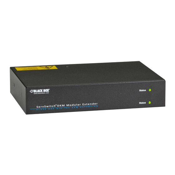
ServSwitch DKM Modular Housings and TX/RX Interface Modules
Increase the distance between a source (computer,
CPU) and its console (keyboard, mouse, and other
peripheral devices).
Models available for CATx or fiber.
Customer
Support
Information
ACX1MT
Order toll-free in the U.S.: Call 877-877-BBOX (outside U.S. call 724-746-5500)
FREE technical support 24 hours a day, 7 days a week: Call 724-746-5500 or fax 724-746-0746
Mailing address: Black Box Corporation, 1000 Park Drive, Lawrence, PA 15055-1018
Web site: www.blackbox.com • E-mail: info@blackbox.com
ACXMODH2
ACXMODH4R
ACXMODH2R
ACXMODH6R
ACXMODH4
ACXMOD21R
BLACK BOX
ACXMODH-RMK
ACX1MT Series
ACX1MR Series
®

Advertisement

Table of Contents
loading
Need help?

Need help?

Do you have a question about the ACX1MR Series and is the answer not in the manual?

Questions and answers

Summary of Contents for Black Box ACX1MR Series

  • Page 1 Order toll-free in the U.S.: Call 877-877-BBOX (outside U.S. call 724-746-5500) Customer FREE technical support 24 hours a day, 7 days a week: Call 724-746-5500 or fax 724-746-0746 Support Mailing address: Black Box Corporation, 1000 Park Drive, Lawrence, PA 15055-1018 Information Web site: www.blackbox.com • E-mail: info@blackbox.com ACX1MT...
  • Page 2 Trademarks Used in this Manual Trademarks Used in this Manual Black Box and the Double Diamond logo are registered trademarks of BB Technologies, Inc. Mac is a registered trademark of Apple Inc. TOSLINK is a registered trademark of Toshiba Corp.
  • Page 3 FCC and IC RFI Statements/WEEE/RoHS Federal Communications Commission and Industry Canada Radio Frequency Interference Statements This equipment generates, uses, and can radiate radio-frequency energy, and if not installed and used properly, that is, in strict accordance with the manufacturer’s instructions, may cause inter ference to radio communication. It has been tested and found to comply with the limits for a Class A computing device in accordance with the specifications in Subpart B of Part 15 of FCC rules, which are designed to provide reasonable protection against such interference when the equipment is operated in a commercial environment.
  • Page 4 NOM Statement Instrucciones de Seguridad (Normas Oficiales Mexicanas Electrical Safety Statement) 1. Todas las instrucciones de seguridad y operación deberán ser leídas antes de que el aparato eléctrico sea operado. 2. Las instrucciones de seguridad y operación deberán ser guardadas para referencia futura. 3.
  • Page 5 • Do not attempt to open or repair a power supply unit. • Do not attempt to open or repair the DKM Modular Extender. There are no user-serviceable parts inside. • If there is a fault, contact Black Box Technical Support at 724-746-5500 or info@blackbox.com. 724-746-5500 | blackbox.com...
  • Page 6: Table Of Contents

    Table of Contents Contents 1. Specifications..................................8 1.1 Interfaces ..................................8 1.1.1 DVI-D Single Link ..............................8 1.1.2 DVI-I Single Link ..............................8 1.1.3 USB-HID ................................8 1.1.4 USB 2.0 (Transparent) ............................8 1.1.5 RJ-45 (Interconnect) ............................8 1.1.6 Fiber SFP Type LC (Interconnect) ......................... 8 1.1.7 Serial Interface ..............................
  • Page 7 6.5 Digital Audio Upgrade Module ........................... 45 6.6 USB-HID Upgrade Module ............................46 6.7 USB 2.0 Upgrade Module ............................47 Technical Support ................................48 7.1 Contacting Black Box..............................48 7.2 Shipping and Packaging .............................. 48 8. Glossary ..................................49 724-746-5500 | blackbox.com...
  • Page 8: Specifications

    The communication of fiber devices is performed via Gigabit SFPs that have to be connected to suitable fibers fitted with type LC connectors (see Chapter 1.2.2). NOTE: The correct function of the device can only be guaranteed with SFPs provided by Black Box. CAUTION: SFP modules can be damaged by electrostatic discharge (ESD).
  • Page 9: Serial Interface

    Chapter 1: Specifications When handling, take care not to damage devices. 1.1.7 Serial Interface The serial interface option supports a full-duplex transmission with a real hardware handshake up to a baud rate of 19,200. The CON module is cabled as DTE (Data Terminal Equipment, such as CPU output) and can be connected directly to DCE (Data Communication Equipment) devices.
  • Page 10: Digital Audio Interface

    Chapter 1: Specifications • The output of the CPU module is connected to the audio input of the sound card (blue). Choose this connection if the microphone has its own pre-amplifier. NOTE: The CON module can do the pre-amplification of the microphone as well. Open the CON module, locate the “MIC” jumper on the audio board and close the pins.
  • Page 11: Interconnect Cable

    Chapter 1: Specifications Table 1-3. Digital audio interface specifications. Specification Description Compatibility AES/EBU, S/PDIF, EIAJCP1201, IEC 60958 Standards Dolby digital, DTS, PCM • Mini XLR (AES/EBU; symmetrical lockable) CPU Unit (Inputs) • Coaxial (S/PDIF; RCA, Cinch) • Optical (S/PDIF, TOSLINK ®...
  • Page 12: Fiber

    Chapter 1: Specifications Maximum Acceptable Cable Length Table 1-5. Maximum acceptable CATx cable length. Cable Type Maximum Length Solid-conductor 24 AWG CATx cable 400 feet (140 m) Stranded-conductor 26/28 or 27/28 AWG or CATx cable 200 feet (70 m) 1.2.2 Fiber A point-to-point connection is necessary.
  • Page 13: Supported Peripherals

    DKM Modular Extender models featuring a transparent USB 2.0 connection use Extreme USB Technology. This technology supports all types of USB 2.0 devices; however, we cannot guarantee compatibility with every device on the market. Please contact Black Box Technical Support at 724-746-5500 or info@blackbox.com if any issues are found. 1.4 Connector Pinouts Figure 1-1.
  • Page 14 Chapter 1: Specifications Connector DVI-I Single-Link Figure 1-2. DVI-I connector. Table 1-9. DVI-I single-link connector pinout. Signal Signal Signal TMDS data 2- TMDS data 1- TMDS data 0- TMDS data 2+ TMDS data 1+ TMDS data 0+ TMDS data 2 GND TMDS data 1 GND TMDS data 0 GND Not connected...
  • Page 15 Chapter 1: Specifications Connector USB Type A Figure 1-4. USB Type A connector. Table 1-11. USB Type A connector pinout. Signal Color VCC (+5 VDC) Data - White Data + Green Black Connector Mini USB Type B Figure 1-5. Mini USB Type B connector. Table 1-12.
  • Page 16 Chapter 1: Specifications Fiber SFP Type LC Figure 1-7. SFP Type LC connector. Table 1-14. SFP Type LC connector pinout. Signal Data OUT Data IN Power Supply Figure 1-8. Power supply label. Table 1-15. Power supply connector pinout. Signal Inside VCC (+5 VDC) Outside DB9 (Serial)
  • Page 17 Chapter 1: Specifications 3.5-mm Stereo Jack Plug Figure 1-10. 3.5-mm stereo jack plug. Table 1-17. 3.5-mm stereo jack plug pinout. Signal Audio IN/OUT L Audio IN/OUT R RCA (Cinch) Figure 1-11. RCA connector. Table 1-18. RCA connector pinout. Signal Data IN/OUT Mini-XLR Figure 1-12.
  • Page 18: Power Supply

    Chapter 1: Specifications TOSLINK Figure 1-13. TOSLINK connector. Table 1-20. TOSLINK connector pinout. Signal Data IN/OUT 1.5 Power Supply Power — ACXMODH2/4: 5 VDC; ACXMODH6R/21R: 100-240 VAC; ACX1MT, ACX1MR models: 5-VDC; Basic modules: Single-head devices: 800 mA max., VGA: 900 mA max.; Upgrade modules: Analog audio/serial 300 mA max., Digital audio: 300 mA max., USB-HID: 300 mA max.;...
  • Page 19: Shipping Weight

    Chapter 1: Specifications 1.8 Shipping Weight 2-port chassis (Empty): CPU Module/CON Module — 0.6 lb. (0.3 kg) Shipping Box — 4.9 lb. (2.2 kg) 4-port chassis (Empty): CPU Module/CON Module — 0.9 lb. (0.45 kg)) Shipping Box — 7.5 lb. (3.4 kg) 6-port chassis (Empty): CPU Module/CON Module —...
  • Page 20: Overview

    Chapter 2: Overview 2. Overview 2.1 Application The DKM Modular Extender is used to increase the distance between a source (computer, CPU) and its console (keyboard, mouse, and other peripheral devices). It’s designed for use with CATx (twisted-pair) interconnect cables or fiber interconnect cables. The DKM Modular Extender with CATx interconnect cables won’t work between buildings where you should use a fiber optic based product instead.
  • Page 21: Product Range

    Chapter 2: Overview Table 2-1. System components. Number Component Source (computer, CPU) DKM Modular Extender CPU unit Interconnect cable DKM Modular Extender CON unit Console (monitor, keyboard, mouse) Second monitor (option, only with additional basic module USB-HID devices (option, only with USB-HID upgrade module NOTE: See Section 3.3 for installation examples.
  • Page 22: Usb 2.0 Modules

    Chapter 2: Overview 2.3.3 USB 2.0 Modules Table 2-4. USB 2.0 modules. Part Number Description ACX1MT-U2-xx USB 2.0 module with (4) USB 2.0 ports ACX1MR-U2-xx Part numbers for connections via CATx or fiber cable: All mentioned devices are available in the following versions: •...
  • Page 23: Accessories

    Chapter 2: Overview 2.5 Accessories Table 2-6. Accessories. Part Number Description BC00200 6-foot (1.8-m) serial RS-232 cable USB05-0006 6-foot (1.8-m) USB Type A to B cable ACXMODH4-PS 100–240-VAC/5-VDC/5-A international power supply unit ACXMODH2-PS 100–240-VAC/5-VDC/3-A international power supply unit EVNDVI04-0006 6-foot (1.8-m) VGA cable (VGA to DVI-I) EVNDVI02-0006 6-foot (1.8-m) DVI-D cable (DVI-D) ACXSPL12...
  • Page 24: 4-Slot Dkm Modular Chassis (Cpu And Con Modules)

    Chapter 2: Overview 2.6.2 4-Slot DKM Modular Chassis (CPU and CON Modules) Figure 2-3. 4-slot modular chassis (CPU and CON module) (ACXMODH4R). Table 2-8. 4-slot modular chassis components. Number Component Slot for module 3 Slot for module 1 Connect to 5-VDC power supply (standard) Slot for module 4 Slot for module 2 Connect to 5-VDC power supply (redundancy, optional)
  • Page 25: Basic Module Acx1Mt-Dhid-C/Acx1Mr-Dhid-C

    Chapter 2: Overview 2.6.4 Basic Module ACX1MT-DHID-C/ACX1MR-DHID-C CPU Module, rear view CON Module, rear view Figure 2-5. ACX1MT-DHID-C module (CPU module) and ACX1MR-DHID-C module (CON module). Table 2-10. ACX1MT-DHID-C/ ACX1MR-DHID-C module components. CPU unit CON unit Service port Service port Connect to interconnect cable Connect to interconnect cable To CPU: USB-HID...
  • Page 26: Basic Module Acx1Mt-Dvhid-C/Acx1Mrdvhid-C

    Chapter 2: Overview 2.6.6 Basic Module ACX1MT-DVHID-C/ACX1MR-DVHID-C CPU Module, rear view CON Module, rear view Figure 2-7. ACX1MT-DVHID-C module (CPU module) and ACX1MR-DVHID-C module (CON module). Table 2-12. ACX1MT-DVHID-C/ ACX1MR-DVHID-C module components. CPU unit CON unit Service port Service port Connect to interconnect cable Connect to interconnect cable To CPU: USB-HID...
  • Page 27: Upgrade Module Acx1Mt-Hid/Acx1Mr-Hid

    Chapter 2: Overview 2.6.8 Upgrade Module ACX1MT-HID/ACX1MR-HID CPU Module, rear view CON Module, rear view Figure 2-9. ACX1MT-HID-module (CPU module) and ACX1MR-HID module (CON module). Table 2-14. ACX1MT-HID/ACX1MR-HID module components. CPU unit CON unit To CPU: USB-HID Connect to USB-HID devices 2.6.9 Upgrade Module ACX1MT-AR/ACX1MR-AR CPU Module, rear view CON Module, rear view...
  • Page 28: Upgrade Module Acx1Mt-Da/Acx1Mr-Da

    Chapter 2: Overview 2.6.10 Upgrade Module ACX1MT-DA/ACX1MR-DA CPU Module, rear view CON Module, rear view Figure 2-11. ACX1MT-DA module (CPU module) and ACX1MR-DA module (CON module). Table 2-16. ACX1MT-DA/ACX1MR-DA module components. CPU unit CON unit S/PDIF input (RCA) S/PDIF output (RCA) AES/EBU input (Mini-XLR) AES/EBU output (Mini-XLR) S/PDIF input (TOSLINK...
  • Page 29: Upgrade Module Acx1Mt-Dah/Acx1Mr-Dah

    Chapter 2: Overview 2.6.12 Upgrade Module ACX1MT-DAH/ACX1MR-DAH CPU Module, rear view CON Module, rear view Figure 2-13. ACX1MT-DAH module (CPU module) and ACX1MR-DAH module (CON module). Table 2-18. ACX1MT-DAH/ACX1MR-DAH module components. CPU unit CON unit S/PDIF input (RCA) S/PDIF output (RCA) AES/EBU input (Mini-XLR) AES/EBU output (Mini-XLR) S/PDIF input (TOSLINK)
  • Page 30: Upgrade Module Acx1Mt-Ard/Acx1Mr-Ard

    Chapter 2: Overview 2.6.14 Upgrade Module ACX1MT-ARD/ACX1MR-ARD CPU Module, rear view CON Module, rear view Figure 2-15. ACX1MT-ARD module (CPU module) and ACX1MR-ARD module (CON module). Table 2-20. ACX1MT-ARD/ACX1MR-ARD module components. CPU unit CON unit S/PDIF input (RCA) S/PDIF output (RCA) AES/EBU input (Mini-XLR) AES/EBU output (Mini-XLR) S/PDIF input (TOSLINK)
  • Page 31: Usb 2.0 Module Acx1Mt-U2-Sm/Acx1Mr-U2-Sm

    Chapter 2: Overview 2.6.16 USB 2.0 Module ACX1MT-U2-SM/ACX1MR-U2-SM CPU Module, rear view CON Module, rear view Figure 2-17. ACX1MT-U2-SM module (CPU module) and ACX1MR-U2-SM module (CON module). Table 2-22. ACX1MT-U2-SM/ACX1MR-U2-SM module components. CPU unit CON unit Service port Service port Connect to interconnect cable Connect to interconnect cable To CPU: USB 2.0...
  • Page 32: Status Basic Module Vga/Dvi-I

    Chapter 2: Overview Table 2-24. LED 3: USB and Video Status. Color Description Dark Red Device ready Connection available Blue USB connection available Green Video available Yellow Connection and USB signal available, no video Violet Connection and video signal available, no USB signal Light Blue USB and video signal available, no connection Turquoise...
  • Page 33: Status Upgrade Module Digital Audio

    Chapter 2: Overview 2.7.3 Status Upgrade Module Digital Audio The upgrade module digital audio has another multicolor LED on the rear side to indicate the connection status: CPU module, rear view CON module, rear view Figure 2-20. Status upgrade module digital audio. Table 2-26.
  • Page 34: Status Usb 2.0 Module

    Chapter 2: Overview 2.7.5 Status USB 2.0 Module The USB 2.0 module has a multicolor LED on both sides to indicate overall status. It also has two more LEDs on the back side to indicate the connection status. CPU module, rear view CON module, rear view Figure 2-22.
  • Page 35: Installation

    Chapter 3: Installation 3. Installation 3.1 Package Contents Your extender package contains the following items. If anything is missing or damaged, please contact Black Box Technical Support at 724-746-5500 or info@blackbox.com. Basic Modules: • DKM Modular Chassis with pre-installed CON/CPU Modules •...
  • Page 36: System Setup

    Chapter 3: Installation • TOSLINK cable (6-ft. [1.8 m], F05 male connector) Figure 3-7. TOSLINK cable. The upgrade module USB-HID also includes: • USB cable (6-ft. [1.8 m], USB Type A to Type B) Figure 3-8. USB cable. The USB 2.0 module also includes: •...
  • Page 37: Setup Of Upgrade Modules

    Chapter 3: Installation 3.2.2 Setup of Upgrade Modules You can hot-plug the modules. Upgrade Module Analog Audio/Serial: 1. Connect the audio source with the CPU module (for example, CPU audio output with audio input, CPU audio input with audio output). 2.
  • Page 38 Chapter 3: Installation Figure 3-11. DKM Modular Extender (Single-Head with Digital/Analog Audio). Figure 3-12. DKM Modular Extender (Dual-Head with 4x USB-HID). 724-746-5500 | blackbox.com Page 38 ACX1MT...
  • Page 39 Chapter 3: Installation Table 3-1. Components in Figures 3-10 through 3-12. Number Description Source (computer, CPU) DKM Modular Extender CPU Unit Interconnect cable DKM Modular Extender CON Unit Console (keyboard, monitor, mouse) Second monitor (option, only with dual-head devices) USB-HID devices (option, only with [4] USB-HID devices) Audio sink (optional, only with devices with analog audio/serial option or digital audio option 724-746-5500 | blackbox.com Page 39...
  • Page 40: Configuration

    Chapter 4: Configuration 4. Configuration 4.1 Transmission Parameters The device operates with a proprietary compression method. In its default configuration, the device adapts dynamically to monitor resolution and image content. This configuration works in almost all conditions. Modify it only if image quality is not fully satisfactory.
  • Page 41 Chapter 4: Configuration Table 4-2. Keyboard sequences. Keyboard Sequence Description <Key> + <Key> Press keys simultaneously <Key>, <Key> Press keys successively 2x<Key> Press key quickly, twice in a row (similar to a mouse-click) You can change the hotkey sequence to enter Command Mode. Table 4-3 lists the hotkey codes for the available key sequences. Table 4-3.
  • Page 42: Operation

    Chapter 5: Operation 5. Operation Download of DDC Information By default, data from the internal DDC list is reported to the source (computer, CPU). If these settings do not lead to a satisfying result, you can download and store the console monitor’s DDC information internally. The devices must be configured accordingly (see Section 4.2).
  • Page 43: Troubleshooting

    Chapter 6: Troubleshooting 6. Troubleshooting 6.1 Blank Screen CPU module, rear view CON module, rear view Figure 6-1. Blank screen. Table 6-1. Blank screen troubleshooting. Diagnosis Possible Reason Measure LED 3 off Power supply • Check power supply units and the connection to the power network. LED 1 on or LED 2 off Connection between the CON unit and the CPU unit •...
  • Page 44: Usb-Hid At The Basic Module

    No USB-HID device • Connect USB-HID device. USB device without function • Contact Black Box Technical Support at 724-746-5500 or USB-HID device is not supported info@blackbox.com if necessary. 6.3 Serial Connection Upgrade Module Table 6-3. Serial connection upgrade module troubleshooting.
  • Page 45: Analog Audio Upgrade Module

    Chapter 6: Troubleshooting 6.4 Analog Audio Upgrade Module Table 6-4. Analog audio upgrade module troubleshooting. Diagnosis Possible Reason Measure • Connect analog audio source. No audio connection to CPU/audio source • Check audio cable. • Switch analog audio source on. CON unit: No signal at audio output No signal •...
  • Page 46: Usb-Hid Upgrade Module

    LEDs 1 and 2 off Device at higher/lower USB-HID port not detected • Contact Black Box Technical Support at 724-746-5500 or info@blackbox.com or your local Black Box subsidiary if necessary. CPU unit: LED 3 off Connection between CON unit and CPU unit •...
  • Page 47: Usb 2.0 Upgrade Module

    CPU has the necessary drivers. USB 2.0 device without function USB 2.0 device is not supported • New connection of the USB 2.0 device. • Contact Black Box Technical Support at 724-746-5500 or info@blackbox.com if necessary. 724-746-5500 | blackbox.com Page 47...
  • Page 48: Technical Support

    7.1 Contacting Black Box If you determine that your ServSwitch DKM Extender is malfunctioning, do not attempt to alter or repair the unit. It contains no user-serviceable parts. Contact Black Box Technical Support at 724-746-5500 or info@blackbox.com or your local Black Box subsidiary.
  • Page 49: Glossary

    Chapter 8: Glossary 8. Glossary The following terms are commonly used in this guide or in video and KVM technology: Access: A system to operate a source (computer, CPU) from two consoles. AES/EBU: Digital audio standard that is officially known as AES3. It’s used to carry digital audio signals between devices. CATx: Any CAT5e (CAT6, CAT7) cable CGA: The Color Graphics Adapter (CGA) is an old analog graphic standard that displays up to 16 colors and at a maximum resolution of 640 x 400 pixels.
  • Page 50 Chapter 8: Glossary S/PDIF: A digital audio interconnect that is used in consumer audio equipment over relatively short distances. S-Video (Y/C): The S-Video (Y/C) is a video format that transmits luminance and chrominance signals separately. It has a higher quality standard than FBAS. TOSLINK: Standardized fiber connection system that digitally transmits audio signals (F05 plug connection).
  • Page 51 NOTES 724-746-5500 | blackbox.com Page 51 ACX1MT...
  • Page 52 About Black Box Black Box provides an extensive range of networking and infrastructure products. You’ll find everything from cabinets and racks and power and surge protection products to media converters and Ethernet switches all supported by free, live 24/7 Tech support available in 30 seconds or less.

This manual is also suitable for:

Acxmodh2Acxmodh4rAcxmodh2rAcx1mt seriesAcxmodh6rAcxmod21r ... Show all

Table of Contents