Table of Contents
Advertisement
Quick Links
Advertisement
Table of Contents

Subscribe to Our Youtube Channel
Related Manuals for Lantronix UDS10


Summary of Contents for Lantronix UDS10
-
Page 1: User Guide
UDS10 UDS100 User Guide Part Number 900-360 Revision A June 2004... -
Page 2: Copyright And Trademark
Copyright & Trademark © 2004, Lantronix. All rights reserved. No part of the contents of this book may be transmitted or reproduced in any form or by any means without the written permission of Lantronix. Printed in the United States of America. -
Page 3: Disclaimer & Revisions
Changes or modifications to this device not explicitly approved by Lantronix will void the user's authority to operate this device. -
Page 4: Table Of Contents
Contents Contacts 1: Using This Guide Purpose and Audience________________________________________________ 8 Chapter Summary ___________________________________________________ 8 Additional Documentation _____________________________________________ 9 2: Introduction Applications _______________________________________________________ 10 Application Examples________________________________________________ 10 Protocol Support ___________________________________________________ 12 Additional Features _________________________________________________ 12 Configuration Methods_______________________________________________ 12 Product Information Label ____________________________________________ 13 3: Getting Started Installing the UDS __________________________________________________ 14 Required Information ________________________________________________ 15... - Page 5 UDS10/UDS100 User Guide Remote IP Address ______________________________________________ 32 Remote Port ___________________________________________________ 32 Disconnect Mode _______________________________________________ 33 Flush Mode ____________________________________________________ 33 Pack Control ___________________________________________________ 34 Disconnect Time (Inactivity Timeout) ________________________________ 35 Send Characters ________________________________________________ 35 Telnet Terminal Type ____________________________________________ 35 Channel (Port) Password _________________________________________ 35...
- Page 6 Figure 4-1. Web Browser Login __________________________________________ 18 Figure 4-2. UDS Configuration Guidelines Page _____________________________ 19 Figure 4-3. Lantronix Web Manager ______________________________________ 20 Figure 4-4. Server Properties Configuration on the Web Browser ________________ 21 Figure 5-1. Network Login Using Telnet____________________________________ 22 Figure 5-2.
- Page 7 UDS10/UDS100 User Guide Figure 9-4. Null-Modem Cable (Lantronix Part No. 500-163) ___________________ 53 Figure 9-5. Network Interface ___________________________________________ 53 Figure 9-6. RJ45 Ethernet Connector _____________________________________ 54 Tables Table 5-1. Standard IP Network Netmasks _________________________________ 25 Table 5-2. Netmask Examples __________________________________________ 25 Table 5-3.
-
Page 8: 1: Using This Guide
Describes common problems and error messages and how to contact Lantronix Technical Support. Provides descriptions and illustrations of connection hardware. Lists technical specifications for the UDS10 and the UDS100. Provides detailed information about using DHCP, AutoIP, BOOTP ARP, and Telnet to assign an IP address. -
Page 9: Additional Documentation
UDS10/UDS100 User Guide Additional Documentation The following information is available on the product CD or the Lantronix Web site:www.lantronix.com DeviceInstaller User Guide “Live” Tutorials on the Lantronix Web Site Provides instructions for using the Windows-based utility to configure the UDS and other Lantronix device servers. (CD... -
Page 10: 2: Introduction
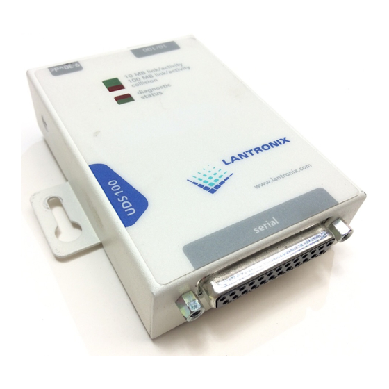
The UDS10 and UDS100 are single-port device servers that provide a quick, simple, and cost-effective way to bring the advantages of data accessibility and remote management to devices not currently connected to a network. The main difference between the two models is that the UDS100 provides both half and full duplex 10/100 Ethernet data transfer, whereas the UDS10 provides only half duplex 10Base-T Ethernet. -
Page 11: Figure 2-1. Application Examples
UDS10/UDS100 User Guide Introduction Figure 2-1. Application Examples Note: For step-by-step instructions on configuring the UDS for serial tunneling or for use with the Com Port Redirector, access the UDS Configuration Tutorials using Web Manager. (See Accessing Web Manager on page 18.) -
Page 12: Protocol Support
DeviceInstaller Web Manager: Through a web interface configures the UDS settings using the Lantronix Web Manager. (See Serial and Telnet Ports: There are two approaches to accessing Setup Mode: making a Telnet connection to the network port (9999) or connecting a terminal (or a PC running a terminal emulation program) to the unit’s serial port. -
Page 13: Product Information Label
Hardware address (also referred to as the Ethernet or MAC address) The first three bytes of the hardware address are fixed and read 00-20-4A, identifying the unit as a Lantronix product. The fourth, fifth, and sixth bytes are unique numbers assigned to each unit. -
Page 14: 3: Getting Started
This chapter describes how to get your UDS up and running in the shortest possible time. Installing the UDS Figure 3-1. UDS Connected to Serial Device and Network To install the unit, complete the following steps in order. Refer to the numbers in the figure above. -
Page 15: Required Information
UDS10/UDS100 User Guide Required Information Before configuring the UDS, have the following information available: Hardware Address Take note of the unit’s hardware address (also known as the Ethernet or MAC address). It is on the product label, in the format: 00-20-4a-XX-XX-XX, where the XXs are unique numbers assigned to the product (see page13). -
Page 16: Assigning The Ip Address And Related Network Settings
DeviceInstaller. Installing DeviceInstaller To use the DeviceInstaller utility, you first install it from the product CD. 1. Insert the product CD into your CD-ROM drive. The Lantronix UDS10/UDS100 DeviceInstaller window displays. 2. If the CD does not launch automatically: a) Click the Start button on the Task Bar and select Run. -
Page 17: Serial Port Login
UDS10/UDS100 User Guide Adding the Unit to the Manage List Now add the unit to the list of similar Lantronix devices on the network so that you can manage and configure it. To perform this step, click the Search icon. -
Page 18: 4: Configuring The Uds Using Web Manager
You must configure the UDS so that it can communicate on a network with your serial device. For example, you must set the way the unit responds to serial and network traffic, handles serial packets, and starts and closes connections. This chapter gives an overview of the procedure for using Web Manager to configure a UDS. -
Page 19: Figure 4-2. Uds Configuration Guidelines Page
Figure 4-2. UDS Configuration Guidelines Page UDS settings opens a configuration window to configure the UDS10/UDS100, as shown in Figure 4-3. Serial cabling lets you view pinouts for the UDS serial port. View UDS Configuration Tutorials provides step-by-step instructions for configuring serial tunneling and the Com Port Redirector. -
Page 20: Using Web Manager
For example, to enter server properties: 1. Click the Server Properties button. The Server Properties section of the Web page displays. 2. Confirm or enter values for IP Address Subnet Mask Gateway Address Figure 4-3. Lantronix Web Manager UDS10/UDS100 User Guide 5: Configuring... -
Page 21: Figure 4-4. Server Properties Configuration On The Web Browser
UDS10/UDS100 User Guide Figure 4-4. Server Properties Configuration on the Web Browser 3. In the Telnet Password field, enter a password to prevent unauthorized access to the Setup Mode using a Telnet connection to port 9999. The password is limited to 4 characters. (An enhanced password setting of 16 characters is available under Security Settings in Setup Mode.) -
Page 22: 5: Configuring The Uds Using Telnet Or The Serial Port
You must configure the UDS so that it can communicate on a network with your serial device. For example, you must set the way the unit will respond to serial and network traffic, how it will handle serial packets, and when to start or close a connection. As an alternative to using Web Manager, configure the UDS using a series of prompts referred to as Setup Mode, accessed using a Telnet or a serial port connection. -
Page 23: Using The Serial Port
UDS10/UDS100 User Guide 3. Select an option on the Change Setup menu by entering the number of the option in the Your choice ? prompt and pressing Enter. 4. To enter a value for a parameter, type the value and press Enter. To confirm a current value, just press Enter. -
Page 24: Server Configuration (Network Configuration)
A netmask defines the number of bits taken from the IP address that are assigned for the host section. The host section is the part of the IP address that is specific to the UDS. Figure 5-3. Network Configuration UDS10/UDS100 User Guide for more information about IP... -
Page 25: Change Telnet Configuration Password
UDS10/UDS100 User Guide Note: Class A: 24 bits; Class B: 16 bits; Class C: 8 bits. The unit prompts for the number of host bits to enter, then calculates the netmask, which displays in standard decimal-dot notation when the saved parameters display (for example, 255.255.255.0). -
Page 26: Channel 1 Configuration (Serial Port Settings)
The Interface (I/F) Mode is a bit-coded byte that you enter in hexadecimal notation. To look up hex values, see Note: communications. Current values display in parentheses. The Figure 5-5. Channel 1 Configuration B: Binary to Hexadecimal. UDS10/UDS100 User Guide B: Binary to... -
Page 27: Flow
UDS10/UDS100 User Guide The following table displays available I/F Mode options: I/F Mode Option Bit 7 6 5 4 3 2 1 0 RS-232C RS-422/485 RS-485 2-wire 7 Bit 8 Bit No Parity Even Parity Odd Parity 1 Stop bit... -
Page 28: Connect Mode
Reserved (well known ports) Telnet setup Reserved (77FEh) B: Binary to Hexadecimal. Table 5-6. Connect Mode Options UDS10/UDS100 User Guide Bit 7 6 5 4 3 2 1 0 0 0 0 0 1 0 1 1 0 0 0 0 0... -
Page 29: Manual Connection
Datagram Type: When selecting this option, you will be prompted for the datagram type. Enter 01 for directed or broadcast UDP. Hostlist: If you enable this option, the Lantronix unit scrolls through the hostlist until it connects to a device listed in the hostlist table. Once it connects, the unit stops trying to connect to any others. -
Page 30: Figure 5-6. Hostlist Option
3. After completing the hostlist, repeat the previous step if necessary to edit the hostlist again. 4. For Retrycounter, enter the number of times the Lantronix unit should try to make a good network connection to a hostlist entry that it has successfully ARPed. - Page 31 UDS10/UDS100 User Guide accumulating phone charges for each connection. Modem Mode allows you to replace modems with UDS units, and to use an Ethernet connection instead of a phone call. By not having to change communications applications, you avoid potentially expensive phone calls.
-
Page 32: Remote Ip Address
Enables or disables character echo and responses: n=0 disables character echo and responses. n=1 enables character echo and responses. Enables 1-character response or full verbose: n=0 enables 1-character response. n=1 enables full verbose. UDS10/UDS100 User Guide... -
Page 33: Disconnect Mode
UDS10/UDS100 User Guide Disconnect Mode This option determines the conditions under which the unit causes a network connection to terminate. In DisConnMode, DTR drop either drops the connection or is ignored. To look up hex values, see Note: Disconnect Mode Option... -
Page 34: Pack Control
Note: A transmission might occur if status information needs to be exchanged or an acknowledgment needs to be sent. B: Binary to Hexadecimal. Table 5-11. Pack Control Options Bit 7 6 5 4 3 2 1 0 UDS10/UDS100 User Guide... -
Page 35: Disconnect Time (Inactivity Timeout)
UDS10/UDS100 User Guide Configuring the UDS Using Telnet or the Serial Port Disconnect Time (Inactivity Timeout) Use Disconnect Time to set an inactivity timeout. The unit drops the connection if there is no activity on the serial line before the set time expires. Enter time in the following format: mm:ss, where m is the number of minutes and s is the number of seconds. -
Page 36: Tcp Keepalive Time In S
Configuring the UDS Using Telnet or the Serial Port UDS10/UDS100 User Guide TCP Keepalive time in s This option defines how many seconds the unit waits during a silent connection before checking to see whether the currently connected network device is still on the network. -
Page 37: Snmp Community Name
UDS10/UDS100 User Guide SNMP Community Name This option changes the SNMP community name on the unit. This allows for ease of management, and possibly some security. If someone tries to violate security but does not know what community to connect to, that person is unable to obtain the SNMP community information from the unit. -
Page 38: Factory Default Settings
To save all changes and reboot, select 9. All values are stored in nonvolatile memory. To exit the configuration mode without saving changes or rebooting, select 8. UDS10/UDS100 User Guide 9600 4C (1 stop bit, no parity, 8 bit, RS-232C) 10001 C0 (always accept incoming connection;... -
Page 39: 6: Updating Firmware
DeviceInstaller (the preferred way), TFTP, another unit, or the serial port. Another option is to use the unit's internal web interface (CBXW*.COB) using TFTP or DeviceInstaller. Following are typical names for the files. Check the Lantronix Web site for the latest versions and release notes. UDS10 LTX*.ROM (Network) -
Page 40: Using Tftp
To download new firmware using a TFTP client: 1. Use a TFTP client to send a binary file (LTX*.ROM for UDS10, DLX*.ROM for UDS100) to the unit to upgrade the unit's internal operational code, and CBXW*.cob to upgrade its internal web interface). -
Page 41: Using Another Unit
UDS10/UDS100 User Guide The unit performs a power reset after the firmware has been loaded and stored. Using Another Unit To distribute firmware to another unit over the network: 1. Enter the host unit's Monitor Mode (see 2. Send the firmware to the receiving unit using the SF command, where x.x.x.x is the receiving unit's IP address. -
Page 42: Figure 6-3. Firmware Upgrade Screen Display
2. Download the firmware to the unit using the DL command. 3. Select Send Text File and select the LTX*.HEX file for the UDS10 or DLX*.HEX file for the UDS100 to be downloaded. The downloaded file must be the .HEX (ASCII) version. -
Page 43: 7: Using Monitor Mode
Monitor Mode is a command line interface used for diagnostic purposes. There are two ways to enter Monitor Mode: locally using the serial port or remotely using the network. Entering Monitor Mode Using the Serial Port To enter Monitor Mode locally, follow the same principles used in setting the serial configuration settings: 1. -
Page 44: Using Monitor Mode Commands
Gets a memory page of configuration information from the device. Sets a memory page of configuration information on the device. Table 7-2. Command Response Codes OK; no error No answer from remote device Cannot reach remote device or no answer Wrong parameter(s) Invalid command UDS10/UDS100 User Guide... -
Page 45: 8: Troubleshooting And Contact Information
This chapter discusses how you can diagnose and fix errors quickly without having to contact a dealer or Lantronix. It helps to connect a terminal to the serial port while diagnosing an error so you can view summary messages that may display. When troubleshooting, always ensure that the physical connections (power cable, network cable, and serial cable) are secure. -
Page 46: Problems And Error Messages
Press Enter to go into Setup Mode displays. However, nothing happens when you press Enter, or your connection closes. Table 8-1. UDS10/UDS100 LEDs Meaning Valid 10 Mbps network connection Network packets transmitting and receiving Valid 100 Mbps network connection... - Page 47 Try plugging the UDS into another outlet. If this does not fix the problem, contact your dealer or Lantronix Technical Support for a replacement. Consult the LEDs section above or the Quick Start for the LED flashing sequence patterns.
- Page 48 The file you are attempting to load is the incorrect firmware file for the UDS. UDS10/UDS100 User Guide Solution Make sure that you are using the correct serial cable. The UDS serial port is just like a modem serial port (DCE).
-
Page 49: Technical Support
Technical Support If you are experiencing an error that is not described in this chapter, or if you are unable to fix the error, you may: Check our online knowledge base at http://www.lantronix.com/support Call us at: (800) 422-7044 Domestic (949) 453-7198 International... - Page 50 Troubleshooting and Contact Information UDS10/UDS100 User Guide When you report a problem, please provide the following information: Your name, and your company name, address, and phone number Lantronix UDS model number Lantronix UDS serial number Software version (on the first screen shown when you Telnet to port 9999)
-
Page 51: 9: Connections And Pinouts
Serial Port The UDS has a female DCE DB25 serial port that supports RS-232 and RS-485/422 serial standards (software selectable) up to 115 Kbps. Figure 9-1. Serial Interface Serial Connector Pinouts The unit’s female DB25 connector provides an RS-232C, RS-485, or RS-422 DCE serial port. -
Page 52: Figure 9-2. Db25 Female Dce Interface Rs232
Connections and Pinouts UDS10/UDS100 User Guide Figure 9-2. DB25 Female DCE Interface RS232 Figure 9-3. DB25 Female DCE Interface RS485/422... -
Page 53: Null-Modem Cable
When attaching the DB9 of the UDS to the DB9 com port on a PC, use a null-modem cable (Lantronix Part No. 500-163). The figure below shows the pinouts for a DB9 to DB9 null-modem cable. To configure the UDS using the DB9 serial port, you only need to pinout the TXD, RXD, and GND signals. -
Page 54: Ethernet Connector Pinouts
Connections and Pinouts UDS10/UDS100 User Guide Ethernet Connector Pinouts The UDS10 supports 10 Mbps half-duplex Ethernet through an RJ45 connector. The UDS100 supports 100 Mbps half or full duplex Ethernet through an RJ45 connector. Figure 9-6. RJ45 Ethernet Connector... -
Page 55: 10: Technical Specifications
UDS10 Technical Specifications x86 CPU, 25MHz clock, 128kByte RAM CPU, Memory Female DB25 connector (DCE pinout) Serial Interface Speed software selectable (300 to 115 kBaud) Software selectable RS-232C or RS-422/485 Network Interface 10 Mbps RJ45 Ethernet External adapter included Power Supply... -
Page 56: Uds100 Technical Specifications
Technical Specifications UDS100 Technical Specifications CPU, Memory Lantronix DSTni-LX 186 CPU, 48 MHz 1 MByte FLASH ROM 256 Kbytes zero wait state RAM Serial Interface Female DB25 connector (DCE pinout) Speed software selectable (300 to 115 kBaud) Software selectable RS-232C or RS-422/485... -
Page 57: A: Alternative Ways To Assign An Ip Address
Earlier chapters describe how to assign a static IP address using DeviceInstaller, Web Manager, and Setup Mode (through a Telnet or serial connection). This section covers other methods for assigning an IP address over the network. DHCP The unit ships with a default IP address of 0.0.0.0, which automatically enables DHCP. -
Page 58: Bootp
The IP address you just set is temporary and reverts to the default value when the unit’s power is reset, unless you configure the unit with a static IP address and store the changes permanently. arp -s 191.12.3.77 00:20:4a:xx:xx:xx arp -s 191.12.3.77 00-20-4a-xx-xx-xx telnet 191.12.3.77 1 telnet 191.12.3.77 9999 UDS10/UDS100 User Guide... -
Page 59: B: Binary To Hexadecimal Conversions
Many of the unit’s configuration procedures require you to assemble a series of options (represented as bits) into a complete command (represented as a byte). The resulting binary value must be converted to a hexadecimal representation. Use this chapter to learn how to convert binary values to hexadecimals or to look up values in the tables of configuration options in hexadecimal notation. -
Page 60: Scientific Calculator
Binary to Hexadecimal Conversions UDS10/UDS100 User Guide Scientific Calculator Another simple way to convert binary to hexadecimals is to use a scientific calculator, such as the one available on Windows’ operating systems. For example: 1. On the Windows’ Start menu, click Programs Accessories Calculator. -
Page 61: Connect Mode Options
UDS10/UDS100 User Guide Connect Mode Options Note: Character response codes are C=conn, D=disconn, N=unreachable Connect Mode Options Accept Incoming Connections Never Never Never Never Never Never Never Never Never Never Never Never Never Never With DTR With DTR With DTR... - Page 62 None (quiet) Character No active startup Hostlist Character Any character Character Active DTR Character CR (0x0D) Character Manual connection Character Autostart Character UDS10/UDS100 User Guide Hostlist Hostlist Hostlist Hostlist Hostlist Hostlist Hostlist Hostlist Hostlist Hostlist Hostlist Hostlist Hostlist Hostlist Hostlist...
- Page 63 UDS10/UDS100 User Guide Connect Mode Options Accept Incoming Connections Unconditionally Unconditionally Unconditionally Unconditionally Unconditionally Unconditionally Unconditionally Unconditionally Unconditionally Unconditionally Unconditionally Unconditionally Unconditionally Unconditionally The following connect mode options are for when you use modem emulation: Connect Mode Options for Modem Emulation...
-
Page 64: Disconnect Mode Options
Enable Enable Enable Enable Enable Enable Enable Enable Disable Enable Disable Disable Enable Disable Disable Enable Disable Disable UDS10/UDS100 User Guide Disconnect with EOT (^D) Enable Enable Enable Enable Enable Enable Enable Enable Enable Enable Enable Enable Enable Enable Enable... - Page 65 UDS10/UDS100 User Guide Disconnect Mode Options Disconnect Telnet Mode with DTR Drop Terminal Type Setup Enable Enable Enable Enable Enable Enable Enable Enable Enable Enable Enable Enable Enable Enable Enable Enable Enable Enable Enable Enable Enable Enable Enable Enable Enable...
-
Page 66: Flush Mode Options
Passive connection Active connection Passive connection Disconnect Active connection Disconnect Passive connection Disconnect Active connection Passive connection Disconnect Active connection Passive connection UDS10/UDS100 User Guide Network to Serial Alternate Packing Clear output buffer Algorithm upon: Enable Enable Enable Enable Enable Enable... - Page 67 UDS10/UDS100 User Guide Flush Mode Options Serial to Network Clear input buffer upon: Active connection Passive connection Disconnect Active connection Disconnect Passive connection Disconnect Active connection Passive connection Disconnect Active connection Passive connection Active connection Passive connection Disconnect Active connection...
- Page 68 Disconnect Active connection Passive connection Disconnect Active connection Passive connection Active connection Passive connection Disconnect Active connection Disconnect UDS10/UDS100 User Guide Network to Serial Alternate Packing Clear output buffer Algorithm upon: Active connection Passive connection Active connection Passive connection Active connection...
- Page 69 UDS10/UDS100 User Guide Flush Mode Options Serial to Network Clear input buffer upon: Passive connection Disconnect Active connection Passive connection Disconnect Active connection Passive connection Active connection Passive connection Disconnect Active connection Disconnect Passive connection Disconnect Active connection Passive connection...
- Page 70 Active connection Passive connection Disconnect Active connection Passive connection Active connection Passive connection Disconnect Active connection Disconnect Passive connection Disconnect UDS10/UDS100 User Guide Network to Serial Alternate Packing Clear output buffer Algorithm upon: Passive connection Disconnect Passive connection Disconnect Passive connection...
- Page 71 UDS10/UDS100 User Guide Flush Mode Options Serial to Network Clear input buffer upon: Active connection Passive connection Disconnect Active connection Passive connection Active connection Passive connection Disconnect Active connection Disconnect Passive connection Disconnect Active connection Passive connection Disconnect Binary to Hexadecimal Conversions...
-
Page 72: Interface Mode Options
RS-422/485 2-Wire RS-422/485 2-Wire RS-422/485 2-Wire RS-422/485 2-Wire RS-422/485 2-Wire RS-422/485 2-Wire RS-422/485 2-Wire RS-422/485 2-Wire RS-422/485 2-Wire RS-422/485 2-Wire RS-422/485 2-Wire RS-422/485 2-Wire UDS10/UDS100 User Guide Bits Parity Stop Bits Even Even Even Even Even Even Even Even Even... -
Page 73: Pack Control Options
UDS10/UDS100 User Guide Pack Control Options Pack Control Options Sendcharacter Defined by a: 1-Byte Sequence 1-Byte Sequence 1-Byte Sequence 1-Byte Sequence 1-Byte Sequence 1-Byte Sequence 1-Byte Sequence 1-Byte Sequence 1-Byte Sequence 1-Byte Sequence 1-Byte Sequence 1-Byte Sequence 2-Byte Sequence 2-Byte Sequence... - Page 74 2-Byte Sequence 2-Byte Sequence 2-Byte Sequence 2-Byte Sequence 2-Byte Sequence 2-Byte Sequence 2-Byte Sequence 2-Byte Sequence 2-Byte Sequence Trailing Idle Time Send Characters Force Immediately Transmit: after Sendcharacter 5sec 12ms 52ms 250ms 5sec 12ms 52ms 250ms 5sec UDS10/UDS100 User Guide...
-
Page 75: Declaration Of Conformity
Declaration of Conformity (according to ISO/IEC Guide 22 and EN 45014) Manufacturer’s Name & Address: Lantronix 15353 Barranca Parkway, Irvine, CA 92618 USA Declares that the following product: Product Name Conforms to the following standards or other normative documents: Safety: EN60950:1992+A1, A2, A3, A4, A11... -
Page 76: Warranty
-- repair or replace the product and return it to the customer freight prepaid. If the product is not under warranty, the customer may have Lantronix repair the unit on a fee basis or return it. No services are handled at the customer's site under this warranty. -
Page 77: Index
Index Application examples, 10 ARP and Telnet, 58 ARPCache timeout, 36 AutoIP, 15, 57 Baudrate, 26 Binary to hexadecimal conversions, 59 BOOTP, 15, 58 Buffer flushing, 33 Cable, 53 Com Port Redirector tutorial, 19 Compliance, 75 Connect Mode, 28 Connectors, 51 DB9 to DB9 null-modem cable, 53 Defaults List, 38... - Page 78 Disabling Telnet access, 37 using, 23 SNMP Changing community name, 37 Disabling, 36 Subnet mask Assigning on Web Manager, 20 TCP Keepalive time, 36 UDS10/UDS100 User Guide Technical specifications UDS10, 55 UDS100, 56 Technical Support, 49 Telnet Configuration password, 25 Password, 20...
Need help?
Do you have a question about the UDS10 and is the answer not in the manual?
Questions and answers