Allied Telesis AT-FS708 Installation Manual
Fast ethernet
switch
Hide thumbs
Also See for AT-FS708:
- Installation manual (61 pages) ,
- Datasheet (2 pages) ,
- Installation manual (48 pages)
Table of Contents
Advertisement
Quick Links
Download this manual
See also:
Installation Manual
Advertisement
Table of Contents

Subscribe to Our Youtube Channel
Related Manuals for Allied Telesis AT-FS708


Summary of Contents for Allied Telesis AT-FS708
-
Page 1: Installation Guide
Fast Ethernet Switch AT-FS708 Installation Guide 613-001268 Rev. A... - Page 2 Allied Telesis, Inc. reserves the right to make changes in specifications and other information contained in this document without prior written notice. The information provided herein is subject to change without notice. In no event shall Allied Telesis, Inc. be liable for any incidental, special, indirect, or consequential damages whatsoever, including but not limited to lost profits, arising out of or related to this manual or the information contained herein, even if Allied Telesis, Inc.
- Page 3 Electrical Safety and Emissions Standards This product meets the following standards. U.S. Federal Communications Commission Declaration of Conformity Manufacturer Name: Allied Telesis, Inc. Declares that the product: Fast Ethernet Switch Model Number: AT-FS708 This product complies with FCC Part 15B, Class B Limits: This device complies with part 15 of the FCC Rules.
- Page 4 Translated Safety Statements Important: The indicates that a translation of the safety statement is available in a PDF document titled “Translated Safety Statements” on our web site. Go to http://www.alliedtelesis.com/support/software/. Select Switches under Product Category and this product under Product Name. You can view this document online or download it onto a local workstation or server.
-
Page 5: Table Of Contents
Contents Preface ....................................6 Safety Symbols Used in this Document..........................7 Where to Find Web-based Guides ............................8 Contacting Allied Telesis ................................9 Online Support ................................9 Email and Telephone Support ............................9 Warranty ..................................9 Returning Products................................9 Sales or Corporate Information ............................9 Management Software Updates ............................9 Chapter 1: Product Description ............................10... -
Page 6: Preface
Preface This guide contains instructions on how to install the AT-FS708 Fast Ethernet switch. This preface contains the following sections: “Safety Symbols Used in this Document” on page 7 “Where to Find Web-based Guides” on page 8 “Contacting Allied Telesis” on page 9... -
Page 7: Safety Symbols Used In This Document
AT-FS708 Fast Ethernet Switch Installation Guide Safety Symbols Used in this Document This document uses the safety symbols defined in Table 1. Table 1. Safety Symbols Symbol Meaning Description Caution Performing or omitting a specific action may result in equipment damage or loss of data. -
Page 8: Where To Find Web-Based Guides
Preface Where to Find Web-based Guides The installation and user guides for all Allied Telesis products are available in portable document format (PDF) on our web site. Go to http://www.alliedtelesis.com/support/software/. Select Switches under Product Category and the this product under Product Name. You can view... -
Page 9: Contacting Allied Telesis
Allied Telesis web site: www.alliedtelesis.com Allied Telesis FTP server: ftp://ftp.alliedtelesis.com If you prefer to download new software from the Allied Telesis FTP server from your workstation’s command prompt, you will need FTP client software and you must log in to the server. Enter “anonymous” for the user... -
Page 10: Chapter 1: Product Description
Chapter 1 Product Description This chapter contains the follows sections: “Overview” on page 11 “Key Features” on page 12 “Hardware Feature Description” on page 13 “A Few Ethernet Switching Basics” on page 16... -
Page 11: Overview
Figure 2 illustrates the back panel of the AT-FS708 switch. 100-240VAC~ 50-60Hz Figure 2. AT-FS708 Back Panel The AT-FS708 switch can be used on a desktop, or mounted to a wall or in a rack. The switch is easy to install and does not require software configuration or management. -
Page 12: Key Features
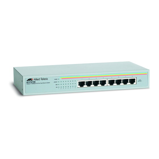
Chapter 1: Product Description Key Features The AT-FS708 switch has the following key features: Eight 10/100 Mbps (10Base-T / 100Base-TX) twisted pair ports with RJ-45 connectors System and port LEDs Auto-Negotiate and Auto MDI/MDI-X on all 10/100 Mbps twisted pair... -
Page 13: Hardware Feature Description
AT-FS708 Fast Ethernet Switch Installation Guide Hardware Feature Description The sections below describe the hardware features of the AT-FS708 Fast Ethernet switch: “10/100Base-TX Twisted Pair Ports,” next “System and Port LEDs” on page 14 “ECOFriendly Push Button” on page 15 “AC Power Connector”... -
Page 14: System And Port Leds
Consequently, you can use a straight-through twisted pair cable to connect any network device to a port. System and Port The system and port LEDs on the front panel of the AT-FS708 switch display status information. Each port has three LEDs. Table 2 describes LEDs the system and port LEDs on the AT-FS708 Fast Ethernet switch. -
Page 15: Ecofriendly Push Button
Note The power LED remains active at all times. AC Power The AT-FS708 Fast Ethernet switch has a single AC power supply socket on the back panel. Refer to Appendix A, “Technical Specifications” on Connector page 33, for the input voltage range. -
Page 16: A Few Ethernet Switching Basics
NIC already has a MAC address assigned to it by its manufacturer. The AT-FS708 Fast Ethernet switch can contain up to 1,024 entries in its MAC address table. The switch uses the table to store the MAC addresses of the network end-nodes connected to the ports, along with the port number on which each address was learned. -
Page 17: Duplex Mode
The twisted pair ports on the AT-FS708 switch can operate in half- or full- duplex mode for 10/100 Mbps. They are IEEE 802.3u-compliant and use Auto-Negotiation to set the duplex mode setting for you automatically. - Page 18 Chapter 1: Product Description A port operating in full-duplex mode uses PAUSE frames, as specified in the IEEE 802.3x standard, to stop the transmission of data from an end- node. Whenever the switch wants an end-node to stop transmitting data, it issues this frame.
-
Page 19: Chapter 2: Installation
Chapter 2 Installation This chapter contains the following sections: “Reviewing Safety Precautions” on page 20 “Selecting a Site for the Switch” on page 22 “Planning the Installation” on page 23 “Unpacking the Switch” on page 24 “Installing the Switch on a Table or Desktop” on page 25 “Wall-Mounting the Switch”... -
Page 20: Reviewing Safety Precautions
Chapter 2: Installation Reviewing Safety Precautions Please review the following safety precautions before you begin to install the switch. Note Important: The indicates that a translation of the safety statement is available in a PDF document titled “Translated Safety Statements” on our web site. Go to http://www.alliedtelesis.com/support/software/. - Page 21 AT-FS708 Fast Ethernet Switch Installation Guide All Countries: Install product in accordance with local and National Electrical Codes. Warning: As a safety precaution, install a circuit breaker with a minimum value of 15 Amps between the equipment and the DC power source.
-
Page 22: Selecting A Site For The Switch
Selecting a Site for the Switch Observe the following requirements when choosing a site for the AT-FS708 Fast Ethernet switch: If you plan to install the switch in an equipment rack, be sure that the rack is safely secured and that it will not tip over. Devices in a rack should be installed starting at the bottom, with the heavier devices near the bottom of the rack. -
Page 23: Planning The Installation
AT-FS708 Fast Ethernet Switch Installation Guide Planning the Installation Table 3 contains the cabling specifications for the twisted pair ports. Table 3. Twisted Pair Cabling and Distances Maximum Speed Type of Cable Operating Distance 10 Mbps Category 3 or better 100-ohm... -
Page 24: Unpacking The Switch
Chapter 2: Installation Unpacking the Switch To unpack an AT-FS708 switch, perform the following procedure: 1. Remove all components from the shipping package. Note Store the packaging material in a safe location. You must use the original shipping material if you need to return the unit to Allied Telesis. -
Page 25: Installing The Switch On A Table Or Desktop
AT-FS708 Fast Ethernet Switch Installation Guide Installing the Switch on a Table or Desktop To install the switch on a table or desktop, perform the following procedure: 1. Remove all the items from the packaging and store the packaging material in a safe place. In the event a problem occurs and you need to return the unit, please use as much of the original shipping material as possible. -
Page 26: Wall-Mounting The Switch
The plastic anchors used for wall mounting the switch are intended for installation in walls made of sheetrock or concrete materials. To mount an AT-FS708 switch onto a wall, perform the following procedure: 1. Remove all equipment from the package and store the packaging material in a safe place. - Page 27 Figure 5. 1777 Figure 5. Aligning an AT-FS708 for Wallmount Installation 8. Make sure that the switch is securely mounted onto the wall. 9. Proceed to “Cabling the Switch” on page 30 for the cable installation.
-
Page 28: Installing The Switch In A Rack
Chapter 2: Installation Installing the Switch in a Rack Perform the following procedure to install the switch in a standard 19-inch rack. 1. If attached, remove the rubber feet, data cables, and power cord from the switch. 2. Attach the two mounting brackets (provided) to the sides of the switch using the bracket mounting screws (provided), as shown in Figure 6. - Page 29 AT-FS708 Fast Ethernet Switch Installation Guide 3. Mount the switch in a 19-inch rack using rack mounting screws (not provided), as shown in Figure 7. A T - F S 7 0 1 0 B a se F a st...
-
Page 30: Cabling The Switch
Chapter 2: Installation Cabling the Switch To connect the twisted pair cables to the ports on the AT-FS708 switch, perform the following procedure: 1. Connect the twisted pair data cables to the RJ-45 ports on the switch, as shown in Figure 8. -
Page 31: Powering On The Switch
AT-FS708 Fast Ethernet Switch Installation Guide Powering On the Switch To apply power to the AT-FS708 switch without the optional power cord retaining clip installed, perform the following procedure: 1. Apply AC power to the switch by plugging the power cord into the AC power connector on the back panel of the unit, as shown in Figure 9. -
Page 32: Chapter 3: Troubleshooting
If you are still unable to resolve the problem after following the instructions in this chapter, contact Allied Telesis Technical Support for assistance. Refer to “Contacting Allied Telesis” on page 9. Check the POWER LED on the front of the switch. If the LED is OFF,... -
Page 33: Appendix A: Technical Specifications
Appendix A Technical Specifications Physical Specifications Dimensions: (W x D x H) 250 mm x 117 mm x 36.5 mm (9.84 in x 4.60 in x 1.44 in) Weight: 0.75 kg (1.65 lbs) Environmental Specifications Operating Temperature: 0° C to 40° C (32° F to 104° F) Storage Temperature: -25°... -
Page 34: Safety And Electromagnetic Emissions Certifications
Appendix A: Technical Specifications Safety and Electromagnetic Emissions Certifications FCC Part 15 Class B, CISPR 22 Class B, EN55022 Class B, Immunity EN55024 Electrical Safety UL 60950 ( ), EN60950 (TUV), C-Tick, CE Mark... -
Page 35: Rj-45 Twisted Pair Port Connectors
RJ-45 Twisted Pair Port Connectors This section lists the connectors and connector pinouts for the AT-FS708 Fast Ethernet switch and its components. Figure 10 illustrates the pin layout to an RJ-45 connector and port. Figure 10. RJ-45 Connector and Port Pin Layout Table 4 lists the RJ-45 pin signals when a twisted pair port is operating in the MDI configuration.
Need help?
Do you have a question about the AT-FS708 and is the answer not in the manual?
Questions and answers