Allied Telesis AT-2916T Installation Manual
Gigabit ethernet network
adapters
Hide thumbs
Also See for AT-2916T:
- Datasheet (2 pages) ,
- Installation manual (142 pages) ,
- Installation manual (126 pages)

Related Manuals for Allied Telesis AT-2916T


Summary of Contents for Allied Telesis AT-2916T
-
Page 1: Installation Guide
Gigabit Ethernet Network Adapters AT-2916T AT-2971SX AT-2971T Installation Guide 613-000767 Rev. A... - Page 2 Telesis, Inc. be liable for any incidental, special, indirect, or consequential damages whatsoever, including but not limited to lost profits, arising out of or related to this manual or the information contained herein, even if Allied Telesis, Inc. has been...
- Page 3 European Union Restriction of the Use of Certain Hazardous Substances (RoHS) in Electrical and Electronic Equipment This Allied Telesis RoHS-compliant product conforms to the European Union Restriction of the Use of Certain Hazardous Substances (RoHS) in Electrical and Electronic Equipment. Allied Telesis ensures RoHS conformance by requiring supplier Declarations of Conformity, monitoring incoming materials, and maintaining manufacturing process controls.
- Page 4 Electrical Safety EN60950 (TUV), UL 60950 ( Laser Safety EN60825 Translated Safety Statements Important: The indicates that a translation of the safety statement is available in a PDF document titled “Translated Safety Statements” (613-000405) on the Allied Telesis website at www.alliedtelesis.com.
-
Page 5: Table Of Contents
Contents Preface ....................................9 Safety Symbols Used in this Document..........................10 Where to Find Web-based Guides ............................11 Contacting Allied Telesis ..............................12 Online Support ................................12 Email and Telephone Support ............................12 Warranty ..................................12 Returning Products................................12 Sales or Corporate Information .............................12 Management Software Updates ............................12 Chapter 1: Introduction to the AT-29xx Series Gigabit Ethernet Network Adapters ...........13... - Page 6 Contents...
- Page 7 Figures Figure 1. AT-2916T Gigabit Ethernet Adapter ........................16 Figure 2. AT-2971SX Gigabit Ethernet Adapter ........................17 Figure 3. AT-2971T Gigabit Ethernet Adapter ........................18 Figure 4. Removing the PC Cover............................25 Figure 5. Removing the Faceplate From PCI Slot .......................26 Figure 6. Inserting the Network Adapter Card ........................27...
- Page 8 Figures...
-
Page 9: Preface
This guide contains instructions on how to install the AT-29xx Series Gigabit Ethernet network adapters. The Preface contains the following sections: “Safety Symbols Used in this Document” on page 10 “Where to Find Web-based Guides” on page 11 “Contacting Allied Telesis” on page 12... -
Page 10: Safety Symbols Used In This Document
Preface Safety Symbols Used in this Document This document uses the safety symbols defined in Table 1. Table 1. Safety Symbols Symbol Meaning Description Caution Performing or omitting a specific action may result in equipment damage or loss of data. Warning Performing or omitting a specific action may result in electrical shock. -
Page 11: Where To Find Web-Based Guides
AT-29xx Series Gigabit Ethernet Network Adapters Installation Guide Where to Find Web-based Guides The installation and user guides for all Allied Telesis products are available in portable document format (PDF) on our web site at www.alliedtelesis.com. You can view the documents online or download... -
Page 12: Contacting Allied Telesis
Allied Telesis web site: www.alliedtelesis.com Allied Telesis FTP server: ftp://ftp.alliedtelesis.com If you prefer to download new software from the Allied Telesis FTP server from your workstation’s command prompt, you will need FTP client software and you must log in to the server. Enter “anonymous” for the user... -
Page 13: Chapter 1: Introduction To The At-29Xx Series Gigabit Ethernet Network Adapters
Chapter 1 Introduction to the AT-29xx Series Gigabit Ethernet Network Adapters This chapter provides an introduction to the Allied Telesis AT-29xx Series Gigabit Ethernet network adapters and contains the following sections: “Functional Description” on page 14 “Features” on page 15... -
Page 14: Functional Description
The AT-29xxSX Series of Gigabit Ethernet adapters includes the following models: AT-2916T AT-2971SX AT-2971T The AT-2916T adapter is a 33/66Mhz 32-bit interface (PCI) card. The AT-2971SX and AT-2971T adapters are 33-133Mhz 32-bit and 64-bit interface (PCI) cards. Contents of Your Included with your adapter are the following items:... -
Page 15: Features
AT-29xx Series Gigabit Ethernet Adapters Installation Guide Features Following is a list of the AT-29xx Series Gigabit Ethernet network adapters features for all of the supported operating systems: TCP, UDP, and IP checksum calculation Jumbo frames (9 KB) TCP segmentation (large send off-load) PXE support Advanced power management/wake on LAN Flow Control (IEEE 802.3X) -
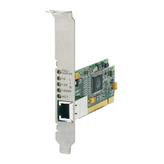
Page 16: Leds
Each adapter has a set of LEDs as shown in the following illustrations and tables: “AT-2916T,” next “AT-2971SX” on page 17 “AT-2971T” on page 18 AT-2916T The AT-2916T Gigabit Ethernet adapter has one copper port and five LEDs, as shown in Figure 1 and described in Table 1. FULL DUPLEX 1000 1250 Figure 1. -
Page 17: Figure 2. At-2971Sx Gigabit Ethernet Adapter
AT-29xx Series Gigabit Ethernet Adapters Installation Guide Table 1. AT-2916T LEDs (Continued) Color State Description Green A valid link has been established at 100 Mbps. No valid link at 100 Mbps. 1000 Green A valid link has been established at 1000 Mbps. -
Page 18: Figure 3. At-2971T Gigabit Ethernet Adapter
Chapter 1: Introduction to the AT-29xx Series Gigabit Ethernet Network Adapters Table 2. AT-2971SX LEDs Color State Description 1000/LINK Green A valid link has been established at 1000 Mbps. No valid link at 1000 Mbps. Green The adapter is receiving or transmitting data. - Page 19 AT-29xx Series Gigabit Ethernet Adapters Installation Guide Table 3. AT-2971T LEDs (Continued) Color State Description No valid link at 10 Mbps. Green A valid link has been established at 100 Mbps. No valid link at 100 Mbps. 1000 Green A valid link has been established at 1000 Mbps.
- Page 20 Chapter 1: Introduction to the AT-29xx Series Gigabit Ethernet Network Adapters...
-
Page 21: Chapter 2: Installing The Hardware
Chapter 2 Installing the Hardware This chapter contains the following sections: “Reviewing Safety Precautions” on page 22 “Pre-Installation Checklist” on page 24 “Installing a Network Adapter Card” on page 25 “Connecting the Network Cables” on page 29... -
Page 22: Reviewing Safety Precautions
Note indicates that a translation of the safety statement is available in a PDF document titled “Translated Safety Statements” (613-000405) on the Allied Telesis website at www.alliedtelesis.com. Warning This is a “Class 1 LED product”. Warning Do not stare into the laser beam. - Page 23 AT-29xx Series Gigabit Ethernet Adapters Installation Guide wrists. - Use only insulated or nonconducting tools. - Verify that the system is powered OFF and unplugged before accessing internal components. - Installation or removal of adapters must be performed in a static- free environment.
-
Page 24: Pre-Installation Checklist
6. Check the adapter for visible signs of damage, particularly on the card’s edge connector. Never attempt to install any damaged adapter. If the adapter is damaged, report it to Allied Telesis. See “Contacting Allied Telesis” on page 12. -
Page 25: Installing A Network Adapter Card
AT-29xx Series Gigabit Ethernet Adapters Installation Guide Installing a Network Adapter Card The following instructions apply to installing the Gigabit Ethernet adapter in most systems. Refer to the manuals that were supplied with your system for details about performing these tasks on your particular system. To install the network adapter card, perform the following procedure: 1. -
Page 26: Figure 5. Removing The Faceplate From Pci Slot
Chapter 2: Installing the Hardware 3. Select an empty, non-shared PCI slot and remove the faceplate. Keep the faceplate in a safe place. You may need it for future use. See Figure 5. Figure 5. Removing the Faceplate From PCI Slot Note If you cannot locate or know how to find an appropriate PCI slot, refer to the documentation that came with your system. -
Page 27: Figure 6. Inserting The Network Adapter Card
AT-29xx Series Gigabit Ethernet Adapters Installation Guide Make sure the card is securely seated. See Figure 6. Figure 6. Inserting the Network Adapter Card Note The connector dock in a 32-bit PCI slot is shorter than in a 64-bit PCI slot. -
Page 28: Figure 7. Securing The Adapter Card
Chapter 2: Installing the Hardware 6. Secure the network adapter card to the chassis with a Phillips-head screw (not provided) as shown in Figure 7. Figure 7. Securing the Adapter Card 7. Replace the system’s cover and secure it with the screws removed in Step 2. -
Page 29: Connecting The Network Cables
AT-29xx Series Gigabit Ethernet Adapters Installation Guide Connecting the Network Cables All the fiber Gigabit Ethernet network adapters have two fiber optic connectors for attaching the system to a compatible link partner, or an IEEE 802.3z compliant gigabit switch. After connecting the system to the network and power is supplied, the adapter performs auto-negotiation and attempts to establish the connection at 1000 Mbps full-duplex only. - Page 30 Chapter 2: Installing the Hardware...
-
Page 31: Appendix A: Specifications
Specifications Physical Specifications Dimensions: AT-2916T : 11.99 cm x 5.29 cm (4.72 in. x 2.08 in.) AT-2971T : 16.76 cm x 5.73 cm (6.6 in. x 2.26in.) AT-2971SX : 16.76 cm x 6.44 cm (6.6 in. x 2.54 in.) Weight: AT-2916T : 65 g (.14 lbs.) -
Page 32: Performance Specifications
Appendix A: Specifications Performance Specifications PCI clock: 33/66 MHz max PCI-X clock: 66 to 133 MHz PCI or PCI-X Data/Address: AT-2916T 32-bit AT-2971T 32-bit and 64-bit AT-2971SX 32-bit and 64-bit Operating Specifications Output Optical Power: -9.5 dBm minimum to -4 dBm maximum...
Need help?
Do you have a question about the AT-2916T and is the answer not in the manual?
Questions and answers