Table of Contents
Advertisement
Quick Links
Advertisement
Table of Contents

Related Manuals for Allied Telesis AT-FS717FC


Summary of Contents for Allied Telesis AT-FS717FC
- Page 1 Fast Ethernet Switch ® AT-FS717FC/SC Installation Guide PN 613-000560 Rev C...
- Page 2 Allied Telesis, Inc. has been advised of, known, or...
-
Page 3: Electrical Safety And Emissions Standards
Electrical Safety and Emissions Standards This product meets the following standards. U.S. Federal Communications Commission Declaration of Conformity Manufacturer Name: Allied Telesis, Inc. Declares that the product: Fast Ethernet Switch Model Number: AT-FS717FC/SC This product complies with FCC Part 15B, Class B Limits: This device complies with part 15 of the FCC Rules. - Page 4 Electrical Safety and Emissions Standards FCC Class B, CISPR 22 Class B, EN55022 Class B, C-TICK, CE Immunity EN55024 Electrical Safety UL 60950 ( ), EN60950 (TUV) Laser EN60825 This is a “Class 1 LED Product”.
- Page 5 AT-FS717FC/SC Fast Ethernet Switch Installation Guide Translated Safety Statements Important: Appendix B contains translated safety statements for installing this equipment. When you see the , go to Appendix B for the translated safety statement in your language. Wichtig: Anhang B enthält übersetzte Sicherheitshinweise für die Installation dieses Geräts. Wenn sehen, schlagen Sie in Anhang B den übersetzten Sicherheitshinweis in Ihrer Sprache nach.
-
Page 6: Table Of Contents
Installing the Switch on a Table or Desktop........................30 Installing the Switch in a Rack ............................32 Wall-Mounting the Switch ..............................33 Cabling an AT-FS717FC/SC Switch..........................35 Cabling a Twisted Pair Port ............................35 Cabling a Fiber Optic Port ............................36 Setting the Duplex Mode Manually ............................ 38 Powering On the Switch .............................. - Page 7 AT-FS717FC/SC Fast Ethernet Switch Installation Guide Appendix A Technical Specifications ..............................41 Physical Specifications ..............................41 Environmental Specifications............................. 41 Power Specifications ................................. 41 Safety and Electromagnetic Emissions Certifications......................42 Compliance Standards ..............................42 RJ-45 Twisted Pair Port Connectors ..........................43 SC Type Connector ................................
-
Page 8: Preface
Appendix A, ”Technical Specifications” on page 41 Appendix B, ”Translated Safety Statements” on page 45 This preface contains the following sections: “How This Guide is Organized” on page 8 “Document Conventions” on page 9 “Contacting Allied Telesis” on page 10... -
Page 9: Document Conventions
AT-FS717FC/SC Fast Ethernet Switch Installation Guide Document Conventions This document uses the following conventions to highlight important information: Note Notes provide additional information. Warning Warnings inform you that performing or omitting a specific action may result in bodily injury. Caution Cautions inform you that performing or omitting a specific action may result in equipment damage or loss of data. -
Page 10: Contacting Allied Telesis
Knowledge Base to submit questions to our technical support staff and review answers to previously asked questions. Email and For Technical Support via email or telephone, refer to the Allied Telesis web site: http://www.alliedtelesis.com. Select your country from the list Telephone displayed on the website. -
Page 11: Product Description
Chapter 1 Product Description This chapter contains the follows sections: “Overview” on page 12 “Key Features” on page 13 “Standards” on page 13 “Hardware Feature Description” on page 14 “A Few Ethernet Switching Basics” on page 18 “Network Topologies” on page 21... -
Page 12: Overview
The 100Base-FX fiber optic port feature one SC connector with a maximum distance of 2 kilometers (1.2 miles). Both type of ports on the AT-FS717FC/SC can operate in either half- or full-duplex mode. To set the duplex mode of the fiber optic port, access the duplex mode switch located in the front of the switch. -
Page 13: Key Features
AT-FS717FC/SC Fast Ethernet Switch Installation Guide The AT-FS717FC/SC switch can be used on a desktop or mounted on a wall. The switch is easy to install and does not require software configuration or management. Key Features The AT-FS717FC/SC switch has the following key features:... -
Page 14: Hardware Feature Description
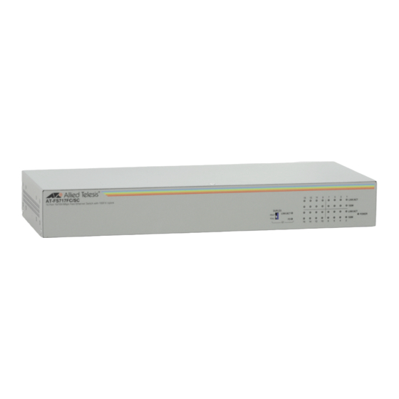
One duplex mode switch (for fiber optic port only) System and port LEDs AC power supply 10/100Base-TX The AT-FS717FC/SC Fast Ethernet switch features Sixteen twisted pair ports. The features of the twisted pair ports are explained in the following Twisted Pair sections. -
Page 15: 100Base-Fx Fiber Optic Port
100 Mbps. 100FX Duplex Mode Switch The AT-FS717FC/SC switch has one duplex mode switch for its fiber optic port, located on the front panel of the chassis. The fiber optic port on the switch can operate in either half- or full-duplex mode. -
Page 16: Leds
Multimode fiber is for short distances, typically no more than 2 kilometers (1.2 miles). Single- mode is for longer distances. The fiber optic port on the AT-FS717FC/SC switch has a maximum distance of 1 kilometers (1.2 miles), and is designed to be used with either 54/125 or 60/125 micron multi-mode cable. -
Page 17: Ac Power Connector
AT-FS717FC/SC Fast Ethernet Switch Installation Guide AC Power The AT-FS717FC/SC Fast Ethernet switch has a single AC power supply socket on the back panel, which has an auto-switch AC input. Refer to Connector Appendix A, “Technical Specifications” on page 41, for the input voltage specifications. -
Page 18: A Few Ethernet Switching Basics
NIC already has a MAC address assigned to it by its manufacturer. The AT-FS717FC/SC Fast Ethernet switch can contain up to 4K entries in its MAC address table. The switch uses the table to store the MAC addresses of the network end-nodes connected to the ports, along with the port number on which each address was learned. -
Page 19: Duplex Mode
The twisted pair ports on the AT-FS717FC/SC switch can operate in half- or full-duplex mode for 10/100 Mbps. They are IEEE 802.3u-compliant and use Auto-Negotiation to set the duplex mode setting for you automatically. - Page 20 Chapter 1: Product Description A port operating in full-duplex mode uses PAUSE frames, as specified in the IEEE 802.3x standard, to stop the transmission of data from an end- node. Whenever the switch wants an end-node to stop transmitting data, it issues this frame.
-
Page 21: Network Topologies
AT-FS717FC/SC Fast Ethernet Switch Installation Guide Network Topologies The AT-FS717FC/SC switch can be used in a variety of network topologies, such as a stand alone, Ethernet hub, and backbone. Each type of topologies is described below. Standalone Figure 3 illustrates the Standalone topology where each end-node is... -
Page 22: Ethernet Hub Topology
Chapter 1: Product Description Ethernet Hub Figure 4 illustrates the Ethernet Hub topology where four 10/100 Mbps Ethernet hubs are connected together using an AT-FS717FC/SC. With Topology this topology, the switch functions as a bridge between the different workgroups by controlling the flow of data between the workgroups. The... -
Page 23: Backbone Topology
2 kilometers (1.2 miles), the ports can be used to connect together switches that are physically apart. In the topology shown in Figure 5, one AT-FS717FC/SC, one AT-FS706EFC/SC, and one AT-FS709EFC/SC switches are interconnected using the fiber optic ports. -
Page 24: Invalid Loop Topology
Ethernet frames caught in repeating cycles can needlessly consume network bandwidth and ‘hang- up’ the entire network. An example of an invalid loop topology is shown in Figure 6. AT-FS706EFC/SC AT-FS717FC/SC AT-FS717FC/SC Ethernet Hub 1142 Figure 6. Invalid Loop Topology... -
Page 25: Chapter 2 Installation
“Installing the Switch on a Table or Desktop” on page 30 “Installing the Switch in a Rack” on page 32 “Wall-Mounting the Switch” on page 33 “Cabling an AT-FS717FC/SC Switch” on page 35 “Powering On the Switch” on page 39... -
Page 26: Reviewing Safety Precautions
Chapter 2: Installation Reviewing Safety Precautions Please review the following safety precautions before you begin to install the switch or any of its components. Refer to “Translated Safety Statements” on page 45 for translated safety statements in your language. Warning To prevent electric shock, do not remove the cover. -
Page 27: Selecting A Site For The Switch
AT-FS717FC/SC Fast Ethernet Switch Installation Guide Selecting a Site for the Switch Observe the following requirements when choosing a site for the AT-FS717FC/SC Fast Ethernet switch: If you plan to install the switch in an equipment rack, be sure that the rack is safely secured and that it will not tip over. -
Page 28: Planning The Installation
Chapter 2: Installation Planning the Installation Table 2 contains the cabling specifications for the twisted pair ports. Table 2. Twisted Pair Cabling and Distances Maximum Speed Type of Cable Operating Distance 10 Mbps Category 3 or better 100-ohm 100 m (328 ft) shielded or unshielded twisted pair cable 100 Mbps... -
Page 29: Unpacking The Switch
AT-FS717FC/SC Fast Ethernet Switch Installation Guide Unpacking the Switch To unpack an AT-FS717FC/SC switch, perform the following procedure: 1. Remove all components from the shipping package. Note Store the packaging material in a safe location. You must use the original shipping material if you need to return the unit to Allied Telesis. -
Page 30: Installing The Switch On A Table Or Desktop
Chapter 2: Installation Installing the Switch on a Table or Desktop To install the switch on a table or desktop, perform the following procedure: 1. Remove all the items from the packaging and store the packaging material in a safe place. In the event a problem occurs and you need to return the unit, please use as much of the original shipping material as possible. - Page 31 AT-FS717FC/SC Fast Ethernet Switch Installation Guide Warning Power cord is used as a disconnection device: To de-energize equipment, disconnect the power cord. 6. Verify that the POWER LED is green. If the LED is OFF, refer to “Installation” on page 25 for instructions.
-
Page 32: Installing The Switch In A Rack
Chapter 2: Installation Installing the Switch in a Rack Perform the following procedure to install the switch in a standard 19-inch rack. 1. If attached, remove the rubber feet, data cables, and power cord from the switch. 2. Attach the two mounting brackets (provided) to the sides of the switch using the bracketmounting screws (provided), as shown in Figure 8. -
Page 33: Wall-Mounting The Switch
The switch can be mounted horizontally on a wall using the two keyhole slots in the bottom of the switch. To mount an AT-FS717FC/SC switch onto a wall, perform the following procedure: 1. Remove all equipment from the package and store the packaging material in a safe place. - Page 34 7. Position and hang the switch onto the wall using the two keyhole slots located in the bottom of the switch, as illustrated in Figure 11. 1137 Figure 11. Wallmounting an AT-FS717FC/SC Switch 8. Make sure that the switch is securely mounted onto the wall. The switch is now ready for cabling.
-
Page 35: Cabling An At-Fs717Fc/Sc Switch
AT-FS717FC/SC Fast Ethernet Switch Installation Guide Cabling an AT-FS717FC/SC Switch Perform the following procedures to connect to the ports that come with the AT-FS717FS/SC switch. Cabling a When connecting a twisted pair cable to a port, observe the following guidelines: Twisted Pair Port An RJ-45 connector should fit snugly into the port on the switch. -
Page 36: Cabling A Fiber Optic Port
Chapter 2: Installation Cabling a Fiber When attaching a fiber optic cable, be sure to observe the following guidelines: Optic Port Be sure that the cable connector is firmly locked into place in the port. You should verify that you are using the appropriate type of fiber optic cabling. - Page 37 AT-FS717FC/SC Fast Ethernet Switch Installation Guide Cabling a Dual SC Connector To connect a fiber optic cable to a dual SC connector, perform the following procedure: Warning Class 1 laser product. Warning Do not stare into the laser beam. 1. Remove the dust cover from the fiber optic port, as shown in Figure 14.
-
Page 38: Setting The Duplex Mode Manually
Setting the Duplex Mode Manually To manually change the duplex mode of the fiber optic port on the AT-FS717FC/SC switch, perform the following procedure: 1. Locate the duplex mode switch on the front panel of the chassis. 2. Use the tip of a pen to manually change the duplex mode switch to half- or full-duplex mode, as shown in Figure 16. -
Page 39: Powering On The Switch
AT-FS717FC/SC Fast Ethernet Switch Installation Guide Powering On the Switch The switch is ready for network operations. To apply power to the AT-FS717FC/SC switch, perform the following procedure: 1. Apply AC power to the switch by plugging the power cord into the AC power connector on the back panel of the unit, as shown in Figure 17. -
Page 40: Chapter 3 Troubleshooting
If you are still unable to resolve the problem after following the instructions in this chapter, contact Allied Telesis Technical Support for assistance. Refer to “Contacting Allied Telesis” on page 10. Check the POWER LED on the front of the switch. If the LED is OFF,... -
Page 41: Technical Specifications
Appendix A Technical Specifications Physical Specifications Dimensions: (W x D x H) 294 mm x 116 mm x 41 mm (11.57 in x 4.57 in x 1.61 in) Weight: .93 kg (2.05 lbs) Environmental Specifications Operating Temperature: 0° C to 40° C (32° F to 104° F) Storage Temperature: -25°... -
Page 42: Safety And Electromagnetic Emissions Certifications
Appendix A: Technical Specifications Safety and Electromagnetic Emissions Certifications FCC Class B, CISPR 22 Class B, EN55022 Class B, C-TICK, CE Immunity EN55024 Electrical Safety UL 60950 ( ), EN60950 (TUV) Laser EN60825 This is a “Class 1 LED Product”. Compliance Standards IEEE 802.3 –... -
Page 43: Rj-45 Twisted Pair Port Connectors
RJ-45 Twisted Pair Port Connectors This section lists the connectors and connector pinouts for the AT-FS717FC/SC Fast Ethernet switch and its components. Figure 19 illustrates the pin layout to an RJ-45 connector and port. Figure 19. RJ-45 Connector and Port Pin Layout Table 3 lists the RJ-45 pin signals when a twisted pair port is operating in the MDI configuration. -
Page 44: Sc Type Connector
Appendix A: Technical Specifications SC Type Connector Dual SC The fiber optic cable, as shown in Figure 20, is used to connect to the dual SC connector in the AT-CM717FC/SC switch. Connector Figure 20. Dual SC Connector Cable... -
Page 45: Translated Safety Statements
Appendix B Translated Safety Statements Important: This appendix contains multiple-language translations for the safety statements in this guide. Wichtig: Dieser Anhang enthält Übersetzungen der in diesem Handbuch enthaltenen Sicherheitshinweise in mehreren Sprachen. Importante: Este apéndice contiene traducciones en múltiples idiomas de los mensajes de seguridad incluidos en esta guía. - Page 46 Appendix B: Translated Safety Statements Laser Safety Notices Warning: Class 1 laser product. Warning: Do not stare into the laser beam. Electrical Safety Notices Warning: To prevent electric shock, do not remove the cover. No user-serviceable parts inside. This unit contains hazardous voltages and should only be opened by a trained and qualified technician.
- Page 47 AT-FS717FC/SC Fast Ethernet Switch Installation Guide Warning: Check to see if there are any exposed copper strands coming from the installed wire. When this installation is done correctly there should be no exposed copper wire strands extending from the terminal block. Any exposed wiring can conduct harmful levels of electricity to persons touching the wires.
- Page 48 Use dedicated power circuits or power conditioners to supply reliable electrical power to the device. Warning: The chassis may be heavy and awkward to lift. Allied Telesis recommends that you get assistance when mounting the chassis in an equipment rack.
- Page 49 AT-FS717FC/SC Fast Ethernet Switch Installation Guide Telecommunications Compliance Notices Warning: When using your telephone equipment, basic safety precautions should always be followed to reduce the risk of fire, electronic shock, and injury to persons, including the following: Do not use this product near water, for example, near a bathtub, washbowl, kitchen sink, or laundry tub in a wet basement or near a swimming pool.
- Page 50 Appendix B: Translated Safety Statements Lasersicherheitshinweise Achtung: Laserprodukt der Klasse 1. Achtung: Blicken Sie nicht in den Laserstrahl. Elektrische Sicherheitshinweise Achtung: Um Stromschläge zu vermeiden, darf die Abdeckung nicht entfernt werden. Die Ausrüstung enthält keine benutzerwartbaren Teile. Diese Einheit führt gefährliche Spannungen und sollte nur durch einen ausgebildeten und qualifizierten Techniker geöffnet werden.
- Page 51 AT-FS717FC/SC Fast Ethernet Switch Installation Guide Achtung: Nicht mehr als die empfohlene Kabellänge abisolieren. Durch das Abisolieren von mehr als der empfohlenen Länge können gefährliche blanke Drähte aus dem Anschlussblock hervorragen. Achtung: Beim Installieren dieser Ausrüstung ist stets darauf zu achten, dass die Rahmenerdung zuerst angeschlossen und zuletzt abgetrennt wird.
- Page 52 Zur zuverlässigen Stromversorgung des Geräts sollte ein dedizierter Stromkreis oder Netzfilter und Stabilisator (Power Conditioner) verwendet werden. Achtung: Das Chassis kann schwer und schwierig zu heben sein. Allied Telesis empfiehlt, bei der Rackmontage des Chassis Hilfspersonal heranzuziehen. Achtung: Sehen Sie nicht direkt auf die Enden der Faseroptikkabel und inspizieren Sie die Kabelenden nicht mit einer optischen Linse.
- Page 53 AT-FS717FC/SC Fast Ethernet Switch Installation Guide Telekommunikationskonformitätshinweise Achtung: Bei der Verwendung Ihrer Telefonausrüstung sollten zur Reduzierung der Brand-, Stromschlag und Verletzungsgefahr stets grundsätzliche Sicherheitsrichtlinien, einschließlich der folgenden, befolgt werden: Verwenden Sie dieses Produkt nicht in der Nähe von Wasser, zum Beispiel in der Nähe einer Badewanne, einer Waschschüssel, eines Spülbeckens, eines...
- Page 54 Appendix B: Translated Safety Statements Avisos de seguridad láser Atención: Producto láser de clase 1. Atención: No mire el rayo láser. Avisos de seguridad eléctricas Atención: Para evitar la electrocución, no quite la tapa. La unidad no contiene piezas que pueda reparar el usuario. Esta unidad contiene tensiones peligrosas y sólo la debe abrir un técnico convenientemente formado y cualificado.
- Page 55 AT-FS717FC/SC Fast Ethernet Switch Installation Guide Atención: Cuando instale el equipo, asegúrese de instalar primero la conexión a tierra del bastidor y de desconectarla en último lugar. Atención: Compruebe si hay algún hilo de cobre al descubierto que proceda del cable instalado.
- Page 56 Utilice circuitos de alimentación dedicados o acondicionadores de alimentación para suministrar energía eléctrica fiable al dispositivo. Atención: El chasis puede ser pesado y difícil de levantar. Allied Telesis recomienda buscar ayuda para montar el chasis en un rack. Atención: No mire directamente los extremos del cable de fibra óptica ni los inspeccione con una lente óptica.
- Page 57 AT-FS717FC/SC Fast Ethernet Switch Installation Guide Avisos de conformidad de telecomunicaciones Atención: Cuando utilice su equipo telefónico, deberá adoptar las siguientes precauciones de seguridad básicas para reducir el riesgo de incendio, descarga electrónica y lesiones: No utilice este producto en zonas húmedas; por ejemplo, cerca de una bañera, un lavabo o un fregadero, en un sótano húmedo o cerca de una piscina.
- Page 58 Appendix B: Translated Safety Statements Avis de sécurité laser Avertissement: Produit laser de classe 1. Avertissement: Ne pas observer directement le rayon laser. Avis de sécurité électrique Avertissement: Pour éviter tout risque d’électrocution, ne pas déposer le capot. L’appareil ne contient aucun composant réparable par l’utilisateur. Il est exposé à des tensions dangereuses et ne doit être ouvert que par un technicien compétent et qualifié.
- Page 59 AT-FS717FC/SC Fast Ethernet Switch Installation Guide Avertissement: Respecter les recommandations pour dénuder les fils. Un dénudage excessif risque de présenter des risques pour la sécurité en laissant le fil exposé sur le bornier après l’installation. Avertissement: Lors de l’installation de cet équipement, toujours s’assurer que la connexion de terre de la structure est installée en premier et déconnectée en dernier.
- Page 60 Utiliser des circuits d’alimentation ou des unités de conditionnement dédiés pour fournir une alimentation électrique fiable à l’équipement. Avertissement: Le châssis peut être lourd et difficile à soulever. Allied Telesis recommande de demander de l’aide pour installer le châssis dans un rack.
- Page 61 AT-FS717FC/SC Fast Ethernet Switch Installation Guide Télécommunications – Avis de conformité Avertissement: Les précautions élémentaires de sécurité doivent être systématiquement respectées en utilisant l’équipement téléphonique pour réduire les risques d’incendie, d’électrocution et d’accident corporel, notamment: Ne pas utiliser ce produit près d’une source d’eau, telle qu’une baignoire, un lavabo, un évier ou un baquet dans un sous-sol humide ou près d’une piscine.
- Page 62 Appendix B: Translated Safety Statements Indicazioni sulla sicurezza laser Avvertenza: Prodotto laser Classe 1. Avvertenza: Non fissare il raggio laser. Indicazioni sulla sicurezza elettrica Avvertenza: Per evitare scosse elettriche, non rimuovere la copertura. All'interno non sono presenti componenti utilizzabili dall'utente. Questa unità presenta voltaggi rischiosi e deve essere aperta solo da un tecnico qualificato ed esperto.
- Page 63 AT-FS717FC/SC Fast Ethernet Switch Installation Guide Avvertenza: Quando si installa l'apparecchiatura, verificare che il collegamento di messa a terra FG (frame ground) sia installato per primo e disinstallato per ultimo. Avvertenza: Verificare che non sporgano fili di rame dai cavi installati. Se l'installazione viene effettuata correttamente, non vi sono fili di rame scoperti, sporgenti dal blocco terminale.
- Page 64 Appendix B: Translated Safety Statements Avvertenza: Rimuovere tutti gli oggetti di metallo, ad esempio anelli e orologi, prima di installare o estrarre una scheda di linea da un chassis acceso. Utilizzare circuiti di alimentazione o alimentatori dedicati per fornire energia elettrica al dispositivo in modo affidabile.
- Page 65 AT-FS717FC/SC Fast Ethernet Switch Installation Guide Indicazioni per la conformità con le norme sulle telecomunicazioni Avvertenza: Quando si utilizza l'apparecchiatura telefonica, per ridurre il rischio di incendio, scosse elettriche e danni alle persone, è necessario seguire alcune precauzioni di base per la sicurezza, ad esempio: Non utilizzare il prodotto in prossimità...
- Page 66 Appendix B: Translated Safety Statements Лазерная безопасность Внимание: лазерный продукт, класс 1. Внимание: Не смотрите прямо в лазерный луч. Электрическая безопасность Внимание: Для предотвращения электрического шока, не снимайте кожух. Внутри нет частей, подлежащих обслуживанию пользователем. Этот устройство – под опасным напряжением и должно открываться только обученным и квалифицированным...
- Page 67 AT-FS717FC/SC Fast Ethernet Switch Installation Guide Внимание: При инсталляции оборудования, убедитесь, что заземление подключается в первую, а отключается в последнюю очередь. Внимание: Проверьте, нет ли на инсталлированных проводков на кабеле. При правильной инсталляции на терминале свободных проводков быть не должно.
- Page 68 Для надежного питания используйте отдельные контуры питания и выравниватели энергии. Внимание: Корпус может быть тяжелым и поднять его может быть сложно. Allied Telesis рекомендует, что при установке корпуса на раме Вам необходимо обеспечить соответствующую помощь. Внимание: Не смотрите прямо на торцы волоконно-оптического кабеля и не...
- Page 69 AT-FS717FC/SC Fast Ethernet Switch Installation Guide Телекоммуникационное соответствие Внимание: При использовании телефонного оборудования, всегда следует обращать внимания на требования безопасности для снижения риска пожара, поражения током и ранения, в том числе: Не используйте оборудование рядом с водой – например ванной, раковиной или...
Need help?
Do you have a question about the AT-FS717FC and is the answer not in the manual?
Questions and answers