Table of Contents
Advertisement
Advertisement
Chapters
Table of Contents

Subscribe to Our Youtube Channel
Related Manuals for V-Tec DMR18S


Summary of Contents for V-Tec DMR18S
-
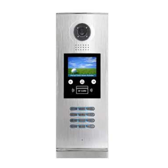
Page 1: Door Station
DMR18S Door Station User Manual RF CARD Please read this manual carefully before using the product you purchase, and keep it well for future use.We reserve the right to modify the specification in this manual at any time without notice. -
Page 2: Parts And Functions
1.Parts and Functions Camera Lens Night View LED Adjustable Camera Speaker LCD Screen Touch Key Connectiong Port ID Card Window RF CARD Digital Keypad Microphone 128 mm With rainy cover 2. Terminal Descriptions SD Card Slot T/R - T/R+ CN-LK J/KMB JP-LK •... -
Page 3: Door Station Mounting
3.Door Station Mounting Surface mounting Camera angle The view for rainy Adjust the camera angle and attach the Drill holes in the wall to match the size of cover after mounted metal to the panel and wire correctly. screws and attach the rainy cover to the wall. Attach screws to fix the Attach the unit to the rainy The last view for all mounting... -
Page 4: Flush Mounting
Flush mounting Camera angle Drill a hole and attach the The view for rainy Adjust the camera angle and attach the rainy cover to it cover after mounted metal to the panel and wire correctly. Attach screws to fix the Attach the unit to the rainy Attach the baffle to protect metal box... - Page 5 4. System Connection Impedance Code=31 Code=30 OFF ON switch Code=29 Code=28 Code=3 Code=2 Impedance OFF ON switch Code=1 Code=0 100~240VAC BUS(IM) BUS(DS) RF CARD ID Code=0 NOTE:Here we take DT47M(the monitor) for example.
-
Page 6: Door Lock Connections
5. Door Lock Connections 1. Internal Power Supply Mode Use the power of the system to supply for the electronic lock, so that the lock can be connected to the door station directly, without an additional power supply for the electronic lock. Note that the door station can only output 12Vdc power, therefore the kind of lock is limited. • The rated power of the lock must be less than 12Vdc 300mA when using internal power supply mode • The GND must connect to the negative of the lock, and the COM connect to the positive . • Jumper set to 1-2 position for Power-off-to-Unlock safety type(Normally closed mode); set to 2-3 position for Power-on-to -Unlock type(Normally open mode ). • If different unlocking time is needed to be configured, change the Unlock Timing on door station.(In debug state, press [1 #] --> [1] Installer Setup--> [2]Unlock Timing) A. - Page 7 2. External Power Supply Mode When the electronic lock is over 12 Vdc, additional power supply for the lock is needed. • The power supply for the lock must be less than 48Vdc 1.5A. • The Jumper must be removed when using external power supply. The default setting is Power-on-to-Unlock type(Normally open mode), if use Power-off-to-Unlock type, change the Unlock Relay mode to Normally closed mode . • If different unlocking time is needed to be configured, change the Unlock Timing on door station.(In debug state, press [1 #] --> [1] Installer Setup--> [2]Unlock Timing) C. Connection for Power-to-Unlock type: set to Normally Open on the +12V LK - (GND) Unlock Relay mode (default) LK+(COM) N.O.
-
Page 8: Code
1. About room code(address): Room Code(also called room address) is a code assigned to each monitor, to identify different monitors; each monitor have a unique room code in one buidling.The room Code is stored in each Monitor’s inner EEPROM memory, and does not lose even the monitor is power off. 2. About Debug State: The Debug State is your starting point for using all the applications on DMR18S. > > D e b u g S t a t e < < 0 - # R e d i a l RF CARD 1 - #... -
Page 9: Id Code
Table 1: Item Submenu 1. ID Code [0] 2. Unlock Timing [01] 3. Unlock Output [0] 4. Monitor Timing [600] 5. Doorplate Mode [0] 1. Installer Setup 6. Waiting Timing [040] 7. Talking Timing [090] 8. Installer Code ... 9. Default ... 1. Language [0] 2. Tone Select [01] 3. Tone Volume [3] 4. Unlock Code [1111] 5. Work Mode [0] 2. Setup 6. Clock ... 7. Setup Code ... 8. About ... 9. Default ... 1. Add Card ... 2. Delete By Card 3. Delete By M.code 3. Card Manage 4. Cards Information 5. Format To search the online monitors,input the monitor code 4. Online Monitors number to search To search the online door stations.Max.4 door station 5. -
Page 10: Code
Basic Tools Detail: Table 2(Installer Setup): Factory Item Description If only one door station is installed in this building, set to 0; If multi door stations are installed, primary door station ID Code Single must be set to 0, and other slave door stations must be set from 1 to 3. Note that max. 4 door stations are available in one building To set the time that how long the door keeps open [01] Unlock Timing when door is released. Range from 01 to 99 seconds. 1 seconds To set the unlock mode to match the corresponding lock.Range from 0 to 1. Unlock Output 0:Power-on-to-Unlock Mode(Normally Open Mode) 1:Power-off-to-Unlock Mode(Normally Closed Mode) Monitor Timing To show the monitor time,Range from 6s to 600s 600s To set the calling mode.If set to 0,it's the auto mode,that means the calling will be activated directly Doorplate Mode after inputting 2 digits code.If set to 1,it's the manual Auto mode mode,that means you should press "#" button to activate the calling after inputting the code. Waiting Timing To show the calling wait time,Range from 6s to 600s To show the limitation time of talking,Range from 6s to Talking Timing 600s Installer Code ... -
Page 11: Code
Table 3(Setup): Factory Item Description Language reserved. Tone Select Select the chime of Door Station in calling wait state. Adjust the tone volume for dooor station in calling.Range Tone Volume from 01~15 To change unlock code in Common Code Unlock mode, in Unlock Code 1111 4-digits format. 1111 is the default unlock code. 0: Standard work mode; 1: DJ work mode; Work Mode 2: Router work mode; 3. Gateway work mode. To set date and time. Date format:if set to 0,date format is DD/MM/YY,if set to Clock ... 1,date format is MM/DD/YY. Time format: if set to 0,time format is 24 hour standard.If set to 1,time format is12 hour standard. -
Page 12: Code
Table 4(Card Manage): Factory Item Description Add Card ... To add the user card Delete By Card To delete card by user card Delete By M.code To delete card by room code Cards Information To show the informations about cards Format To format informations about cards 4. How to use code unlock function: Please refer to the following operations: [8017 ] [ - - - - ] Door Open RF CARD RF CARD Please Input Password When the Door Station is in Input 4 digits Unlock Code If verified correctly, standby, Press “#”... - Page 13 9 . D e f a u l t *Back *Back # Save Please Input Password Press “#”,Input “8002”, Press “4” to enter unlock Input 4 digits number, then input Setup Code or code item. then press “#” to update Admin Code(88888888 or 66666666 by default) 6. User Card Management: This section explains how to configure the key fob function on DMR18S, The key fob is used to open the lock. Total 320 key fobs can be registered with one door station. When swiping the fob to the door station, the distance must be less than 3 centimeter. Key Fobs must be registered on the Door station that can be used to open the door. Register the Key Fobs: All the registered key fobs are called User Cards/User Key Fobs. New fobs/cards need to be registered one by one to the Door station to become a valid User Card/User Key Fob; and every User Card/User Key Fob is related to a certain Monitor Address (Flat code). When the Doors tation is standby, press [#] --> [9008] -->Password([66666666 by default]) to get into the Debug Mode Menu, then Press [1 #] --> [3] Card Manage -->[1] Add Card to get into the Add Card page. Please see the followings.
- Page 14 1 . A d d C a r d . . . 1 . A d d C a r d . . . 1 . A d d C a r d . . . [ - - - ] [ 0 0 1 ] [ 0 0 1 ] Updated...
-
Page 15: Power Supply
Card information: 4 . C a r d s I n f o r m a t i o n Enter Card Information page, and the screen will display the authorized User Cards count, and card read access Card Count: 320 events count. * Back # Save Format: 5 . F o r m a t Enter Card Format page, a password [ - - - - - - - - ] will be asked,input 8 digits installer... - Page 16 DT-ENG-DMR18S-V1 2015S0520...
Need help?
Do you have a question about the DMR18S and is the answer not in the manual?
Questions and answers