
Related Manuals for V-Tec DT596/KP


Summary of Contents for V-Tec DT596/KP
- Page 1 2 -Wire Intercom System DT596(F)KP User Manual DT596/KP DT596F/KP DT-ENG-596(F)KP-V2 110S714...
-
Page 2: Table Of Contents
Contents 1.Parts and Functions..................... 1 2.Terminal Descriptions ..................1 3.Door Station Mounting ..................2 4.System Wiring and Connections ................. 4 5.DIP Switches Setting ................... 11 6. Functions Setting Up ..................12 7.Unlock Operations ....................18 8.Power Supply Instructions ................... 19 9. -
Page 3: Parts And Functions
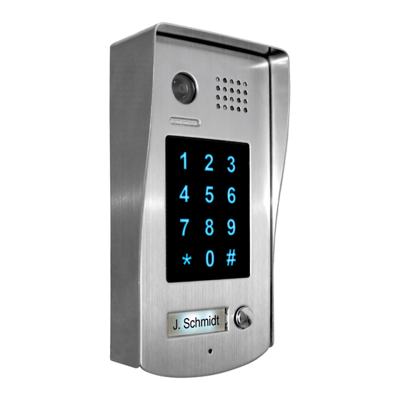
1.Parts and Functions Camera Lens Speaker Indicator(red) Indicator(blue) Touch Sensitive Digital Keypad 28 mm Nameplate Call Button Microphone Rainy Cover DT596/KP 90 mm Camera Lens Speaker Indicator(red) Indicator(blue) Touch Sensitive Digital Keypad Nameplate Call Button Screws for panel mounting Microphone... -
Page 4: Door Station Mounting
• • S1+,•S2+:•Lock•power(+)•output,•to•connect•2•locks. • • S-:•Lock•power(-)•output,•connect•to•the•power(-)•input•of•locks(only•when•using•the•camera•to• power•the•locks,•if•using•the•external•power•supply•for•the•locks,•the•S-•will•not•be•connected). 3.Door Station Mounting DT596/KP Mounting adjust camera angle Drill holes in the wall to match the size of Connect the cable correctly and adjust screws and attach the rainy cover to the wall. -
Page 5: Adjusting Camera Angle
DT596F/KP Mounting adjust camera angle Drill a hole in the wall to match the size of the Connect the cable correctly and adjust mounting box and attach to the wall. right angle for camera Attach the panel to the mounting box and Place name label use screws supplied to fix the panel Adjusting Camera Angle... -
Page 6: System Wiring And Connections
Placing Name Label Move•the•plastic•cover•away•to•open•the•transparent•name•label•cover,••insert•a•name•paper,•then•put• the•plastic•cover•back•to•the•panel.• 4.System Wiring and Connections Basic Connection monitor L1 L2 PL S1+ S2+ S-... -
Page 7: Electric Lock Connection
Electric Lock Connection Door Lock Controlled with Internal Power •••••Note: 1.• Electronic•lock•of•Power-on-to-unlock•type•should•be•used. 2.• The•door•lock•is•limited•to•12V,•and•holding•current•must•be•less•than•250mA. 3.• The•door•lock•control•is•not•timed•from•Exit•Button(EB). 4.• The•Unlock Mode•Parameter•of•Monitor•must•be•set•to•0•(by•default). 1 2 3 1 2 3 Connect one lock Connect two locks Jumper position in Jumper position in LOCK LOCK LOCK Door Lock Controlled with Dry Contact •••••Note: 1.•... - Page 8 connect•one•lock connect•two•locks Take off the Jumper Take off the Jumper POWER POWER SUPPLY SUPPLY LOCK LOCK LOCK Unlock parameter setting(set in monitor) H/W : a1.3 S/W: V17.11.418.00 Manual Monitor Intercom Multimedia Local addr: Monitor Unlock timing: Video standard: UI-CODE: User Setup Close Memory Album...
-
Page 9: Multi Door Stations Connection
Multi Door Stations Connection monitors DBC4 A B C D 85~260VAC 4# Camera 3# Camera 2# Camera 1# Camera ID=11 ID=01 ID=00 ID=10 1 2 3 4 1 2 3 4 1 2 3 4 1 2 3 4 L1 L2 PL S1+ S2+ S- L1 L2 PL S1+ S2+ S- L1 L2 PL S1+ S2+ S- L1 L2 PL S1+ S2+ S-... -
Page 10: Multi Monitors Connection
Multi Monitors Connection Basic IN-OUT Wiring Mode monitor 3 4 5 6 Code=15, DIP-6=on monitor 3 4 5 6 Code=14, DIP-6=off monitor 3 4 5 6 Code=0, DIP-6=off 85~260AC ID=00 1 2 3 4... - Page 11 With DBC-4 Wiring Mode monitor monitor 3 4 5 6 3 4 5 6 Code=14, DIP-6=on Code=15, DIP-6=on monitor monitor 3 4 5 6 3 4 5 6 Code=12, DIP-6=on Code=13, DIP-6=on monitor monitor 3 4 5 6 3 4 5 6 Code=2, DIP-6=on Code=3, DIP-6=on monitor...
- Page 12 Extending Connections with DCU unit CALL CALL UNLOCK UNLOCK TALK/MON TALK/MON IN-USE IN-USE 3 4 5 6 3 4 5 6 Code=3, DIP-6=on Code=2, DIP-6=on CALL CALL UNLOCK UNLOCK TALK/MON TALK/MON IN-USE IN-USE 3 4 5 6 3 4 5 6 Code=1, DIP-6=on Code=0, DIP-6=on DCU Code =3(11)
-
Page 13: Dip Switches Setting
5.DIP Switches Setting ON(1) OFF(0) DIP Switches Settings of Door Station Total•4•bits•on•the•DIP•switches•can•be•configured.The•switches•can•be•modified•either•before•or•after•installation. Setting Item Bit state Descriptions Default•setting,•ID•=•0(00),•set•to•the•first•Door•Station. 1 2 34 ID•=•1(10),•set•to•the•second•Door•Station. Bit1•and•Bit2 1 2 34 (it•is•used•to•set•the•ID• ID•=•2(01),•set•to•the•third•Door•Station. code•for•door•station) 1 2 34 ID•=•3(11),•set•to•the•fourth•Door•Station. 1 2 34 Activate• alarm• function,• S2+• and• S-• terminals• are• used• to• connect•alarm.Please•note•that•the•second•lock•can•not•be•... -
Page 14: Functions Setting Up
Bit-1•to•Bit-5•are•used•to•User•Code•setting.The•DT596•responds•to•0~15•. Bit state User Code Bit state User Code Bit state User Code Code=0 Code=6 Code=11 3 4 5 3 4 5 3 4 5 Code=1 Code=7 Code=12 3 4 5 3 4 5 3 4 5 Code=2 Code=8 Code=13 3 4 5 3 4 5 3 4 5... - Page 15 Order Setting items Setting range Default value Setting code Reset•all•settings 1234 1•~•12•digits Setting•the•master•code 1234 Valid•keys:0•~•9 Setting•the•key 10•to•99•seconds/ 10•seconds illumination•time continually•lit Setting•the•unlock•time 01•to•99•seconds 1•seconds Setting•the•unlock•mode •0:opened/1:closed opened Operation•tone•settings 0:on/1:off Reset•code•settings 1234 &#•function•settings 0:Normal/1:Reverse Normal Call•tone•settings 0:Enable/1:Disable Enable Interference•resistant•• Valid•keys:0•~•5 grade•settings Reserve Reserve Reserve 10~17...
- Page 16 blue Each•operation•is•indicated•by•the•lighting•up•of•the•LED• indicators• on• the• right• section• of• the• unit,• and• by• the• sounding•of•the•buzzer. (red) (blue) Input the master code. (Default: [ ] +[#] ) Beep+, Beep 1.Reset all settings 2.Setting the master code 3.Setting the key 4.Setting the illumination time unlock time (Default 1234) (Default 10s)
- Page 17 (red) (blue) Input the master code. (Default: [ ] +[#]) Beep+, Beep 5.Setting the unlock mode 6.Setting operation tone 7.Reset code setting 8. &# function setting (Default 0(opened)) (Default ON) (Default Normal) Input the setting code. Input the setting code. Input the setting code.
- Page 18 (red) (blue) Input the master code. (Default: [ ] +[#]) Beep+, Beep 9. Call tone setting 10.Interference resistant grade setting (Default enable) (Default 2) Input the setting code. Input the setting code. 08+# 09+# (red) (blue) (red) (blue) Beep+, Beep Beep+, Beep Inputting of code (ex.: 1) Inputting of code (ex.: 3)
- Page 19 (red) (blue) Input the master code. (Default: [ ]+[#] ) Beep+, Beep 12.Setting the code 13.Setting the code 14.Setting the code 15.Setting the code forTemporary1 forTemporary2 for user group1 for user group2 20~59 60~99 Input the setting code. Input the setting code. Input the setting code.
-
Page 20: Unlock Operations
7.Unlock Operations Unlocking of user code When•the•registered•user•code•has•been•input•using•the•keypad•(1~12•digits),•the•LED•indicator•(group 1:•red,•group•2:•blue)•lights•up,•the•buzzer•sounds,and•the•electric•door•strike•is•unlocked.(note•that• you•should•press•"#"•button(if•"#"•button•is•set•to•confirm•button)•after•input•the•unlock•code) Example:group•1 Example:group•2 ••••••••••••••2011 ••••••••••••••2012 Red LED lights up Blue LED lights up (during relay1 operation) (during relay2 operation) (red) (blue) (red) (blue) Beep+ Beep+ • • The•time•interval•during•which•the•button•must•be•pressed•is•approximately•10•seconds.•If•the• time•interval•exceeds•approximately•10•seconds,•the•input•value•will•be•cleared. • • If•you•make•a•mistake•when•inputting•the•user•code,press•the"•cancel"•button•and•input•the•user• code•again. -
Page 21: Power Supply Instructions
• • Unlocking•time:•• • • • 1~99s • • Lock•Power•supply:•• • • 12Vdc,•300mA(Internal•Power); • • Number•of•relay•circuits:•• • • • • Mounting:• • • •••••••••••••••••Surface•mounting(DT596/KP)•••••••••••••••••••••••••••••••••• ••••••••••••••••••••••••••••••••••••••••••••••••••••••••••••Flush•mounting•(DT596F/KP)••••••••••••••• • • Working•temperature:• • • •-10ºC•~•+45ºC • • Dimension:• • • • 176(H)×90(W)×28(D)mm(DT596/KP) ••••••••••••••••••••••••••••••••••••••••••••••••••••••••••••••••••••••••••••220(H)×119(W)×52(D)mm(DT596F/KP) -19-... -
Page 22: Cables Requirements
11.Cables Requirements The•maximum•distance•of•the•wiring•is•limited•in•the•DT•system.•Using•different•cables•may•also•affect•the• maximum•distance•which•the•system•can•reach.• The farest monitor monitor with two or four monitors monitor monitor DBC/DBC-4 When Monitor quantity < 20 Cable Usage 60• 60• 30• Twisted•cable•2x0.75•mm 80• 80• 40• Twisted•cable•2x1•mm When Monitor quantity > 20 Cable Usage 70• 30• 20•... - Page 23 Note:...
- Page 24 The design and specifications can be modified without notice to the user. Right to interpret and copyright of this manual are reserved. DT-ENG-596(F)KP-V2 110S714...
- Page 25 • Stromversorgung : 24 V über PS4 o. PS5 mit DPS • Stromverbrauch : 2 W Standby und 5 W im Betrieb • Monitorgröße : 3,5 " /8,89 cm • Display Auflösung: 320x240 mm • Abmessungen : 220x105x20 mm Kabelempfehlungen...
- Page 26 Twisted-Pair-Kabel nicht geschirmt, oder Kabel mit verdrillten Adernpaaren Info Wiki Länge v. Länge von DPS Zu verwendendes Länge vom DBC Türstation zum zum letzen Kabel auf einer Etage Verteiler DPS Monitor >20 Monitore >20 Monitore UTP verdrehtes >20 Monitore 20//< 70m//<...
- Page 27 Master und Slave Einstellungen gilt nur für das DMR11 System nicht für DT592-591 . I Guard unit Call ( Wachmann Monitor/Pförtner ) Sie können einen Monitor im DT System als Guard unit z.B. Pförtner Hausverwalter oder Wachdienst festlegen Untermenü Advance Setup: Zum einschalten betätigen und Code 2008 # eingeben Menü...
- Page 28 Operation Memo (nur wenn Sie mit Memofunktion bestellt haben ) Hinweis: Die Bilder können sowohl manuell als auch automatisch gespeichert werden. Maximale Kapazität 120 Stück das älteste wird ersetzt , wenn der Speicher voll ist. Manuelle Aufnahme : Wenn der Bildschirm an ist und Sie ein Bild des Gastes aufnehmen wollen drücken Sie REC zur Aufnahme des aktuellen Bildes.
Need help?
Do you have a question about the DT596/KP and is the answer not in the manual?
Questions and answers