Advertisement
INTRODUCTION...........................................................................2
Installation Guide........................................................................2
CONFIGURATIONS......................................................................4
Debug State...............................................................................4
Work Mode.................................................................................8
Software Update........................................................................10
Tone Update..............................................................................10
UI Update...................................................................................11
Namelist Update.........................................................................12
by SD Card..............................................................................12
by DT-Config............................................................................13
DMR18S TECHNICAL MANUAL
2-wire Intercom System
CONTENTS
RF CARD
1
2
3
4
5
6
7
8
9
0
#
*
Advertisement
Table of Contents

Related Manuals for V-Tec 2Easy DMR18s


Summary of Contents for V-Tec 2Easy DMR18s
-
Page 1: Table Of Contents
DMR18S TECHNICAL MANUAL 2-wire Intercom System CONTENTS INTRODUCTION................2 Installation Guide................2 CONFIGURATIONS..............4 Debug State................4 Work Mode.................8 Software Update................10 Tone Update................10 RF CARD UI Update...................11 Namelist Update.................12 by SD Card................12 by DT-Config................13... -
Page 2: Introduction
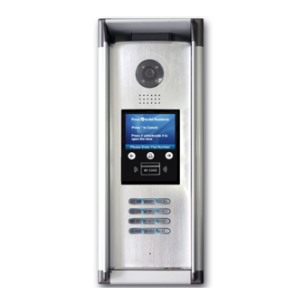
INTRODUCTIONS Installation Guide DESCRIPTION MOUNTING As an upgrade of DMR18, DMR18s has more stable and stronger abil- Surface mounting ity of communication. It achieves call model of 128 families, expands capacity of the system. It also adds many special functions such as select by touching keypad, namelist, voice prompt, etc. - Page 3 INTRODUCTIONS Installation Guide SYSTEM CONNECTION ELECTRIC LOCK CONNECTION 1) Door Lock Controlled with Internal Power 1. The door lock is limited to 12Vdc, and holding current must be less than 250mA when using internal power supply mode. Code=31 Code=30 Impedance OFF ON switch 2.
-
Page 4: Configurations
CONFIGURATIONS Debug State Descriptions: DEBUG STATE 1.ID Code: Select item 1 to enter ID Code setting page. You can input The Debug State is your starting point for using all the applications on 0~3 to set as door 1 ~ door 4. DMR18S. - Page 5 CONFIGURATIONS Debug State 9.Default: Select item 9 to enter Default setting page. Input the setup code to restore factory setting. 5. Doorplate Mode 5. Doorplate Mode [11] [ - ] [ : : : : : : : : ] Input 0 0: * 1: 123...
- Page 6 CONFIGURATIONS Debug State 4.Unlock Code: Select item 4 to enter Unlock Code setting page. 8.About: Select item 8 to enter About page. The information includes 1111 is the default unlock code. Input 4 digit numbers to set a new Hardware version, Software Version etc. code(Except for 8001~8019 and 9008).
- Page 7 CONFIGURATIONS Debug State 2.Delete Card: ONLINE MONITORS • Select item 2 to Delete By Card. To search the Gateway and Online Monitors,input the monitor code number to search. 2. Delete By Card 2. Delete By Card > > D e b u g S t a t e < < Updated 4.
-
Page 8: Work Mode
CONFIGURATIONS Work Mode DT-DJ MODE DEFINITION Total four different work modes are available for DMR18S to accom- Work Mode set to 1: modate different situation. In standby mode, input #8002 + code (66666666) and select “ 5 ” item to enter Work Mode setting page. The DT-DJ Mode is used for the audio intercom system. - Page 9 CONFIGURATIONS Work Mode DT-BDU ROUTER MODE DT-BDU GATEWAY MODE The Router Mode is used for the big capacity system which has plen- The Gateway Mode is used for the community network system, the ty of apartments for blocks with BDU unit. The namelist can be updat- common door station is connected in the system which can call all the ed by SD Card or DT-Config (More details refer to Update Namelist monitors.
-
Page 10: Software Update
CONFIGURATIONS System Update 5. Insert the SD card to slot, the information of “Download...” will be DESCRIPTIONS showed when the updated is in progress. After 3 seconds, a long sound “BP+” will be heard to start the updated. This section is used for the software version V000101 of DMR18S. (After 2015.07.10);... -
Page 11: Ui Update
CONFIGURATIONS System Update • If other languages are needed for you, please record the audio file 7. Check the Tone which language you want. 1. Language 2. Tone Select [01] 2. Tone Select [01] 3. Tone Volume Setup Mute • Then provide the audio file to our company, a Ring.bin file will be 4. -
Page 12: Namelist Update
CONFIGURATIONS System Update 3. Copy the Update UI file to SD card by computer. 6. When update is finished, it will return to Standby Mode interface. And show the new UI. 4. Select 3 to enter UI update,the information of “update ready” will NAMELIST UPDATE be showed. -
Page 13: By Dt-Config
CONFIGURATIONS System Update 3. Copy the Namelist file to SD card by computer. 2) Namelist update by DT-Config DMR18S-Config software is for parameters setting, namelist setting etc. It is great convenience to installation. The DMR18S-Config software operation is as follows: 1. - Page 14 CONFIGURATIONS System Update • Check Name List on DMR18S Set the DMR18S Work Mode as 0 (more details refer to Work Mode setting section). • Press touch button to enter Name List page. See the following picture shows. 4. Edit Namelist 4.1 Apartments •...
- Page 15 CONFIGURATIONS System Update • • Check Name List on DMR18S Check Name List on DMR18S Set the DMR18S Work Mode as3 (more details refer to Work Mode Set the DMR18S Work Mode as 2 (more details refer to Work Mode setting section).
Need help?
Do you have a question about the 2Easy DMR18s and is the answer not in the manual?
Questions and answers