Table of Contents
Advertisement
Advertisement
Chapters
Table of Contents

Related Manuals for IEI Technology IMB-9454G-R20


Summary of Contents for IEI Technology IMB-9454G-R20
- Page 1 IMB-9454G Motherboard IMB-9454G-R20...
- Page 2 REVISION HISTORY Title IMB-9454G-R20 Intel Pentium D/Celeron D Motherboard Revision Number Description Date of Issue Added Intel® Core™ 2 Duo December 2006 to the supported CPU list Initial release September 2006 COPYRIGHT NOTICE The information in this document is subject to change without prior notice in order to improve reliability, design and function and does not represent a commitment on the part of the manufacturer.
-
Page 3: Table Of Contents
IMB-9454G Motherboard Table of Contents INTRODUCTION....................15 1.1 IMB-9454G O ................... 16 VERVIEW 1.1.1 IMB-9454G Applications ................. 16 1.1.2 IMB-9454G Benefits ..................16 1.1.3 IMB-9454G Features ..................17 1.2 IMB-9454G B ................17 OARD VERVIEW 1.2.1 IMB-9454G Connectors................... 18 1.2.2 Technical Specifications................... 19 DETAILED SPECIFICATIONS ................ - Page 4 2.11 R ....................29 LOCK 2.12 I DA) I ..........29 NFRARED SSOCIATION NTERFACE 2.13 USB I ....................29 NTERFACES 2.14 BIOS ........................29 2.15 O ........29 PERATING EMPERATURE AND EMPERATURE ONTROL 2.16 A ......................30 UDIO ODEC 2.17 P ...................
- Page 5 IMB-9454G Motherboard 3.2.19 SPDIF Connector................... 60 3.2.20 TPM Connector....................62 3.2.21 Internal USB Connectors................63 3.3 E ............... 64 XTERNAL NTERFACE ONNECTORS 3.3.1 Audio Connectors..................... 65 3.3.2 CRT Connector ....................65 3.3.3 Ethernet Connectors ..................66 3.3.4 Keyboard/Mouse Connector ................67 3.3.5 Serial Port Connectors ..................
- Page 6 4.8.1 LCD Panel Connection ..................90 4.8.2 Ethernet Connection ..................90 4.8.3 USB Connection....................90 4.8.4 Serial Connection..................... 90 4.8.5 Keyboard and Mouse Connection..............90 4.8.6 Audio Interface....................90 AMI BIOS SETUP....................91 5.1 I ......................92 NTRODUCTION 5.1.1 Starting Setup....................92 5.1.2 Using Setup ......................
- Page 7 IMB-9454G Motherboard 5.6.1 North Bridge Configuration................131 5.7 E ........................133 SOFTWARE DRIVERS ..................135 6.1 A ................136 VAILABLE OFTWARE RIVERS 6.2 C ................136 HIPSET RIVER NSTALLATION 6.3 VGA D ......................139 RIVER 6.4 B LAN D E LAN) I ........
- Page 8 List of Figures Figure 1-1: IMB-9454G Board Overview (Top View) ..........17 Figure 2-1: IMB-9454G Dimensions (mm) ..............22 Figure 2-2: External Interface Panel Dimensions (mm)...........23 Figure 3-1: Connector and Jumper Locations ............34 Figure 3-2: Audio Connector Location..............38 Figure 3-3: Audio CD-in Connector Location............39 Figure 3-4: Audio AUX-in Connector Location ............40 Figure 3-5: CPU 12V Power Connector Location.............41 Figure 3-6: Fan Connector Locations ...............42...
- Page 9 IMB-9454G Motherboard Figure 3-27: PS/2 Pinouts...................68 Figure 3-28: External Serial Port Connector ............69 Figure 3-29 Parallel Port Connector Pinout Locations..........70 Figure 4-1: Intel LGA775 Socket ................78 Figure 4-2: Remove the CPU Socket Protective Shield...........79 Figure 4-3: Open the CPU Socket Load Plate ............79 Figure 4-4: Insert the Socket LGA775 CPU ..............80 Figure 4-5: IEI LGA-775 Cooling Kit ................81 Figure 4-6: Securing the Heat sink to the PCB Board ..........82...
- Page 10 Figure 6-20: Audio Driver Install Shield Wizard Starting ........148 Figure 6-21: Audio Driver Setup Preparation ............148 Figure 6-22: Audio Driver Digital Signal ..............149 Figure 6-23: Audio Driver Installation Continues ..........149 Figure 6-24: Audio Driver Installation Complete........... 150 Figure 6-25: Preparing Setup Screen ..............
- Page 11 IMB-9454G Motherboard List of Tables Table 1-1: Technical Specifications ................20 Table-2-1: Supported CPUs..................23 Table 2-2: Power Consumption .................31 Table 3-1: Peripheral Interface Connectors..............36 Table 3-2: Rear Panel Connectors................37 Table 3-3: On-board Jumpers ..................37 Table 3-4: Audio Connector Pinouts .................38 Table 3-5: Audio CD-in Connector Pinouts ..............39 Table 3-6: Audio AUX-in Connector Pinouts............40 Table 3-7: CPU 12V Power Connector Pinouts ............41 Table 3-8: CPU Fan Connector Pinouts ..............42...
- Page 12 Table 3-27: VGA Connector Pinouts .................66 Table 3-28: LAN1 and LAN2 Pinouts .................67 Table 3-29: RJ-45 Ethernet Connector LEDs............67 Table 3-30: PS/2 Connector Pinouts .................68 Table 3-31: External Serial Port Pinouts ..............69 Table 3-32: Parallel Port Connector Pinouts ............70 Table 3-33: External USB Connector Pinouts ............71 Table 4-1: IEI Provided Cables...................85 Table 4-2: On-board Jumpers ..................87 Table 4-3: Clear CMOS Jumper Settings ..............89...
- Page 13 IMB-9454G Motherboard List of BIOS Menus BIOS Menu 1: Main ....................94 BIOS Menu 2: Advanced.....................96 BIOS Menu 3: CPU Configuration................97 BIOS Menu 4: IDE Configuration ................98 BIOS Menu 5: IDE Master and IDE Slave Configuration........100 BIOS Menu 6: Floppy Configuration ..............104 BIOS Menu 7: Super IO Configuration ..............
- Page 14 Glossary AC ’97 Audio Codec 97 Hard Disk Drive ACPI Advanced Configuration and Integrated Data Electronics Power Interface Input/Output Advanced Power Management ICH4 I/O Controller Hub 4 ARMD ATAPI Removable Media Device L1 Cache Level 1 Cache ASKIR Shift Keyed Infrared L2 Cache Level 2 Cache Advanced Technology Liquid Crystal Display...
-
Page 15: Introduction
IMB-9454G Motherboard Chapter Introduction Page 15... -
Page 16: Imb-9454G Overview
IMB-9454G Motherboard 1.1 IMB-9454G Overview The Micro ATX form factor IMB-9454G with Pentium 4 / Pentium D / Celeron D CPU platform is fully equipped with latest technology and advanced multi-mode I/Os. The IMB-9454G is designed for system manufacturers, integrators, and VARs that want performance, reliability, and quality at a reasonable price. -
Page 17: Imb-9454G Features
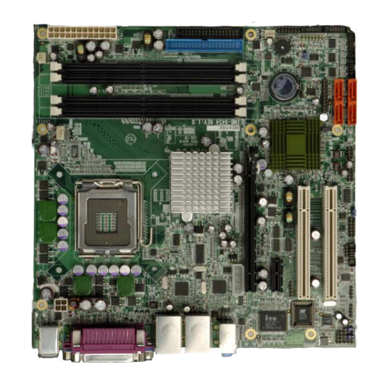
IMB-9454G Motherboard 1.1.3 IMB-9454G Features Some of the IMB-9454G features are listed below: Complies with RoHS Supports Intel® Pentium 4 / Pentium D / Celeron D CPUs Supports a maximum front side bus (FSB) speed up to 1066MHz Supports up to 4GB of 400MHz, 533MHz or 667MHz of DDRII memory Comes with two high performance gigabit Ethernet (GbE) controller Supports four SATA channels with transfer rates up to 300MB/s Supports eight USB 2.0 devices... -
Page 18: Imb-9454G Connectors
IMB-9454G Motherboard 1.2.1 IMB-9454G Connectors The IMB-9454G has the following connectors on-board: 1 x Audio connector 1 x Audio CD-in connector 1 x Audio AUX-in connector 1 x CPU 12V power connector 2 x DDRII DIMM sockets 3 x Fan connectors 1 x FDD connector 1 x Front panel audio connector 1 x Front panel connector... -
Page 19: Technical Specifications
IMB-9454G Motherboard The IMB-9454G has the following on-board jumpers: Clear CMOS COM2 mode selection (RS-232/422/485) The location of these connectors on the motherboard can be seen in Figure 1-1. These connectors are fully described in Chapter 3. 1.2.2 Technical Specifications IMB-9454G technical specifications are listed in Table 1-1. -
Page 20: Table 1-1: Technical Specifications
IMB-9454G Motherboard Two PCI slots Super I/O ITE8712 IrDA By super I/O Digital I/O 4 input / 4 output by super I/O Audio Interfaces One Audio Codec ’97 (AC’97) version 2.3 connector Ethernet Dual Broadcom BCM5787 for PCI Express GbE BIOS AMI flash BIOS Power... -
Page 21: Detailed Specifications
IMB-9454G Motherboard Chapter Detailed Specifications Page 21... -
Page 22: Overview
IMB-9454G Motherboard 2.1 Overview This chapter describes the specifications and on-board features of the IMB-9454G in detail. 2.2 Dimensions 2.2.1 Board Dimensions The dimensions of the board are listed below: Length: 243.84mm Width: 243.84mm Figure 2-1: IMB-9454G Dimensions (mm) Page 22 IEI ®... -
Page 23: External Interface Panel Dimensions
IMB-9454G Motherboard 2.2.2 External Interface Panel Dimensions External interface panel dimensions are shown in Figure 2-2. Figure 2-2: External Interface Panel Dimensions (mm) 2.3 CPU Support Table-2-1 lists the CPUs supported by the IMB-9454G board. Model Clock Speed L2 Cache Max. -
Page 24: Intel ® Pentium ® D
IMB-9454G Motherboard Architecture Data Prefetch Logic 667-MHz, Source-Synchronous FSB for Standard Voltage processors Advanced Power Management features including Enhanced Intel SpeedStep® Technology Intel Enhanced Deeper Sleep state and Dynamic Cache Sizing ® ® 2.3.2 Intel Pentium ® ® The Intel Pentium D processor comes with the following features: The two full processing cores make it easy to handle multiple applications,... -
Page 25: On-Board Chipsets
IMB-9454G Motherboard giving the processor platform access to larger amounts of memory. 512KB Level 2 Cache enables improved overall system performance by giving the core faster access to larger amounts of the data used most often. Streaming SIMD Extensions Accelerates performance on a wide variety of applications including multimedia, video and audio. -
Page 26: Intel Ich7 Southbridge Chipset
IMB-9454G Motherboard Dual-channel DDR2 memory support 2.4.3 Intel ICH7 Southbridge Chipset The Intel ICH7 southbridge chipset comes with the following features: PCI Express Four PCI Express root ports Supports PCI Express 1.0a Support for full 2.5 Gb/s bandwidth in each direction per x1 lane Integrated serial ATA host controller with data transfer rates up to 300 MB/s Integrated IDE controller Independent timing of up to two dirves... -
Page 27: Memory Support
IMB-9454G Motherboard Combine several video output options (DVI, dual independent display, component, composite, HDTV and LVDS) in a single-card solution MECs enable video input capability and PVR functionality Support a wide range of display types and configurations 2.6 Memory Support The IMB-9454G has four DDRII DIMM sockets and supports four 400MHz, 533MHz or 667MHz DDRII DIMM with a maximum RAM of up to 4GB. -
Page 28: Drive Interfaces
IMB-9454G Motherboard 2.9 Drive Interfaces The IMB-9454G can support the following drive interfaces. 4 x SATA drives 2 x IDE devices 1 x FDD 2.9.1 SATA Drives The IMB-9454G supports four SATAII drives with transfer rates of up to 300MB/s. 2.9.2 IDE Interfaces The IMB-9454G southbridge chipset IDE controller supports up to two IDE devices with the following specifications:... -
Page 29: Real Time Clock
IMB-9454G Motherboard 2.11 Real Time Clock 256-byte battery backed CMOS SRAM 2.12 Infrared Data Association (IrDA) Interface The IMB-9454G IrDA supports the following interfaces. Serial Infrared (SIR) Shift Keyed Infrared (ASKIR) If an IrDA port is need, COM2 must be configured as either SIR or ASKIR mode in the BIOS under Super IO devices. -
Page 30: Audio Codec
IMB-9454G Motherboard are also mounted on the northbridge and southbridge chipsets to ensure the operating temperature of these chips remain low. 2.16 Audio Codec The IMB-9454G has an integrated REALTEK ALC655 CODEC. The ALC655 CODEC is a 16-bit, full-duplex AC'97 Rev. 2.3 compatible six-channel audio CODEC designed for PC multimedia systems, including host/soft audio and AMR/CNR-based designs. -
Page 31: Power Consumption
IMB-9454G Motherboard Standard 48-pin LQFP package EAX™ 1.0 & 2.0 compatible Direct Sound 3D™ compatible A3D™ compatible I3DL2 compatible HRTF 3D positional audio 10-band software equalizer Voice cancellation and key shifting in Karaoke mode AVRack® Media Player Configuration Panel for improved user convenience 2.17 Power Consumption Table 2-2 shows the power consumption parameters for the IMB-9454G when a Pentium 4 processor with a clock speed of 3.2GHz is running with four DDRII 533MHz 512MB... -
Page 32: Optional Accessory Items
IMB-9454G Motherboard 1 x RS-422/485 cable 1 x I/O shielding 1 x Mini jumper pack 1 x Utility CD 1 x Quick Installation Guide 2.18.2 Optional Accessory Items The items shown in the list below are optional accessory items are purchased separately. FDD cable USB cable Page 32... -
Page 33: Connectors And Jumpers
IMB-9454G Motherboard Chapter Connectors and Jumpers Page 33... -
Page 34: Peripheral Interface Connectors
IMB-9454G Motherboard 3.1 Peripheral Interface Connectors Section 3.1.1 shows peripheral interface connector locations. Section 3.1.2 lists all the peripheral interface connectors seen in Section 3.1.1. 3.1.1 IMB-9454G Layout Figure 3-1 shows the on-board peripheral connectors, backplane peripheral connectors and on-board jumpers. Figure 3-1: Connector and Jumper Locations Page 34 IEI ®... -
Page 35: Peripheral Interface Connectors
IMB-9454G Motherboard 3.1.2 Peripheral Interface Connectors Table 3-1 shows a list of the peripheral interface connectors on the IMB-9454G. Detailed descriptions of these connectors can be found in Section 3.2. Connector Type Label Audio connector 8-pin header Audio CD-in connector 4-pin header CD_IN1 Audio AUX-in connector... -
Page 36: Rear Panel Connectors
IMB-9454G Motherboard PCI Express x16 socket PCI Express x16 slot PCIE2 PCI Express power connector 4-pin header PCN1 Power connector 24-pin connector PWR1 RS-422/485 connector 4-pin header Serial port connector (1) 10-pin header COM2 Serial port connector (2) 10-pin header COM3 Serial port connector (3) 10-pin header... -
Page 37: On-Board Jumpers
IMB-9454G Motherboard CRT connector 15-pin female connector 3IN1_DSUB1C Ethernet connector (1) RJ-45 connector LAN/USB1A Ethernet connector (2) RJ-45 connector LAN/USB2A Keyboard/Mouse connector 6-pin mini din connector KBMS1 Serial port connector DB-9 male connector 3IN1_DSUB1B Parallel port connector DB-25 female connector 3IN1_DSUB1A USB 2.0 port (1) USB port connector... -
Page 38: Figure 3-2: Audio Connector Location
IMB-9454G Motherboard CN Location: See Figure 3-2 CN Pinouts: See Table 3-4 The IMB-9454G has a built-in AC ’97 AUDIO CODEC connector directly connected to the audio devices. Figure 3-2: Audio Connector Location PIN NO. DESCRIPTION PIN NO. DESCRIPTION SUROUT_L CENOUT GND AUDIO GND AUDIO... -
Page 39: Audio Cd-In Connector
IMB-9454G Motherboard 3.2.2 Audio CD-in Connector CN Label: CD IN1 CN Type: 4-pin headers (1x4) CN Location: See Figure 3-3 CN Pinouts: See Table 3-5 The 4-pin header connects to audio sources such as CD/DVD-ROM optical drives. Figure 3-3: Audio CD-in Connector Location PIN NO. -
Page 40: Audio Aux-In Connector
IMB-9454G Motherboard 3.2.3 Audio AUX-in Connector CN Label: AUX1 CN Type: 4-pin headers (1x4) CN Location: See Figure 3-4 CN Pinouts: See Table 3-6 The AUX-in connector supports additional audio sources. Figure 3-4: Audio AUX-in Connector Location PIN NO. DESCRIPTION PIN NO. -
Page 41: Fan Connectors
IMB-9454G Motherboard CN Location: See Figure 3-5 CN Pinouts: See Table 3-7 The connector supports the 12V power supply. Figure 3-5: CPU 12V Power Connector Location PIN NO. DESCRIPTION PIN NO. DESCRIPTION +12VDC +12VDC Table 3-7: CPU 12V Power Connector Pinouts 3.2.5 Fan Connectors CN Label: FAN1, FAN2 and FAN3... -
Page 42: Figure 3-6: Fan Connector Locations
IMB-9454G Motherboard The cooling fan connectors on the IMB-9454G provide a 12V, 500mA current to a CPU cooling fan and two system cooling fans. All cooling fans have linear fan speed controlled by BIOS. Figure 3-6: Fan Connector Locations PIN NO. DESCRIPTION +12V Linear control... -
Page 43: Fdd Connector
IMB-9454G Motherboard 3.2.6 FDD Connector CN Label: FDC1 CN Type: 34-pin header (2x17) CN Location: See Figure 3-7 CN Pinouts: See Table 3-10 The floppy disk connector (FDC1) is connected to a floppy disk drive. Figure 3-7: FDD Connector Connector Location PIN NO. -
Page 44: Front Panel Audio Connector
IMB-9454G Motherboard GROUND DRIVE SELECT A# GROUND MOTOR ENABLE B# GROUND DIRECTION# GROUND STEP# GROUND WRITE DATA# GROUND WRITE GATE# GROUND TRACK 0# GROUND WRITE PROTECT# GROUND READ DATA# GROUND SIDE 1 SELECT# GROUND DISK CHANGE# Table 3-10: FDD Connector Pinouts 3.2.7 Front Panel Audio Connector CN Label: CN Type:... -
Page 45: Front Panel Connector
IMB-9454G Motherboard Figure 3-8: Front Panel Audio Connector Location PIN NO. DESCRIPTION PIN NO. DESCRIPTION MIC IN GROUND MIC BIAS LINE OUT (R) LINE OUT (R) Return LINE OUT (L) LINE OUT (L) Return Table 3-11: Front Panel Audio Connector Pinouts 3.2.8 Front Panel Connector CN Label: CN Type:... -
Page 46: Figure 3-9: Front Panel Connector Location
IMB-9454G Motherboard Power ATX Power button Reset button Speaker Figure 3-9: Front Panel Connector Location PIN NO. DESCRIPTION PIN NO. DESCRIPTION ACPILED+ SPEAKER+ ACPILED- ATX POWER BUTTON SPEAKER- IDE LED+ RESET SW IDE LED - Table 3-12: Front Panel Connector Pinouts Page 46 IEI ®... -
Page 47: Gpio Connector
IMB-9454G Motherboard 3.2.9 GPIO Connector CN Label: DIO1 CN Type: 12-pin header (2x6) CN Location: See Figure 3-10 CN Pinouts: See Table 3-13 The General Purpose Input Output (GPIO) connector can be connected to external I/O control devices including sensors, lights, alarms and switches. Figure 3-10: GPIO Connector Location PIN NO. -
Page 48: Ide Connector
IMB-9454G Motherboard 3.2.10 IDE Connector CN Label: IDE1 CN Type: 40-pin header (2x20) CN Location: See Figure 3-11 CN Pinouts: See Table 3-14 One primary 40-pin IDE device connector on the IMB-9454G motherboard supports connectivity to ATA 100 IDE devices with data transfer rates up to 100MB/s. Figure 3-11: IDE Device Connector Location PIN NO. -
Page 49: Ir Interface Connector
IMB-9454G Motherboard PIN NO. DESCRIPTION PIN NO. DESCRIPTION DATA 3 DATA 12 DATA 2 DATA 13 DATA 1 DATA 14 DATA 0 DATA 15 IDE DRQ IOW# IOR# IDE CHRDY IDE DACK INTERRUPT SA 1 SA 0 SA 2 HDC CS0# HDC CS1# HDD ACTIVE# Table 3-14: IDE Connector Pinouts... -
Page 50: Pci Express X1 Slot
IMB-9454G Motherboard Figure 3-12: IR Connector Location PIN NO. DESCRIPTION IR-RX IR-TX Table 3-15: IR Connector Pinouts 3.2.12 PCI Express x1 Slot CN Label: PCIE1 CN Type: 36-pin header (2x18) CN Location: See Figure 3-13 CN Pinouts: See Table 3-16 Page 50 IEI ®... -
Page 51: Figure 3-13: Pci Express X1 Slot Locations
IMB-9454G Motherboard PCIe x1 expansion devices can be inserted into the PCIe x1 slots. Figure 3-13: PCI Express x1 Slot Locations PIN NO. DESCRIPTION PIN NO. DESCRIPTION +12v PRSNT#1 +12v +12v RSVD +12v SMCLK JTAG2 SMDAT JTAG3 JTAG4 +3.3v JTAG5 JTAG1 +3.3v 3.3Vaux... -
Page 52: Pci Express X16 Slot
IMB-9454G Motherboard REFCLK+ HSOp(0) REFCLK- HSOn(0) HSIp(0) PRSNT#2 HSIn(0) Table 3-16: PCI Express x1 Slot Pinouts 3.2.13 PCI Express x16 Slot CN Label: PCIE2 CN Type: 164-pin PCIe x16 slot CN Location: See Figure 3-14 CN Pinouts: See Table 3-17 (Side A) Table 3-18 (Side B) PCIe x16 expansion devices can be inserted into the PCIe x16 slot. -
Page 53: Figure 3-14: Pci Express X16 Slot Location
IMB-9454G Motherboard Figure 3-14: PCI Express x16 Slot Location NAME NAME NAME NAME Name HSIn(1) HSIp(6) HSIp(11) PRSNT#1 HSIn(6) HSIn(11) +12v +12v HSIp(2) HSIn(2) HSIp(7) HSIp(12) JTAG2 HSIn(7) HSIn(12) JTAG3 JTAG4 HSIp(3) RSVD JTAG5 HSIn(3) HSIp(13) +3.3v HSIp(8) HSIn(13) +3.3v RSVD HSIn(8) PWRGD... -
Page 54: Table 3-17: Pcie X16 Side A Pinouts
IMB-9454G Motherboard REFCLK+ HSIp(4) HSIp(9) HSIn(14) REFCLK- HSIn(4) HSIn(9) HSIp(0) HSIp(15) HSIn(0) HSIp(5) HSIp(10) HSIn(15) HSIn(5) HSIn(10) RSVD Table 3-17: PCIe x16 Side A Pinouts NAME NAME NAME NAME +12v +12v HSOp(2) RSVD HSOn(2) HSOp(7) HSOp(12) HSOn(7) HSOn(12) SMCLK SMDAT HSOp(3) PRSNT#2 HSOn(3) -
Page 55: Pci Express Power Connector
IMB-9454G Motherboard 3.2.14 PCI Express power connector CN Label: PCN1 CN Type: 4-pin connector CN Location: See Figure 3-15 CN Pinouts: See Table 3-19 This 4-pin power connector supports the power for PCI Express x16 module. Figure 3-15: PCIe x16 Power Connector Location Page 55... -
Page 56: Power Connector
IMB-9454G Motherboard PIN NO. DESCRIPTION +12V Table 3-19: PCIe x16 Power Connector Pinouts 3.2.15 Power Connector CN Label: PWR1 CN Type: 24-pin connector CN Location: See Figure 3-16 CN Pinouts: See Table 3-20 This 24-pin power connector supports the ATX power supply. Figure 3-16: Power Connector Location Page 56 IEI ®... -
Page 57: Rs-422/485 Connector
IMB-9454G Motherboard PIN NO. DESCRIPTION PIN NO. DESCRIPTION 3.3V 3.3V 3.3V -12V Ground Ground PS_ON Ground Ground Ground Ground Ground PWR_OK 5VSB 3.3V Ground Table 3-20: Power Connector Pinouts 3.2.16 RS-422/485 Connector CN Label: CN Type: 4-pin header (1x4) CN Location: See Figure 3-17 CN Pinouts: See Table 3-21... -
Page 58: Serial Port Connectors
IMB-9454G Motherboard Figure 3-17: RS-422/485 Connector Location PIN NO. DESCRIPTION TXD1+ TXD1- RXD1+ RXD1- Table 3-21: RS-422/485 Connector Pinouts 3.2.17 Serial Port Connectors CN Label: COM2, COM3, COM4, COM5 and COM6 CN Type: 10-pin header (2x5) CN Location: See Figure 3-18 CN Pinouts: See Table 3-22 The serial ports connectors connect to RS-232 serial port device. -
Page 59: Sata Drive Connectors
IMB-9454G Motherboard Figure 3-18: Serial Port Connector Locations PIN NO. DESCRIPTION PIN NO. DESCRIPTION Table 3-22: COM2 COM3, COM4, COM5 and COM6 Pinouts 3.2.18 SATA Drive Connectors CN Label: SATA1, SATA2, SATA3 and SATA4 CN Type: 1x7 pin SATA drive connectors CN Location: See Figure 3-19 CN Pinouts:... -
Page 60: Spdif Connector
IMB-9454G Motherboard The four SATA drive connectors are connected to four SATAII drives. SATAII drives transfer data at speeds as high as 300MB/s. Figure 3-19: SATA Drive Connector Locations PIN NO. DESCRIPTION S_TXP S_TXN S_RXN S_RXP Table 3-23: SATA Drive Connector Pinouts 3.2.19 SPDIF Connector CN Label: CN Type:... -
Page 61: Figure 3-20: Spdif Connector Locations
IMB-9454G Motherboard CN Location: See Figure 3-20 CN Pinouts: See Table 3-24 The SPDIF connector connects to the S/PDIF audio module, which bears S/PDIF digital output. S/PDIF (Sony/Philips Digital Interface) is a newest audio transfer file format, which allows the user to enjoy digital audio. Figure 3-20: SPDIF Connector Locations PIN NO. -
Page 62: Tpm Connector
IMB-9454G Motherboard 3.2.20 TPM Connector CN Label: TPM1 CN Type: 20-pin connector CN Location: See Figure 3-21 CN Pinouts: See Table 3-25 The TPM (Trusted Platform Module) connector is a device with a controller that is used to check authenticity of digital signs and keys as well as other encryption and security functions. -
Page 63: Internal Usb Connectors
IMB-9454G Motherboard SMB_CLOCK SMB_DATA +3.3SBY SER_IRQ CLKRUN# LPC_PD# LDRQ# Table 3-25: TPM Connector Pinouts 3.2.21 Internal USB Connectors CN Label: USB3 and USB4 CN Type: 8-pin header (2x4) CN Location: See Figure 3-22 CN Pinouts: See Table 3-26 One 2x4 pin connector provides connectivity to two USB 2.0 ports. The USB ports are used for I/O bus expansion. -
Page 64: External Interface Connectors
IMB-9454G Motherboard PIN NO. DESCRIPTION PIN NO. DESCRIPTION USBD0- USBD0+ USBD0+ USBD0- Table 3-26: USB3 and USB4 Pinouts 3.3 External Interface Connectors The peripheral connectors on the back panel are connected to devices externally when the IMB-9454G is installed in a chassis. The peripheral connectors on the rear panel are: 3 x Audio jacks 1 x CRT connector 2 x RJ-45 Ethernet connectors... -
Page 65: Audio Connectors
IMB-9454G Motherboard 3.3.1 Audio Connectors CN Label: CN Type: Audio jack CN Location: See Figure 3-23 (labeled number 7) CN Pinouts: See Figure 3-24 Line In port (Light Blue): Connects a CD-ROM, DVD player, or other audio devices. Speaker Out port (Lime): Connects to a headphone or a speaker. With multi-channel configurations, this port can also connect to front speakers. -
Page 66: Ethernet Connectors
IMB-9454G Motherboard Figure 3-25: VGA Connector PIN NO. DESCRIPTION PIN NO. DESCRIPTION GREEN BLUE DDC DAT HSYNC VSYNC DDC CLK Table 3-27: VGA Connector Pinouts 3.3.3 Ethernet Connectors CN Label: LAN/USB1A and LAN/USB2A CN Type: RJ-45 CN Location: See Figure 3-23 (labeled number 4 and 6) CN Pinouts: See Table 3-28 The IMB-9454G is equipped with two built-in GbE Ethernet controllers. -
Page 67: Keyboard/Mouse Connector
IMB-9454G Motherboard DESCRIPTION DESCRIPTION MDX0+ MDX2- MDX0- MDX1- MDX1+ MDX3+ MDX2+ MDX3- Table 3-28: LAN1 and LAN2 Pinouts Figure 3-26: RJ-45 Ethernet Connector The RJ-45 Ethernet connector has two status LEDs, one green and one yellow. The green LED indicates activity on the port and the yellow LED indicates the port is linked. See Table 3-29. -
Page 68: Serial Port Connectors
IMB-9454G Motherboard Figure 3-27: PS/2 Pinouts DESCRIPTION DESCRIPTION L_KDAT L_MDAT L_KCLK L_MCLK Table 3-30: PS/2 Connector Pinouts 3.3.5 Serial Port Connectors CN Label: 3IN1_DSUB1B CN Type: DB-9 CN Location: See Figure 3-23 (labeled number 9) CN Pinouts: See Table 3-31 The serial ports can be connected to a serial communications device directly. -
Page 69: Parallel Port Connector
IMB-9454G Motherboard Figure 3-28: External Serial Port Connector Description DATA CARRIER DETECT (DCD) RECEIVE DATA (RXD) TRANSMIT DATA (TXD) DATA TERMINAL READY (DTR) GROUND (GND) DATA SET READY (DSR) REQUEST TO SEND (RTS) CLEAR TO SEND (CTS) RING INDICATOR (RI) Table 3-31: External Serial Port Pinouts 3.3.6 Parallel Port Connector CN Label:... -
Page 70: Usb Connector
IMB-9454G Motherboard Figure 3-29 Parallel Port Connector Pinout Locations Description Description STROBE# DATA 0 DATA 1 DATA 2 DATA 3 DATA 4 DATA 5 DATA 6 DATA 7 ACKNOWLEDGE BUSY PAPER EMPTY PRINTER SELECT AUTO FORM FEED # ERROR# INITIALIZE PRINTER SELECT LN# Table 3-32: Parallel Port Connector Pinouts 3.3.7 USB Connector... -
Page 71: Table 3-33: External Usb Connector Pinouts
IMB-9454G Motherboard PIN NO. DESCRIPTION PIN NO. DESCRIPTION USBD0- USBD0- USBD0+ USBD0+ Table 3-33: External USB Connector Pinouts Page 71... -
Page 72: This Page Is Intentionally Left Blank
IMB-9454G Motherboard THIS PAGE IS INTENTIONALLY LEFT BLANK Page 72 IEI ® Technology, Corp. -
Page 73: Installation And Configuration
IMB-9454G Motherboard Chapter Installation and Configuration Page 73... -
Page 74: Anti-Static Precautions
IMB-9454G Motherboard 4.1 Anti-static Precautions Electrostatic discharge (ESD) can cause serious damage to electronic components, including the IMB-9454G. (Dry climates are especially susceptible to ESD.) It is therefore critical that whenever the IMB-9454G (or any other electrical component) is handled, the following anti-static precautions are strictly adhered to. -
Page 75: Unpacking
IMB-9454G Motherboard When installing or configuring the motherboard, place it on an antistatic pad. This helps to prevent potential ESD damage. Turn off all power to the IMB-9454G When working with the motherboard, make sure that it is disconnected from all power supplies and that no electricity is being fed into the system. Before and during the installation of the IMB-9454G DO NOT: remove any of the stickers on the PCB board. -
Page 76: Checklist
4.4 IMB-9454G motherboard Installation WARNING! 1. Never run the motherboard without an appropriate heat sink and cooler that can be ordered from IEI Technology or purchased separately. 2. Be sure to use the CPU 12V power connector for the CPU power. WARNING! -
Page 77: Socket Lga775 Cpu Installation
IMB-9454G Motherboard and injury to the user. WARNING! When installing electronic components onto the motherboard always take the following anti-static precautions in order to prevent ESD damage to the motherboard and other electronic components like the CPU and DIMM modules The following components must be installed onto the motherboard or connected to the motherboard during the installation process. -
Page 78: Figure 4-1: Intel Lga775 Socket
IMB-9454G Motherboard properly installed before the IMB-9454G is run. If a heat sink and cooling fan are not properly installed both the CPU and the board may be damaged. The LGA775 socket is shown in Figure 4-1. Figure 4-1: Intel LGA775 Socket WARNING: When handling the CPU, only hold it on the sides. -
Page 79: Figure 4-2: Remove The Cpu Socket Protective Shield
IMB-9454G Motherboard Figure 4-2: Remove the CPU Socket Protective Shield Step 2: Open the socket. Disengage the load lever by pressing the lever down and slightly outward to clear the retention tab. Rotate the load lever to a fully open position. -
Page 80: Socket Lga775 Cooling Kit (Cf-520) Installation
IMB-9454G Motherboard Step 6: Align the CPU pins. Locate pin 1 and the two orientation notches on the CPU. Carefully match the two orientation notches on the CPU with the socket alignment keys. Step 7: Insert the CPU. Gently insert the CPU into the socket. If the CPU pins are properly aligned, the CPU should slide into the CPU socket smoothly. -
Page 81: Figure 4-5: Iei Lga-775 Cooling Kit
IMB-9454G Motherboard The IMB-9454G is vertically mounted on a horizontal backplane, and Intel’s heat sink does not come with a support bracket on the soldering side, the PCB may be bent by the weight of the cooling kit. IEI’s cooling kit (CF-520) includes a support bracket that is combined with the heat sink mounted on the CPU to counterweigh and balance the load on both sides of the PCB. -
Page 82: Figure 4-6: Securing The Heat Sink To The Pcb Board
IMB-9454G Motherboard pass through the pre-drilled holes on the PCB. Step 3: Mount the cooling kit. Gently place the cooling kit on top of the CPU. Make sure the four threaded screws on the corners of the cooling kit properly pass through the predrilled holes on the bottom of the PCB. -
Page 83: Dimm Module Installation
IMB-9454G Motherboard 4.5.3 DIMM Module Installation 4.5.3.1 Purchasing the Memory Module WARNING! When purchasing the DIMM modules, make sure the modules are compatible with the DIMM slot specified in Section 2.5 Memory Support. WARNING! The board supports DDR2 DIMM modules only. DDR1 and DDR2 are not compatible. -
Page 84: Peripheral Device Connection
IMB-9454G Motherboard Figure 4-7: Installing the DIMM Module Step 2: Slowly slide the DIMM module along the plastic guides on both ends of the socket. Press the DIMM module down into the socket until it clicks into position and the two handles have automatically locked the memory module into place (Figure 4-8). -
Page 85: Ide Disk Drive Connector (Ide1)
IMB-9454G Motherboard Quantity Type IDE flat cable SATA cables SATA power cable RS-232 cables RS-422/485 cable Power cable Table 4-1: IEI Provided Cables 4.5.4.1 IDE Disk Drive Connector (IDE1) The cable used to connect the motherboard to the IDE device is a standard 40-pin ATA/100 flat cable. -
Page 86: Floppy Drive Connector
IMB-9454G Motherboard NOTE: When two IDE disk drives are connected together, back-end jumpers on the drives must be used to configure one drive as a master and the other as a slave. 4.5.4.2 Floppy Drive Connector The floppy drive connector provides access to one externally mounted floppy drive (3.5”-profile, 1.44 MB type floppy drive). -
Page 87: On-Board Jumpers
IMB-9454G Motherboard 4.6 On-board Jumpers NOTE: A jumper is a metal bridge that is used to close an electrical circuit. It consists of two metal pins and a small metal clip (often protected by a plastic cover) that slides over the pins to connect them. -
Page 88: Clear Cmos Jumper
IMB-9454G Motherboard Figure 4-11: Jumper Locations 4.6.1 Clear CMOS Jumper Jumper Label: Jumper Type: 3-pin header Jumper Settings: See Table 4-3 Jumper Location: See Figure 4-11 If the IMB-9454G fails to boot due to improper BIOS settings, use this jumper to clear the CMOS data and reset the system BIOS information. -
Page 89: Com2 Mode Selection
IMB-9454G Motherboard Enter the correct CMOS setting Load Optimal Defaults Load Failsafe Defaults. After having done one of the above, save the changes and exit the CMOS Setup menu. Clear CMOS DESCRIPTION Short 1-2 Normal Operation (Default) Short 2-3 Clear CMOS Setup Table 4-3: Clear CMOS Jumper Settings The clear CMOS jumper is located in Figure 4-11. -
Page 90: Rear Panel Connectors
IMB-9454G Motherboard To mount the motherboard into a chassis please refer to the chassis user guide that came with the product. 4.8 Rear Panel Connectors 4.8.1 LCD Panel Connection The conventional CRT monitor connector is a 15-pin, female D-SUB connector. Pin assignments can be seen in that can be connected to external monitors. -
Page 91: Ami Bios Setup
IMB-9454G Motherboard Chapter AMI BIOS Setup Page 91... -
Page 92: Introduction
IMB-9454G Motherboard 5.1 Introduction A licensed copy of AMI BIOS is preprogrammed into the ROM BIOS. The BIOS setup program allows users to modify the basic system configuration. This chapter describes how to access the BIOS setup program and the configuration options that may be changed. -
Page 93: Getting Help
IMB-9454G Motherboard F2 /F3 key Change color from total 16 colors. F2 to select color forward. F10 key Save all the CMOS changes, only for Main Menu Table 5-1: BIOS Navigation Keys 5.1.3 Getting Help When F1 is pressed a small help window describing the appropriate keys to use and the possible selections for the highlighted item appears. -
Page 94: System Overview
IMB-9454G Motherboard BIOS Menu 1: Main System Overview The System Overview lists a brief summary of different system components. The fields in System Overview cannot be changed. The items shown in the system overview include: AMI BIOS: Displays auto-detected BIOS information Version: Current BIOS version Build Date: Date the current BIOS version was made... -
Page 95: Advanced
IMB-9454G Motherboard System Time [xx:xx:xx]: The system time is set here. System Date [Day xx/xx/xxxx]: The system date is set here. 5.3 Advanced The Advanced menu (BIOS Menu 2) allows access to the CPU and peripheral device configuration options through the following sub-menus: WARNING: Setting the wrong values in the sections below may cause the system to malfunction. -
Page 96: Cpu Configuration
IMB-9454G Motherboard BIOS Menu 2: Advanced 5.3.1 CPU Configuration The CPU Configuration menu (BIOS Menu 3) shows detailed CPU specifications and CPU configuration options. Page 96 IEI ® Technology, Corp. -
Page 97: Ide Configuration
IMB-9454G Motherboard BIOS Menu 3: CPU Configuration The CPU Configuration menu (BIOS Menu 3) lists the following CPU details: Manufacturer: Lists the name of the CPU manufacturer Brand String: Lists the brand name of the CPU being used Frequency: Lists the CPU processing speed FSB Speed: Lists the FSB speed Cache L1: Lists the CPU L1 cache size Cache L2: Lists the CPU L2 cache size... -
Page 98: Ata/Ide Configuration [Compatible]
IMB-9454G Motherboard BIOS Menu 4: IDE Configuration ATA/IDE Configuration [Compatible] The ATA/IDE Configuration BIOS option allows the user to configure the ATA/IDE device mode. Disabled Disable all ATA/IDE ports. No Primary/Secondary IDE mode is presented for configuration Compatible Up to 6 HDDs can be used, four for SATA and the other EFAULT for PATA IDE. -
Page 99: Ide Master, Ide Slave
IMB-9454G Motherboard Legacy IDE Channels [SATA Pri, PATA Sec] Use the Legacy IDE Channels option configures PATA and SATA resources for operating systems that require legacy IDE operation. SATA Only Enable up to four SATA devices This option allows the system to access the primary IDE PATA Pri, SATA Sec... -
Page 100: Auto-Detected Drive Parameters
IMB-9454G Motherboard BIOS Menu 5: IDE Master and IDE Slave Configuration Auto-Detected Drive Parameters The “grayed-out” items in the left frame are IDE disk drive parameters automatically detected from the firmware of the selected IDE disk drive. The drive parameters are listed as follows: Device: Lists the device type (e.g. -
Page 101: Type [Auto]
IMB-9454G Motherboard S.M.A.R.T.: Indicates whether or not the Self-Monitoring Analysis and Reporting Technology protocol is supported. Type [Auto] The Type BIOS option determines the type of device that the AMIBIOS attempts to boot from after the Power-On Self-Test (POST) has completed. Selecting this value prevents the BIOS from searching Not Installed for an IDE disk drive on the specified channel. -
Page 102: Block (Multi Sector Transfer) [Auto]
IMB-9454G Motherboard Auto This option allows the BIOS to auto detect the LBA mode EFAULT control on the specified channel. Block (Multi Sector Transfer) [Auto] Disabled Selecting this option prevents the BIOS from using Multi-Sector Transfer on the specified channel. The data to and from the device occurs one sector at a time. -
Page 103: Floppy Configuration
IMB-9454G Motherboard CD-ROM drives, check the specifications of the drive.) DMA Mode [Auto] The DMA Mode BIOS selection adjusts the DMA mode options. Auto The BIOS auto detects the DMA mode. Use this value if the EFAULT IDE disk drive support cannot be determined. S.M.A.R.T [Auto] Self-Monitoring Analysis and Reporting Technology (SMART) feature can help predict impending drive failures. -
Page 104: Super Io Configuration
IMB-9454G Motherboard BIOS Menu 6: Floppy Configuration Floppy A [1.44 MB 3½”] The Floppy A configuration option determines the types of the floppy drive installed in the system. The following configuration options are available. Disabled (default) 360 KB 5¼” 1.2 MB 5¼” 720 KB 3 ½”... -
Page 105: Serial Port1 Address [3F8/Irq4]
IMB-9454G Motherboard BIOS Menu 7: Super IO Configuration Serial Port1 Address [3F8/IRQ4] The Serial Port1 Address option allows BIOS to select the Serial Port 1 base address. No base address is assigned to Serial Port 1 Disabled 3F8/IRQ4 Serial Port 1 I/O port address is 3F8 and the interrupt EFAULT address is IRQ4 3E8/IRQ4... -
Page 106: Serial Port2 Address [2F8/Irq3]
IMB-9454G Motherboard Normal Serial Port 1 mode is normal EFAULT IrDA Serial Port 1 mode is IrDA ASK IR Serial Port 1 mode is ASK IR Serial Port2 Address [2F8/IRQ3] The Serial Port2 Address option allows BIOS to select the Serial Port 2 base address. No base address is assigned to Serial Port 2 Disabled 2F8/IRQ3... -
Page 107: Parallel Port Mode [Normal]
IMB-9454G Motherboard Parallel Port I/O port address is 3BC Parallel Port Mode [Normal] The Parallel Port Mode selection selects the mode the parallel port operates in. Normal The normal parallel port mode is the standard mode EFAULT for parallel port operation. The parallel port operates in the enhanced parallel port mode (EPP). -
Page 108: Serial Port3 Address [3E8]
IMB-9454G Motherboard Serial Port3 Address [3E8] This option allows BIOS to select the base addresses for serial port 3 Disabled No base address is assigned to serial port 3 Serial port 3 I/O port address is 3E8 EFAULT Serial port 3 I/O port address is 2E8 Serial port 3 I/O port address is 2E0 Serial Port3 IRQ [11] The Serial Port3 IRQ selection sets the interrupt address for serial port 3. -
Page 109: Serial Port5 Address [2F0]
IMB-9454G Motherboard Serial Port5 Address [2F0] This option allows BIOS to select the base addresses for serial port 5. Disabled No base address is assigned to serial port 5 Serial port 5 I/O port address is 3E8 Serial port 5 I/O port address is 2E8 Serial port 5 I/O port address is 2F0 EFAULT Serial port 5 I/O port address is 2E0... -
Page 110: Hardware Health Configuration
IMB-9454G Motherboard Serial port 6 IRQ address is 11 5.3.5 Hardware Health Configuration The Hardware Health Configuration menu (BIOS Menu 8) shows the operating temperature, fan speeds and system voltages. BIOS Menu 8: Hardware Health Configuration FAN 1 Mode Setting: [Full On] The FAN 1 Mode Setting has the following options: Full On If selected, there are no additional configurable options. -
Page 111: Temperature 1 Limit Of Start
IMB-9454G Motherboard Temperature 1 Limit of Start Temperature 1 Limit of Full Fan 1 Start PWM Slop PWM 1: 0 PWM, 1 PWM (Default), 2 PWM, 4 PWM, 8 PWM, 16 PWM, 32 PWM or 64 PWM FAN 2 Mode Setting: [Full On] The FAN 2 Mode Setting has the following options: Full On If selected, there are no additional configurable options. -
Page 112: Acpi Configuration
IMB-9454G Motherboard Temperature 3 Limit of Start Temperature 3 Limit of Full Fan 3 Start PWM Slop PWM 3: 0 PWM, 1 PWM (Default), 2 PWM, 4 PWM, 8 PWM, 16 PWM, 32 PWM or 64 PWM The following system parameters and values are shown. The system parameters that are monitored are: System Temperatures: The following system temperatures are monitored CPU Temperature... -
Page 113: General Acpi Configuration
IMB-9454G Motherboard BIOS Menu 9: ACPI Configuration ACPI Aware O/S [Yes] Use the ACPI Aware O/S option to enable the system to configure ACPI power saving options. ACPI can only be implemented if the system OS complies with the ACPI standard. Windows 98, Windows 2000, and Windows XP all comply with ACPI. -
Page 114: Apm Configuration
IMB-9454G Motherboard BIOS Menu 10: General ACPI Configuration [Advanced\ ACPI Configuration] Suspend mode [S1 (POS)] Use the Suspend Mode option to specify the sleep state the system enters when it is not being used. S1 (POS) The system enters S1(POS) sleep state. The system EFAULT appears off. -
Page 115: Power Management/Apm [Enabled]
IMB-9454G Motherboard BIOS Menu 11: APM Configuration Power Management/APM [Enabled] The Power Management/APM BIOS option accesses the advanced power management features. Disabled Disables the Advanced Power Management (APM) feature Enabled Enables the APM feature EFAULT Power Button Mode [On/Off] The Power Button Mode BIOS specifies how the power button functions. On/Off When the power button is pressed the system is either EFAULT... -
Page 116: Restore On Ac Power Loss [Last State]
IMB-9454G Motherboard Suspend When the power button is pressed the system goes into suspend mode Restore on AC Power Loss [Last State] The Restore on AC Power Loss BIOS option specifies what state the system returns to if there is a sudden loss of power to the system. Power Off The system remains turned off Power On... -
Page 117: Mps Configuration
IMB-9454G Motherboard Resume On RTC Alarm [Disabled] The Resume On RTC Alarm determines when the computer will be roused from a suspended state. Disabled The real time clock (RTC) cannot generate a wake EFAULT event Enabled If selected, the following will appear with values that can be selected: RTC Alarm Date (Days) System Time... -
Page 118: Usb Configuration
IMB-9454G Motherboard BIOS Menu 12: MPS Configuration MPS Revision [1.4] Use the Multiprocessor Specification (MPS) for OS option to specify the MPS version to be used. MPS version 1.1 is used MPS version 1.4 is used EFAULT 5.3.9 USB Configuration Use the USB Configuration menu (BIOS Menu 13) to read USB configuration information and configure the USB settings. -
Page 119: Usb Configuration
IMB-9454G Motherboard BIOS Menu 13: USB Configuration USB Configuration The USB Configuration field shows the system USB configuration. The items listed are: Module Version: x.xxxxx.xxxxx USB Devices Enabled The USB Devices Enabled field lists the USB devices that are enabled on the system USB Function [8 USB Ports] Use the USB Function BIOS option to disable USB function support or to set the number of USB ports to activate. -
Page 120: Usb 2.0 Controller [Enabled]
IMB-9454G Motherboard 4 USB Ports Four USB ports are activated. 6 USB Ports Six USB ports are activated. 8 USB Ports Eight USB ports are activated. EFAULT USB 2.0 Controller [Enabled] Use the USB 2.0 Controller BIOS option to enable or disable the USB 2.0 controller USB 2.0 controller enabled Enabled EFAULT... -
Page 121: Usb Mass Storage Device Configuration
IMB-9454G Motherboard 5.3.9.1 USB Mass Storage Device Configuration Use the USB Mass Storage Device Configuration menu (BIOS Menu 14) to configure USB mass storage class devices. BIOS Menu 14: USB Mass Storage Device Configuration Device ## The Device## field lists the USB devices that are connected to the system. 5.4 Boot Use the Boot menu (BIOS Menu 15) to configure system boot options. -
Page 122: Boot Settings Configuration
IMB-9454G Motherboard BIOS Menu 15: Boot 5.4.1 Boot Settings Configuration Use the Boot Settings Configuration menu (BIOS Menu 16) to configure advanced system boot options. Page 122 IEI ® Technology, Corp. -
Page 123: Quick Boot [Enabled]
IMB-9454G Motherboard BIOS Menu 16: Boot Settings Configuration Quick Boot [Enabled] Use the Quick Boot BIOS option to make the computer speed up the boot process. No POST procedures are skipped Disabled Enabled Some POST procedures are skipped to decrease EFAULT the system boot time Quiet Boot [Disabled]... -
Page 124: Addon Rom Display Mode [Force Bios]
IMB-9454G Motherboard AddOn ROM Display Mode [Force BIOS] Use the AddOn ROM Display Mode option to allow add-on ROM (read-only memory) messages to be displayed. Force BIOS The system forces third party BIOS to display EFAULT during system boot. Keep Current The system displays normal information during system boot. -
Page 125: Boot Device Priority
IMB-9454G Motherboard Boot From LAN Support [Disabled] The BOOT From LAN Support option enables the system to be booted from a remote system. Disabled Cannot be booted from a remote system through the EFAULT Enabled Can be booted from a remote system through the 5.4.2 Boot Device Priority Use the Boot Device Priority menu (BIOS Menu 17) to specify the boot sequence from the available devices. -
Page 126: Hard Disk Drives
IMB-9454G Motherboard 5.4.3 Hard Disk Drives Use the Hard Disk Drives menu to specify the boot sequence of the available HDDs. When the menu is opened, the HDDs connected to the system are listed as shown below: 1st Drive [HDD: PM-(part number)] NOTE: Only the drives connected to the system are shown. -
Page 127: Cd/Dvd Drives
IMB-9454G Motherboard The boot sequence from the available devices is selected. If the “1st Drive” option is selected a list of available FDDs is shown. Select the first FDD the system boots from. If the “1st Drive” is not used for booting this option may be disabled. BIOS Menu 18: Removable Drives 5.4.5 CD/DVD Drives Use the CD/DVD Drives menu to specify the boot sequence of the available CD/DVD... -
Page 128: Security
IMB-9454G Motherboard two CDs or DVDs are connected only “1st Drive” and “2nd Drive” are listed. The boot sequence from the available devices is selected. If the “1st Drive” option is selected a list of available CD/DVD drives is shown. Select the first CD/DVD drive the system boots from. -
Page 129: Chipset
IMB-9454G Motherboard this field and enter the password. After the password has been added, Install appears next to Change Supervisor Password. Change User Password Use the Change User Password to set or change a user password. The default for this option is Not Installed. -
Page 130: Audio Controller [Ac'97 Audio Only]
IMB-9454G Motherboard BIOS Menu 20: Chipset Audio Controller [AC’97 Audio Only], Use the Audio Controller option to select the audio specification to apply on the system. The audio specification is set to AC’ 97 CODEC only. AC’97 Audio EFAULT Only All Disabled All the audio specifications are disabled. -
Page 131: North Bridge Configuration
IMB-9454G Motherboard OnBoard LAN2 [Enabled] The OnBoard LAN2 option enables or disables the onboard LAN1. Disabled Onboard LAN2 device manually disabled Enabled The onboard LAN2 device automatically detected and EFAULT enabled 5.6.1 North Bridge Configuration Use the NorthBridge Configuration menu (BIOS Menu 21) to configure the northbridge chipset. -
Page 132: Configure Dram Timing By Spd [Enabled]
IMB-9454G Motherboard Auto Automatically selects the DRAM frequency EFAULT 400MHz Sets the DRAM frequency to 400MHz 533MHz Sets the DRAM frequency to 533MHz 667MHz Sets the DRAM frequency to 667MHz Configure DRAM Timing by SPD [Enabled] Use the Configure DRAM Timing by SPD option to determine if the system uses the SPD (Serial Presence Detect) EEPROM to configure the DRAM timing. -
Page 133: Exit
IMB-9454G Motherboard Disabled Memory is not reserved for ISA expansion cards EFAULT 15MB – 16MB Between 15MB and 16MB of memory is reserved for ISA expansion cards Internal Graphics Mode Select [Enable, 8MB] Use the Internal Graphic Mode Select option to specify the amount of system memory that can be used by the Internal graphics device. -
Page 134: Save Changes And Exit
IMB-9454G Motherboard Save Changes and Exit Use the Save Changes and Exit option to save the changes made to the BIOS options and to exit the BIOS configuration setup program. Discard Changes and Exit Use the Discard Changes and Exit option to exit the BIOS configuration setup program without saving the changes made to the system. -
Page 135: Software Drivers
IMB-9454G Motherboard Chapter Software Drivers Page 135... -
Page 136: Available Software Drivers
IMB-9454G Motherboard 6.1 Available Software Drivers NOTE: The content of the CD may vary throughout the life cycle of the product and is subject to change without prior notice. Visit the IEI website or contact technical support for the latest updates. The IMB-9454G motherboard has the following software drivers: Intel Chipset Driver Installation VGA Utilities Driver... -
Page 137: Figure 6-1: Installshield Wizard Preparation Screen
IMB-9454G Motherboard Figure 6-1: InstallShield Wizard Preparation Screen Step 3: The “Welcome” window in Figure 6-2 appears next. Figure 6-2: Welcome Screen Step 4: Click “N ” and the license agreement shown in Figure 6-3 appears. Page 137... -
Page 138: Figure 6-3: License Agreement
IMB-9454G Motherboard Figure 6-3: License Agreement Step 5: Agree to the license terms by clicking “Y ”. The “Readme” in Figure 6-4 appears. Figure 6-4: Readme Information Step 6: Click “Y ”. The driver is installed on the computer. After the installation is complete, the installation complete screen shown in Figure 6-5 appears. -
Page 139: Vga Driver
IMB-9454G Motherboard Step 0: Figure 6-5: Restart the Computer 6.3 VGA Driver To install the VGA driver, please follow the steps below: Step 1: Insert the Utility CD that came with the motherboard into the system CD drive. Step 2: Open the X:\2-VGA\WIN2K_XP directory (where X:\ is the system CD drive) and double-click the win2k_xp1420.exe installation file. -
Page 140: Figure 6-6: Starting Install Shield Wizard Screen
IMB-9454G Motherboard Figure 6-6: Starting Install Shield Wizard Screen Step 4: The Preparing Setup window appears next (Figure 6-7). Figure 6-7: Preparing Setup Screen Step 5: A Welcome screen shown in Figure 6-8 appears. Click N to continue the Page 140 IEI ®... -
Page 141: Figure 6-8: Vga Driver Installation Welcome Screen
IMB-9454G Motherboard installation. Figure 6-8: VGA Driver Installation Welcome Screen Step 6: A license agreement shown in Figure 6-9 appears. Read through the license agreement. Figure 6-9: VGA Driver License Agreement Step 7: Accept the terms and conditions stipulated in the license agreement by clicking Page 141... -
Page 142: Figure 6-10: Vga Driver Installing Notice
IMB-9454G Motherboard the “Y ” button (Figure 6-9). The installation notice shown in Figure 6-10 appears. Figure 6-10: VGA Driver Installing Notice Step 8: After the driver installation process is complete, a confirmation screen shown in Figure 6-11 appears. Figure 6-11: VGA Driver Installation Complete Step 9: The confirmation screen shown in Figure 6-11 allows user to restart the computer immediately after the installation is complete or to restart the computer... -
Page 143: Broadcom Lan Driver (For Gbe Lan) Installation
IMB-9454G Motherboard 6.4 Broadcom LAN Driver (for GbE LAN) Installation To install the Broadcom LAN driver, please follow the steps below. Step 1: Open Windows Control Panel (Figure 6-12). Figure 6-12: Access Windows Control Panel Step 2: Double click the System icon (Figure 6-13). Page 143... -
Page 144: Figure 6-13: Double Click The System Icon
IMB-9454G Motherboard Figure 6-13: Double Click the System Icon Step 3: Double click the Device Manager tab (Figure 6-14). Figure 6-14: Double Click the Device Manager Tab Step 4: A list of system hardware devices appears (Figure 6-15). Page 144 IEI ®... -
Page 145: Figure 6-15: Device Manager List
IMB-9454G Motherboard Figure 6-15: Device Manager List Step 5: Double click the listed device that has question marks next to it. (This means Windows does not recognize the device). Step 6: The Device Driver Wizard appears (Figure 6-16). Click N to continue. -
Page 146: Figure 6-17: Locate Driver Files
IMB-9454G Motherboard Step 7: Select “Specify a Location” in the Locate Driver Files window (Figure 6-17). Click N to continue. Figure 6-17: Locate Driver Files Step 8: Select the proper OS folder under the “X:\3-LAN\BROADCOM BCM57xx Drivers” directory (Figure 6-18) in the location browsing window, where “X:\” is the system CD drive. -
Page 147: Realtek Audio Driver (Alc655) Installation
IMB-9454G Motherboard Step 9: Click OK to continue. A driver files location menu window appears. Click N continue. The driver is installed.Step 0: 6.5 RealTek Audio Driver (ALC655) Installation To install the Realtek Audio driver, please follow the steps below. Step 1: Insert the Utility CD that came with the motherboard into the system CD drive. -
Page 148: Figure 6-20: Audio Driver Install Shield Wizard Starting
IMB-9454G Motherboard Figure 6-20: Audio Driver Install Shield Wizard Starting Step 3: The Setup Status screen appears as the driver is installed (Figure 6-21). Figure 6-21: Audio Driver Setup Preparation Step 4: At this stage the Digital Signal Not Found screen appears (Figure 6-22). Click to continue. -
Page 149: Figure 6-22: Audio Driver Digital Signal
IMB-9454G Motherboard Figure 6-22: Audio Driver Digital Signal Step 5: The audio driver installation continues (Figure 6-23). Figure 6-23: Audio Driver Installation Continues Step 6: After the driver installation process is complete, a confirmation screen appears (Figure 6-24). Page 149... -
Page 150: Intel Matrix Storage Manager Installation
IMB-9454G Motherboard Figure 6-24: Audio Driver Installation Complete Step 7: The confirmation screen offers the option of restarting the computer now or later. For the settings to take effect, the computer must be restarted. Click F INISH restart the computer.Step 0: 6.6 Intel Matrix Storage Manager Installation To install the Intel Matrix Storage Manager driver, please follow the steps below: Step 1:... -
Page 151: Figure 6-25: Preparing Setup Screen
IMB-9454G Motherboard Figure 6-25: Preparing Setup Screen Step 4: A Welcome screen shown in appears. Click N to continue the installation. Step 5: A license agreement shown in appears. Read through the license agreement. Step 6: The “Uninstallation Warning” window appears. Click on the N button to continue. - Page 152 IMB-9454G Motherboard immediately after the installation is complete or to restart the computer later. For the settings to take effect the computer must be restarted. Once decided when to restart the computer, click the “F ” button. Step 0: INISH Page 152 IEI ®...
-
Page 153: Abios Configuration Options
IMB-9454G Motherboard Appendix BIOS Configuration Options Page 153... -
Page 154: O Ptions
IMB-9454G Motherboard A.1 BIOS Configuration Options Below is a list of BIOS configuration options described in Chapter 5. System Overview ....................94 ATA/IDE Configuration [Compatible]..............98 Legacy IDE Channels [SATA Pri, PATA Sec]............99 IDE Master and IDE Slave ..................99 ... - Page 155 IMB-9454G Motherboard Serial Port6 IRQ [10] ................... 109 FAN 1 Mode Setting: [Full On]................110 Temperature 1 Limit of OFF................110 Temperature 1 Limit of Start................111 Temperature 1 Limit of Full................111 Fan 1 Start PWM ....................111 ...
- Page 156 IMB-9454G Motherboard USB Devices Enabled..................119 USB Function [8 USB Ports]................119 USB 2.0 Controller [Enabled]................120 Legacy USB Support [Enabled]................. 120 USB2.0 Controller Mode [HiSpeed]..............120 Device ## ....................121 Quick Boot [Enabled] ..................123 ...
-
Page 157: Bwatchdog Timer
IMB-9454G Motherboard Appendix Watchdog Timer Page 157... - Page 158 IMB-9454G Motherboard NOTE: The following discussion applies to DOS environment. IEI support is contacted or the IEI website visited for specific drivers for more sophisticated operating systems, e.g., Windows and Linux. The Watchdog Timer is provided to ensure that standalone systems can always recover from catastrophic conditions that cause the CPU to crash.
- Page 159 IMB-9454G Motherboard NOTE: When exiting a program it is necessary to disable the Watchdog Timer, otherwise the system resets. Example program: ; INITIAL TIMER PERIOD COUNTER W_LOOP: AX, 6F02H ;setting the time-out value BL, 30 ;time-out value is 48 seconds ;...
- Page 160 IMB-9454G Motherboard THIS PAGE IS INTENTIONALLY LEFT BLANK Page 160 IEI ® Technology, Corp.
-
Page 161: Caddress Mapping
IMB-9454G Motherboard Appendix Address Mapping Page 161... -
Page 162: Io Address Map
IMB-9454G Motherboard C.1 IO Address Map I/O address Description Range 000-01F DMA Controller 020-021 Interrupt Controller 040-043 System time 060-06F Keyboard Controller 070-07F System CMOS/Real time Clock 080-09F DMA Controller 0A0-0A1 Interrupt Controller 0C0-0DF DMA Controller 0F0-0FF Numeric data processor 1F0-1F7 Primary IDE Channel 2E0-2E7... -
Page 163: Irq Mapping Table
IMB-9454G Motherboard C.3 IRQ Mapping Table Description Description IRQ0 System Timer IRQ8 RTC clock IRQ1 Keyboard IRQ9 ACPI IRQ2 Available IRQ10 COM 4 / COM 6 IRQ3 COM2 IRQ11 COM 3 / COM 5 IRQ4 COM1 IRQ12 PS/2 mouse IRQ5 SMBus Controller IRQ13 IRQ6... - Page 164 IMB-9454G Motherboard THIS PAGE IS INTENTIONALLY LEFT BLANK Page 164 IEI ® Technology, Corp.
-
Page 165: Dexternal Ac'97 Audio Codec
IMB-9454G Motherboard Appendix External AC’97 Audio CODEC Page 165... -
Page 166: Introduction
IMB-9454G Motherboard D.1 Introduction The motherboard comes with an on-board Realtek ALC655 CODEC. Realtek ALC655 is a 16-bit, full duplex AC’97 Rev. 2.3 compatible audio CODECwith a sampling rate of 48KHz. D.1.1 Accessing the AC’97 CODEC The CODEC is accessed through three phone jacks on the rear panel of the motherboard. The phone jacks include: 1. -
Page 167: Sound Effect Configuration
IMB-9454G Motherboard D.2 Sound Effect Configuration D.2.1 Accessing the Sound Effects Manager To access the Sound Effects Manager, please do the following: Step 1: Install the audio CODEC driver. Step 2: Click either: The Sound Effect Manager icon in the Notification Area of the system task bar (see Figure D-2), or The Sound Effect Manager icon in the Control Panel (see Figure D-3). -
Page 168: Sound Effect Manager Configuration Options
IMB-9454G Motherboard FigureeD-4: Sound Effects Manager (ALC655) NOTE: The Sound Effect Manager shown in Figure D-4 is for the RealTek ALC655 audio CODEC. Different CODECs may have different sound manager appearances. The following section describes the different configuration options in the Sound Effect Manager. - Page 169 IMB-9454G Motherboard NOTE: The Karaoke Mode is configured in the Sound Effect menu. To access Karaoke configuration settings, click on the Sound Effect menu tab. Sound Effect Karaoke Mode Equalizer Speaker Configuration Speaker Test S/PDIF-In S/PDIF-Out Connector Sensing HRTF Demo Microphone Effect General NOTE:...
- Page 170 IMB-9454G Motherboard that fits a certain vocal range. Equalizer Selection:- Preset equalizer settings enable easy audio range settings. Ten frequency bands can be configured. Speaker Configuration:- Multi-channel speaker settings are configured in this menu. Configurable options include: Headphone Channel mode for stereo speaker output Channel mode for 4 speaker output Channel mode for 5.1 speaker output Synchronize the phonejack switch with speakers settings...
-
Page 171: Eindex
IMB-9454G Motherboard Index Page 171... - Page 172 IMB-9454G Motherboard 3D Graphics, 16 Intel Speedstep® technology, 24 acoustic noise levels, 25 Intel® Extended Memory 64 Technology, 24 Advanced Power Management, 115 Intel® Viiv™ Technology, 25 Amplitude Shift Key Infrared, 49 LEDs, 66, 67 anti-static, 74, 76, 77 Level 2 Cache, 14, 25 ATX Power button, 46 Media Expansion Cards, 26 Clear CMOS, 19, 37, 87, 88, 89...
Need help?
Do you have a question about the IMB-9454G-R20 and is the answer not in the manual?
Questions and answers