Sign In
Upload
Manuals
Brands
IEI Technology Manuals
Motherboard
IMB-9454G-R20
IEI Technology IMB-9454G-R20 Manuals
Manuals and User Guides for IEI Technology IMB-9454G-R20. We have
1
IEI Technology IMB-9454G-R20 manual available for free PDF download: User Manual
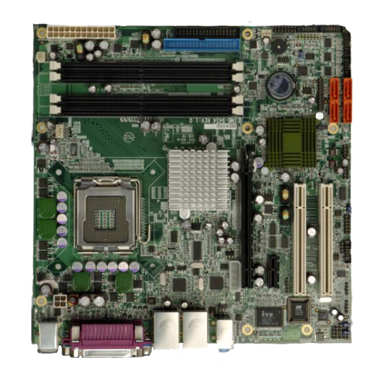
IEI Technology IMB-9454G-R20 User Manual (172 pages)
Brand:
IEI Technology
| Category:
Motherboard
| Size: 5.56 MB
Table of Contents
Table of Contents
3
1 Introduction
15
Imb-9454G Overview
16
IMB-9454G Applications
16
IMB-9454G Benefits
16
IMB-9454G Features
17
Imb-9454G Board Overview
17
Figure 1-1: IMB-9454G Board Overview (Top View)
17
IMB-9454G Connectors
18
Technical Specifications
19
Table 1-1: Technical Specifications
20
2 Detailed Specifications
21
Overview
22
Dimensions
22
Board Dimensions
22
Figure 2-1: IMB-9454G Dimensions (MM)
22
Cpu Support
23
Intel ® Core™2 Duo
23
Table-2-1: Supported Cpus
23
Intel ® Pentium ® D
24
Intel ® Pentium ® 4
24
Intel ® Celeron ® D
24
On-Board Chipsets
25
Intel 945G Northbridge Chipset
25
Northbridge and Southbridge Chipsets
25
Intel ICH7 Southbridge Chipset
26
Graphics Support
26
Memory Support
27
Pci Bus Interface Support
27
Gbe Ethernet
27
Drive Interfaces
28
Floppy Disk Drive (FDD)
28
IDE Interfaces
28
SATA Drives
28
Serial Ports
28
Real Time Clock
29
Infrared Data Association (Irda) Interface
29
Usb Interfaces
29
Bios
29
Operating Temperature and Temperature Control
29
Audio Codec
30
Power Consumption
31
Packaged Contents and Optional Accessory Items
31
Package Contents
31
Figure 2-2: External Interface Panel Dimensions (MM)
23
External Interface Panel Dimensions
23
Table 2-2: Power Consumption
31
Optional Accessory Items
32
3 Connectors and Jumpers
33
Peripheral Interface Connectors
34
IMB-9454G Layout
34
Figure 3-1: Connector and Jumper Locations
34
Peripheral Interface Connectors
35
Rear Panel Connectors
36
Table 3-1: Peripheral Interface Connectors
36
Internal Peripheral Connectors
37
Audio Connector
37
Table 3-2: Rear Panel Connectors
37
On-Board Jumpers
37
Table 3-3: On-Board Jumpers
37
Figure 3-2: Audio Connector Location
38
Table 3-4: Audio Connector Pinouts
38
Audio CD-In Connector
39
Figure 3-3: Audio CD-In Connector Location
39
Table 3-5: Audio CD-In Connector Pinouts
39
Audio AUX-In Connector
40
CPU 12V Power Connector
40
Figure 3-4: Audio AUX-In Connector Location
40
Table 3-6: Audio AUX-In Connector Pinouts
40
Fan Connectors
41
Figure 3-5: CPU 12V Power Connector Location
41
Table 3-7: CPU 12V Power Connector Pinouts
41
Figure 3-6: Fan Connector Locations
42
Table 3-8: CPU Fan Connector Pinouts
42
Table 3-9: System Fan Connector Pinouts
42
FDD Connector
43
Figure 3-7: FDD Connector Connector Location
43
Front Panel Audio Connector
44
Table 3-10: FDD Connector Pinouts
44
Figure 3-8: Front Panel Audio Connector Location
45
Front Panel Connector
45
Table 3-11: Front Panel Audio Connector Pinouts
45
Figure 3-9: Front Panel Connector Location
46
Table 3-12: Front Panel Connector Pinouts
46
Figure 3-10: GPIO Connector Location
47
GPIO Connector
47
Table 3-13: GPIO Connector Pinouts
47
Figure 3-11: IDE Device Connector Location
48
IDE Connector
48
IR Interface Connector
49
Table 3-14: IDE Connector Pinouts
49
Figure 3-12: IR Connector Location
50
PCI Express X1 Slot
50
Table 3-15: IR Connector Pinouts
50
Figure 3-13: PCI Express X1 Slot Locations
51
PCI Express X16 Slot
52
Table 3-16: PCI Express X1 Slot Pinouts
52
Figure 3-14: PCI Express X16 Slot Location
53
Table 3-17: Pcie X16 Side a Pinouts
54
Table 3-18: Pcie X16 Side B Pinouts
54
Figure 3-15: Pcie X16 Power Connector Location
55
PCI Express Power Connector
55
Figure 3-16: Power Connector Location
56
Power Connector
56
Table 3-19: Pcie X16 Power Connector Pinouts
56
RS-422/485 Connector
57
Table 3-20: Power Connector Pinouts
57
Figure 3-17: RS-422/485 Connector Location
58
Serial Port Connectors
58
Table 3-21: RS-422/485 Connector Pinouts
58
Figure 3-18: Serial Port Connector Locations
59
SATA Drive Connectors
59
Table 3-22: COM2 COM3, COM4, COM5 and COM6 Pinouts
59
Figure 3-19: SATA Drive Connector Locations
60
SPDIF Connector
60
Table 3-23: SATA Drive Connector Pinouts
60
Figure 3-20: SPDIF Connector Locations
61
Table 3-24: SPDIF Pinouts
61
Figure 3-21: TPM Connector Location
62
TPM Connector
62
Figure 3-22: Internal USB Connector Locations
63
Internal USB Connectors
63
Table 3-25: TPM Connector Pinouts
63
External Interface Connectors
64
Figure 3-23: IMB-9454G External Interface Connectors
64
Table 3-26: USB3 and USB4 Pinouts
64
Audio Connectors
65
CRT Connector
65
Figure 3-24: Audio Connector
65
Ethernet Connectors
66
Table 3-27: VGA Connector Pinouts
66
Keyboard/Mouse Connector
67
Figure 3-25: VGA Connector
66
Table 3-28: LAN1 and LAN2 Pinouts
67
Table 3-29: RJ-45 Ethernet Connector Leds
67
Serial Port Connectors
68
Figure 3-26: RJ-45 Ethernet Connector
67
Figure 3-27: PS/2 Pinouts
68
Table 3-30: PS/2 Connector Pinouts
68
Parallel Port Connector
69
Figure 3-28: External Serial Port Connector
69
Table 3-31: External Serial Port Pinouts
69
USB Connector
70
Figure 3-29 Parallel Port Connector Pinout Locations
70
Table 3-32: Parallel Port Connector Pinouts
70
Table 3-33: External USB Connector Pinouts
71
This Page Is Intentionally Left Blank
72
4 Installation and Configuration
73
Anti-Static Precautions
74
Installation Considerations
74
Installation Notices
74
Unpacking
75
Unpacking Precautions
75
Checklist
76
Imb-9454G Motherboard Installation
76
Socket Lga775 Cpu Installation
77
CPU Installation
77
CPU Selection: HT Functionality Requirements
77
Socket LGA775 Cooling Kit (CF-520) Installation
80
Figure 4-1: Intel LGA775 Socket
78
Figure 4-2: Remove the CPU Socket Protective Shield
79
Figure 4-3: Open the CPU Socket Load Plate
79
Figure 4-4: Insert the Socket LGA775 CPU
80
Figure 4-5: IEI LGA-775 Cooling Kit
81
Figure 4-6: Securing the Heat Sink to the PCB Board
82
DIMM Module Installation
83
Purchasing the Memory Module
83
Peripheral Device Connection
84
Figure 4-7: Installing the DIMM Module
84
Figure 4-8: Locking the DIMM Module
84
IDE Disk Drive Connector (IDE1)
85
Table 4-1: IEI Provided Cables
85
Floppy Drive Connector
86
COM Port Connectors
86
Figure 4-9: Connection of IDE Connector
85
Table 4-2: On-Board Jumpers
87
Clear CMOS Jumper
88
Figure 4-10 Jumper
87
On-Board Jumpers
87
Figure 4-11: Jumper Locations
88
COM2 Mode Selection
89
Chassis Installation
89
Table 4-3: Clear CMOS Jumper Settings
89
Table 4-4: JP4 Jumper Settings
89
Rear Panel Connectors
90
Audio Interface
90
Ethernet Connection
90
Keyboard and Mouse Connection
90
LCD Panel Connection
90
Serial Connection
90
USB Connection
90
5 Ami Bios Setup
91
Introduction
92
Starting Setup
92
Using Setup
92
BIOS Menu Bar
93
Getting Help
93
Unable to Reboot after Configuration Changes
93
Main
93
Table 5-1: BIOS Navigation Keys
93
System Overview
94
BIOS Menu 1: Main
94
Advanced
95
CPU Configuration
96
IDE Configuration
97
ATA/IDE Configuration [Compatible]
98
BIOS Menu 4: IDE Configuration
98
IDE Master, IDE Slave
99
Legacy IDE Channels [SATA Pri, PATA Sec]
99
IDE Master and IDE Slave
99
Auto-Detected Drive Parameters
100
BIOS Menu 5: IDE Master and IDE Slave Configuration
100
Type [Auto]
101
Zip
101
Lba/Large Mode [Auto]
101
Block (Multi Sector Transfer) [Auto]
102
PIO Mode [Auto]
102
Floppy Configuration
103
DMA Mode [Auto]
103
Auto]
103
32Bit Data Transfer [Enabled]
103
Floppy a [1.44 MB 3½"]
104
Super IO Configuration
104
Serial Port1 Address [3F8/IRQ4]
105
Serial Port1 Mode [Normal]
105
BIOS Menu 7: Super IO Configuration
105
Serial Port2 Address [2F8/IRQ3]
106
Serial Port2 Mode [Normal]
106
Parallel Port Address [378]
106
Parallel Port Mode [Normal]
107
Parallel Port IRQ [IRQ7]
107
Serial Port3 Address [3E8]
108
Serial Port3 IRQ [11]
108
Serial Port4 Address [2E8]
108
Serial Port4 IRQ [10]
108
Serial Port5 Address [2F0]
109
Serial Port5 IRQ [11]
109
Serial Port6 Address [2E0]
109
Serial Port6 IRQ [10]
109
Hardware Health Configuration
110
FAN 1 Mode Setting: [Full On]
110
Temperature 1 Limit of off
110
Temperature 1 Limit of Start
111
Temperature 1 Limit of Full
111
Fan 1 Start PWM
111
Slop PWM 1
111
FAN 2 Mode Setting: [Full On]
111
Temperature 2 Limit of off
111
Temperature 2 Limit of Start
111
Temperature 2 Limit of Full
111
Fan 2 Start PWM
111
Slop PWM 2
111
ACPI Configuration
112
Temperature 3 Limit of Start
112
Temperature 3 Limit of Full
112
Fan 3 Start PWM
112
Slop PWM 3
112
General ACPI Configuration
113
ACPI Aware O/S [Yes]
113
APM Configuration
114
Suspend Mode [S1 (POS)]
114
Power Management/Apm [Enabled]
115
Power Button Mode [On/Off]
115
BIOS Menu 11: APM Configuration
115
Restore on AC Power Loss [Last State]
116
Resume on Ring [Enabled]
116
Resume on PME# [Enabled]
116
MPS Configuration
117
Resume on RTC Alarm [Disabled]
117
RTC Alarm Date (Days)
117
System Time
117
Resume on PCI-Express WAKE# [Enabled]
117
USB Configuration
118
MPS Revision [1.4]
118
USB Configuration
119
USB Devices Enabled
119
USB Function [8 USB Ports]
119
BIOS Menu 13: USB Configuration
119
USB 2.0 Controller [Enabled]
120
Legacy USB Support [Enabled]
120
USB2.0 Controller Mode [Hispeed]
120
USB Mass Storage Device Configuration
121
Boot
121
Device
121
Boot Settings Configuration
122
Quick Boot [Enabled]
123
Quiet Boot [Disabled]
123
BIOS Menu 16: Boot Settings Configuration
123
Addon ROM Display Mode [Force BIOS]
124
Bootup Num-Lock [On]
124
Display System Configuration [Disabled]
124
Boot Device Priority
125
Boot from LAN Support [Disabled]
125
Hard Disk Drives
126
Removable Drives
126
CD/DVD Drives
127
Security
128
Change Supervisor Password
128
Chipset
129
Change User Password
129
Audio Controller [AC'97 Audio Only]
130
Onboard LAN1 [Enabled]
130
BIOS Menu 20: Chipset
130
North Bridge Configuration
131
Onboard LAN2 [Enabled]
131
DRAM Frequency [Auto]
131
Configure DRAM Timing by SPD [Enabled]
132
Memory Hole [Disabled]
132
Exit
133
Internal Graphics Mode Select [Enable, 8MB]
133
Save Changes and Exit
134
Discard Changes and Exit
134
Discard Changes
134
Load Optimal Defaults
134
Load Failsafe Defaults
134
6 Software Drivers
135
Available Software Drivers
136
Chipset Driver Installation
136
Figure 6-1: Installshield Wizard Preparation Screen
137
Figure 6-2: Welcome Screen
137
Figure 6-3: License Agreement
138
Figure 6-4: Readme Information
138
Vga Driver
139
Figure 6-5: Restart the Computer
139
Figure 6-6: Starting Install Shield Wizard Screen
140
Figure 6-7: Preparing Setup Screen
140
Figure 6-8: VGA Driver Installation Welcome Screen
141
Figure 6-9: VGA Driver License Agreement
141
Figure 6-10: VGA Driver Installing Notice
142
Figure 6-11: VGA Driver Installation Complete
142
Broadcom LAN Driver (for Gbe LAN) Installation
143
Figure 6-12: Access Windows Control Panel
143
Figure 6-13: Double Click the System Icon
144
Figure 6-14: Double Click the Device Manager Tab
144
Figure 6-15: Device Manager List
145
Figure 6-16: Search for Suitable Driver
145
Figure 6-17: Locate Driver Files
146
Figure 6-18: Location Browsing Window
146
Realtek Audio Driver (ALC655) Installation
147
Figure 6-19: Installshield Wizard Extracting Files
147
Figure 6-20: Audio Driver Install Shield Wizard Starting
148
Figure 6-21: Audio Driver Setup Preparation
148
Figure 6-22: Audio Driver Digital Signal
149
Figure 6-23: Audio Driver Installation Continues
149
Intel Matrix Storage Manager Installation
150
Figure 6-24: Audio Driver Installation Complete
150
Figure 6-25: Preparing Setup Screen
151
Abios Configuration Options
153
Bios Configuration Options
153
A.1 BIOS Configuration Options
154
O Ptions
154
Bwatchdog Timer
157
Caddress Mapping
161
Io Address Map
162
St Mb Memory Ddress Ap
162
Addres Map
162
Irq Mapping Table
163
Dma Channel Assignments
163
Dexternal Ac'97 Audio Codec
165
Introduction
166
Accessing the AC'97 CODEC
166
D.1 I Ntroduction
166
Driver Installation
166
Sound Effect Configuration
167
Accessing the Sound Effects Manager
167
Sound Effect Manager Configuration Options
168
Eindex
171
Advertisement
Advertisement
Related Products
IEI Technology IMB-9452
IEI Technology IMB-9454G-R40
IEI Technology IMBA-Q670
IEI Technology IMBA-XQ354
IEI Technology IMBA-8650
IEI Technology IMBA-9654
IEI Technology IMB-X63 Series
IEI Technology IMBA-BDE-1518-R10
IEI Technology IMBA-Q370
IEI Technology IMBA-KX
IEI Technology Categories
Motherboard
Touch Panel
Computer Hardware
Single board computers
Desktop
More IEI Technology Manuals
Login
Sign In
OR
Sign in with Facebook
Sign in with Google
Upload manual
Upload from disk
Upload from URL