Table of Contents
Advertisement
Quick Links
FUSION
illuminators installation guide
This installation guide provides instructions for installing the RAYMAX
and RAYLUX FUSION series illuminators
Installation Steps
1. Mount Illuminator
2. Connect Illuminator to low voltage
power supply
3. Input 12-24V DC/ 24V AC
4. Adjust Power to alter light intensity
5. Adjust Photocell sensitivity
6. Photocell following contact
RM/RL F 100 Setup
7. Telemetry input and photocell
following contact
Set Up Steps
1. Position illuminator adjacent to
camera and point towards scene
2. Adjust vertical and horizontal
position of lamp to ensure full field
of view illuminated
3. Tighten all fixings
Package Contents
1. Illuminator including mounting
bracket
(RM/RL F 100 only, includes
additional wiring loom)
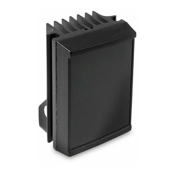
Overview
RAYMAX / RAYLUX
FUSION illuminator
GOLDeN RULeS:
• Ensure operating voltage is
correct for unit being installed
(12-24V DC/ 24V AC)
www.rayteccctv.com
Advertisement
Table of Contents

Related Manuals for Raytec RL F 25


Summary of Contents for Raytec RL F 25
- Page 1 FUSION illuminators installation guide This installation guide provides instructions for installing the RAYMAX and RAYLUX FUSION series illuminators Installation Steps Overview 1. Mount Illuminator 2. Connect Illuminator to low voltage power supply 3. Input 12-24V DC/ 24V AC Optional Set-up (if required) 4.
- Page 2 Bracket LeD illuminator Back of Unit Cables RM/RL F 25 & 50 ‘Command and Control’ Technology™ 1x four core cable RM/RL F 25 & 50 Black wire Red wire Orange and Brown wires= Photocell following contact. Volt free output. Non polarity sensitive.
- Page 3 Made in UK Photocell following contact, volt free relay contact - normally open (day) to normally closed (night). RM/RL F 25 & 50 only Orange and brown wires = Photocell following contact RM/RL F 100 only RM/RL F 100 only: Telemetry input and photocell following contact.
- Page 4 Set Up TARGeT Position illuminator adjacent to Adjust vertical and horizontal camera and point towards scene position of lamp to ensure full field (Optional night set-up for of view illuminated optimum image performance) Tighten all fixings Match illumination to camera field of view Camera Camera Light...
- Page 5 (Not to scale) Standard Bracketry 25mm 12.5mm 36mm (1”) 25mm (0.5”) (1.4”) (1”) 47mm 72mm (2.8”) (1.9”) RM/RL F 25 RM/RL F 50 52mm (2”) 104.5mm 25mm (4.1”) (1”) RM/RL F 100 Optional Bracketry Pole Mount Wall Mount Ptz Mount Dome Mount...
- Page 6 75 x 100 x 54mm L x W x D (7 x 5.3 x 2.5”) (5.3 x 4 x 2.5”) (3 x 4 x 2”) Integrated Command and Control™ Technology RM/RL F 25/50 RM/RL F 100 • Inbuilt photocell for automatic on/off • Inbuilt photocell for automatic on/off operation operation • Inbuilt power adjust...
-
Page 7: Trouble Shooting
Step 3: Set-up Camera, lens and illumination • Check alignment of lamp • Check camera lens – fully open at night & set correctly • Check model number to Raytec performance specification to ensure required distance is achievable Step 4: Call Raytec for further assistance Note down: • Model and serial number of illuminator • Camera make and model • Lens make and model If the Raytec lamp is still not delivering the required performance, please contact us for further assistance. - Page 8 UK / Europe T: +44 (0) 1670 520055 F: +44 (0) 1670 819760 sales@rayteccctv.com Americas (Toll Free) T: +1 888 505 8335 ussales@rayteccctv.com www.rayteccctv.com...
Need help?
Do you have a question about the RL F 25 and is the answer not in the manual?
Questions and answers