Advertisement
Quick Links
Installation and Setup Guide
Installation by suitably trained and qualified personnel only
Suitable for Internal and External Applications
Box Contents:
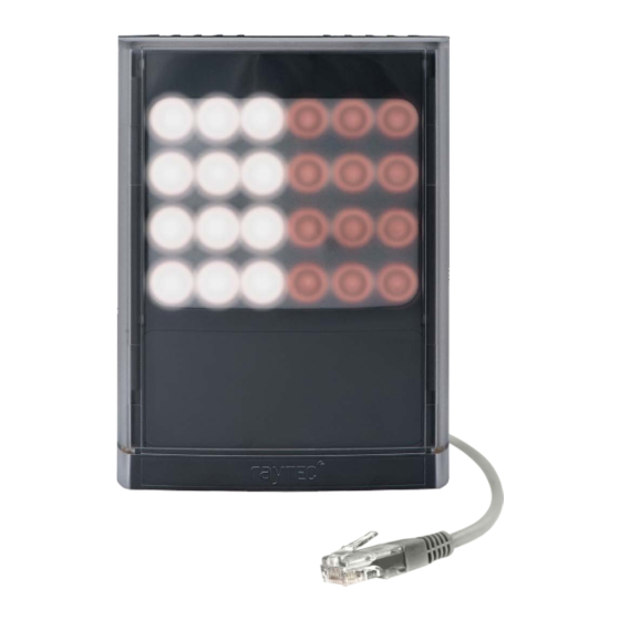
VARIO2 IPPOE Hybrid Illuminator - Infra-Red (IR) & White-Light (WL)
35° x 10° beam angle IHD
60° x 25° beam angle IHD
Waterproof RJ45 connector
Accessories (optional):
80° x 30° beam angle IHD
120° x 50° beam angle IHD
System requirements: PC running Windows 7 with IE9 (or equivalent) and network access.
Advertisement

Related Manuals for Raytec vario2ip HYBRID


Summary of Contents for Raytec vario2ip HYBRID
- Page 1 Installation and Setup Guide Installation by suitably trained and qualified personnel only Suitable for Internal and External Applications Box Contents: VARIO2 IPPOE Hybrid Illuminator - Infra-Red (IR) & White-Light (WL) 35° x 10° beam angle IHD 60° x 25° beam angle IHD Waterproof RJ45 connector Accessories (optional): 80°...
-
Page 2: Safety Information
Safety Information Install in a well ventilated area. Eye Safety : IR Light (850nm and 940nm) Caution – IR emitted from this product EN62471 Risk Group 2. Do not stare at the lamp. Avoid exposure or use appropriate shielding / eye protection. -
Page 3: Product Introduction
LED technology in the same illuminator package. The Vario2 IPPOE Hybrid is designed to connect to a suitable network and is provided with an integrated Web Interface. The Raytec Discovery Tool allows for easy identification and connection to the illuminator or you can connect directly to the illuminator via its IP address. - Page 4 Hard Reset Button Please note: base plate has been removed for Interchangeable PoE Detection Resistance illustrative purposes. Lensing Selection Switch Photocell Auxiliary Cable Optional 24V DC power input – red (+ve) & black (-ve) External Input, volt free or TTL – orange (TTL +ve) &...
-
Page 5: Basic Steps
STEP 3: Physical Installation (Pg. 9-10) Adjust interchangeable lens if required. Fix to wall, pole or camera unit using U bracket provided or other Raytec bracketry. IMPORTANT: Ensure illuminator is rated to provide required viewing distances and select correct angle... - Page 6 IP address. IMPORTANT: We recommend Raytec Discovery Tool as the easiest way to establish communication. If using IP address for direct communication, illuminator and computer must be in same network range. STEP 5: Illuminator Set-Up (Pg.
- Page 7 Wiring The illuminator is supplied with a terminated CAT 5 cable with a waterproof Ethernet connector (supplied loose i.e. not fitted) and an auxiliary multi-core cable. Option 1 – Power via PoE Connect an Ethernet cable (category 5 or better) using the T-568B wiring standard between the Power Sourcing Equipment (PSE) and the illuminator.
- Page 8 PoE Detection – Resistance Selection Switch There is a switch on the VAR2-IPPOE-hy8-1 and hy8-1-C illuminators which can be used to change the PoE detection resistance of the illuminator (24.9KΩ is the factory default setting). Turn the power to the illuminator OFF, remove the baseplate and access the switch as shown. The majority of PSE equipment requires a detection resistance of 24.9KΩ...
- Page 9 Interchangeable Lenses: Changing the Angle Step 2 Step 3 Step 4 Step 1 Remove baseplate Remove / Replace Replace baseplate Unscrew baseplate & tighten diffuser lens The illuminator is delivered with a 35° beam angle. To alter to 10 , remove the baseplate from the bottom of the product and remove the existing lens and then re-attach the baseplate securely.
- Page 10 Vario2 IPPOE Hybrid is delivered as standard with a bracket at the bottom of the unit. This can be moved to the top of the unit if required. Attach illuminator to wall, housing or pole using U-bracket provided or dedicated Raytec bracketry.
- Page 11 IP address. This free application is downloadable from our website or please contact Raytec. To change the IP address using the Raytec Discovery Tool so that you can communicate with the illuminator(s) you can: Use DHCP Run the Raytec Discovery Tool.
- Page 12 The illuminator responds to multicast messages - and therefore does not need to have a valid IP address in the same network range for the Raytec Discovery Tool to find it. But it does require a valid IP address for connection and communication. ALL IP addresses need to reside within the same network address range to ensure these components can communicate with each other.
- Page 13 Local, HTTP + Local or VMS + Local. To operate the illuminator via a VMS or third party application that uses the Raytec API, then the illuminator mode should be set to VMS or VMS + Local. In VMS mode the illuminator will ignore Photocell and External Input triggers and respond only to valid VMS commands.
- Page 14 VMS integration allows the illuminator(s) to be directly controlled and triggered by events within the VMS environment such as scheduled events, alarm triggers, camera commands, etc. HTTP Integration allows the illuminator to be directly controlled and triggered on receipt of valid HTTP commands generated on the network from VMS, cameras or other components capable of generating HTTP commands.
- Page 15 Advanced Settings Manual Override Countdown Duration = 30 mins External Input External Output Type of Input = Volt Free Trigger State = Photocell Only Active State = Short Circuit / Low Active State = Short Circuit / Low Photocell Photocell Sensitivity = 20 lux Basic Web Page Functionality All web pages have the following information in the header bar Model Type / Lamp Name / Group Name...
- Page 16 User has access to Home Page and Diagnostics pages. Administrator has access to all pages.
- Page 17 Page Name Functions available Home Page Allows manual control of an individual illuminator or group of illuminators including power adjustment, wavelength choice and deterrent controls. Select override to operate above functions. Settings / Groups Allows detailed set-up and configuration of the illuminator including how it responds to Photocell and External Inputs, light type, duration on period, power levels, soft start, response to group commands, deterrent patterns and speeds.
- Page 18 Illuminator web interface note You may see the model name of your illuminator cut short on the home page of your illuminator like below: Due to a change to the format of our model names, the size of the illuminator details box above has been increased.
- Page 19 T-568B wiring standard. If the illuminators are correctly wired to the network, run the Raytec Discovery Tool and try to discover the illuminator on the network. If the illuminator is discovered and the “State” indicator is grey, this indicates that there is no communications with the illuminator.
Need help?
Do you have a question about the vario2ip HYBRID and is the answer not in the manual?
Questions and answers