Table of Contents
Advertisement
Quick Links
Full Installation and Setup Guide
VARIO2 IPPoE Series
Installation by suitably trained and qualified personnel only
Suitable for Internal and External Applications
Box Contents:
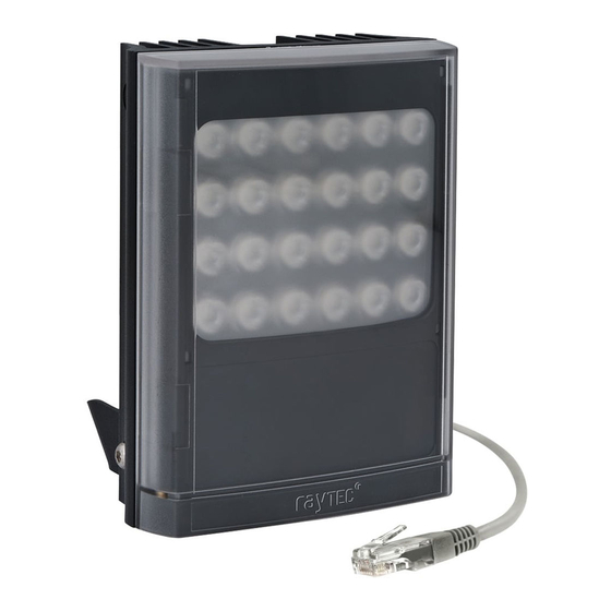
VARIO2 IP PoE Illuminator - Infra-Red (IR) or White-Light (WL)
35° x 10° beam angle IHD
60° x 25° beam angle IHD
Waterproof RJ45 connector
Accessories (optional):
80° x 30° beam angle IHD
120° x 50° beam angle IHD
System requirements: PC running Windows 7 with IE9 (or equivalent) and network
access.
1
Advertisement
Table of Contents

Subscribe to Our Youtube Channel
Related Manuals for Raytec VAR2 IPPOE i4-1


Summary of Contents for Raytec VAR2 IPPOE i4-1
-
Page 1: Box Contents
Full Installation and Setup Guide VARIO2 IPPoE Series Installation by suitably trained and qualified personnel only Suitable for Internal and External Applications Box Contents: VARIO2 IP PoE Illuminator - Infra-Red (IR) or White-Light (WL) 35° x 10° beam angle IHD 60°... -
Page 2: Product Introduction
VARIO2 IP PoE is a Network Illuminator designed to connect to a suitable network and is provided with an integrated Web Interface. The Raytec Discovery Tool allows for easy identification and connection to the illuminator or you can connect directly to the illuminator via its IP address. - Page 3 Please note: base Interchangeable Hard Reset plate has been Lensing Button removed for PoE Detection illustrative purposes. Resistance Selection Switch Photocell Auxiliary Cable Optional 24V DC power input – red (+ve) & black Please note: Waterproof (-ve) connector is supplied loose – and External Input, volt free or TTL –...
-
Page 4: Basic Steps
STEP 3: Physical Installation (Pg. 8-9) Adjust interchangeable lens if required. Fix to wall, pole or camera unit using U bracket provided or other Raytec bracketry. IMPORTANT: Ensure illuminator is rated to provide required viewing distances and select correct angle... - Page 5 We recommend the easiest and fastest way to identify and connect to illuminators is using the Raytec Discovery Tool where the IP address can be altered or DHCP enabled. Alternatively, type the IP address of illuminator into a web browser – default is 192.168.2.80 –...
-
Page 6: Wiring
Wiring The illuminator is supplied with a terminated CAT 5 cable with a waterproof Ethernet connector (supplied loose i.e. not fitted) and an auxiliary multi-core cable. Option 1 – Power via PoE Connect an Ethernet cable (category 5 or better) using the T-568B wiring standard between the Power Sourcing Equipment (PSE) and the illuminator. -
Page 7: Poe Detection - Resistance Selection Switch
Colour Description Wire Gauge (AWG) Orange External Input -Volt free or TTL +ve Purple External Input -Volt free or TTL GND Yellow External Output – Volt free White External Output - Volt free WARNING: To maintain the IP rating of the product the multi-core auxiliary cable must be waterproofed and terminated appropriately even if it is not in use. -
Page 8: Interchangeable Lenses: Changing The Angle
VARIO2 IP PoE is delivered as standard with a bracket at the bottom of the unit. This can be moved to the top of the unit if required. Attach illuminator to wall, housing or pole using U-bracket provided or dedicated Raytec bracketry. - Page 9 Notes : Unit can alternatively be powered by 24V DC if required Multi-core auxiliary cable also fitted to unit Use for alternative power (24V DC) if required Use for connecting external input and external output as required To maintain the IP rating of the product, any cable not in use must be waterproofed and terminated appropriately.
-
Page 10: Connecting To The Network
We recommend the easiest and fastest way to identify and connect to illuminators is using the Raytec Discovery Tool where the IP address can be altered or DHCP enabled. Using the Raytec Discovery Tool avoids the need to have the computer and illuminator in the same network range in order to alter the IP address. -
Page 11: Raytec Discovery Tool Basics
The illuminator responds to multicast messages - and therefore does not need to have a valid IP address in the same network range for the Raytec Discovery Tool to find it. But it does require a valid IP address for connection and communication. ALL... - Page 12 Discover With the VARIO2 IPPoE powered and attached to the same network, press and the Raytec Discovery Tool will display a list of illuminators available on the network. See instructions above on how to change IP address or enable DHCP in order to allow communication with the illuminator.
-
Page 13: Hierarchy Of Photocell Vs. Telemetry
Hierarchy of Photocell vs. Telemetry If the telemetry function is enabled, then the photocell must detect that it is dark for the telemetry function to operate. The photocell overrides the telemetry function during the day. If the external input/telemetry function needs to be operated 24 / 7, then the photocell function should be disabled from the settings / groups page. - Page 14 Override is only available when the illuminator mode is set to HTTP + Local VMS + Local To operate the illuminator via a VMS or third party application that uses the Raytec VMS + Local. API, then the illuminator mode should be set to...
-
Page 15: Factory Defaults
The External Input will activate the illuminator at 100% (NOT soft start) for the duration of the input provided the photocell detects it is dark. External Output: activated by photocell and will become short circuit when active. Factory Defaults Name VARIO2 IP Group Name <<Deliberately Left Blank>>... -
Page 16: Basic Web Page Functionality
Advanced Settings Manual Override Photocell Sensitivity = 20 lux Countdown Duration = 30 mins External Input External Output Type of Input = Volt Free Trigger State = Photocell Only Active State = Short Circuit / Low Active State = Short Circuit / Low Basic Web Page Functionality All web pages have the following information in the header bar Model Type / Lamp Name / Group Name... - Page 17 User has access to Home Page and Diagnostics pages. Admin has access to all pages.
- Page 18 Page Name Functions available Home Page Allows manual control of an individual illuminator or group of illuminators including power adjustment, boost and deterrent controls. Select override to operate above functions. Settings / Groups Allows detailed set-up configuration illuminator including how it responds to Photocell and External Inputs, duration on period, power levels, soft start, response to group commands, deterrent patterns and speeds.
-
Page 19: Illuminator Web Interface Note
Illuminator web interface note You may see the model name of your illuminator cut short on the home page of your illuminator like below: Due to a change to the format of our model names, the size of the illuminator details box above has been increased. -
Page 20: Ping
Ping The illuminator will respond to a standard Ping command sent to its valid IP address. For the ping command to work the illuminator and computer must reside in the same network range. Basic Troubleshoot Check if the camera and illuminator are aligned correctly. ... - Page 21 If the illuminators are correctly wired to the network, run the Raytec Discovery Tool and try to discover the illuminator on the network. If the illuminator is discovered and the “State” indicator is grey, this indicates that there is no communications with the illuminator. Ensure IP Address and Subnet Mask of computer and illuminator are set within the same range.
-
Page 22: Table Of Contents
Log-in, Security & Basic Illuminator Setup ................13 Factory Defaults ..........................15 Basic Web Page Functionality ....................... 16 Illuminator web interface note ..................... 19 Ping ................................ 20 Basic Troubleshoot ........................... 20 Raytec Discovery Tool in Depth ....................... 25 Network Settings ..........................26... - Page 23 DHCP – Automatic allocation of IP address ................27 Static Network Configuration – Manual allocation of IP address ........28 Name and Group Name ......................... 29 lluminator Status ..........................31 Other Information ..........................31 Unit Details – Parameters ....................... 32 Detailed Illuminator Setup: Web Interface Pages ..............
- Page 24 Reboot / Restart Illuminator ......................55 Diagnostics .............................. 56 Advanced Diagnostics ......................... 57 Software Update ............................ 58 Log Off ..............................60 Hard Reset Button – Located on illuminator ................61 Raytec APIs (VMS and HTTP) ......................62 Troubleshooting & FAQs ........................62...
-
Page 25: Raytec Discovery Tool In Depth
The illuminator responds to multicast messages - and therefore does not need to have a valid IP address in the same network range for the Raytec Discovery Tool to find it. But it does require a valid IP address for connection and communication. -
Page 26: Network Settings
See the illuminators status See whether the illuminator is ON / OFF View the MAC address of each illuminator Change Network Settings Change the Name and Group Name See additional illuminator details including name, firmware version, model and ... -
Page 27: Dhcp - Automatic Allocation Of Ip Address
Raytec Discovery Tool by pressing . The illuminators IP address should automatically be updated into the required range and the illuminator can now be accessed directly from the Raytec Discovery Tool by double clicking on the illuminator from the list of discovered illuminators. -
Page 28: Static Network Configuration - Manual Allocation Of Ip Address
IP Addresses issued are unique and not repeated. Enter the Use the following IP appropriate IP Address and Subnet Mask having selected address and press The unit will now be allocated the IP Address as entered. Refresh the Raytec Discover Discovery Tool by pressing... -
Page 29: Name And Group Name
Both “Name” and “Group Name” can be modified directly from the Raytec Discovery Tool or via the web interface. To change these via the Raytec Discovery Tool, highlight the illuminator you want to Status change. Then press... - Page 30 “Unit Name” and “Group Name”can both be edited by entering a new value in their fields.
-
Page 31: Lluminator Status
After the change has been made save the edited names by pressing The selected unit name and group have now been changed. Refresh the Raytec Discover Discovery Tool by pressing and the updated information should be displayed. lluminator Status The Raytec Discovery Tool has two status indicators for each illuminator. The colours... -
Page 32: Unit Details - Parameters
Selecting the Parameters button within the “Unit Details” screen provides a high level of detailed information regarding the performance and operation of the illuminator. This is designed to be used during technical support of the illuminator with Raytec or your supplier. -
Page 33: Detailed Illuminator Setup: Web Interface Pages
Log-In Page Access Log-In Page for individual illuminator by double-clicking on the illuminator from the Raytec Discovery Tool or by typing the IP address into the web browser. User Names & Passwords are case sensitive. (Max 32 characters – alphanumeric,... -
Page 34: Home Page
User User name Password Operator user password Administrator admin password Forgotten Password If you are an operator, please request the assistance of the administrator. They can reset the password through the “Access” Web Page. If you are an administrator, you will have to use the Hard Reset button on the illuminator –... - Page 35 A visual representation of the product and its current state (ON or OFF) Product Type & Model Product Name - if a name has been assigned (using Network Page or Raytec Discovery Tool) Group Name - if a name has been assigned (using Settings / Group Page or Raytec Discovery Tool) Trig –...
- Page 36 Important - If an illuminator is in group override control from another illuminator you will not be able to access the override control on that illuminator. Boost & Group Boost This will boost the individual illuminator or all illuminators in the group (if GROUP BOOST selected) to 110% of normal output power for a period of 10 seconds.
-
Page 37: Settings / Groups
Settings / Groups This page is used to configure the operation of the illuminator based on Photocell and / or External Inputs, configure the illuminator to operate in Local, VMS or HTTP mode, assign the illuminator to a Group and configure the deterrent mode of the illuminator. -
Page 38: Illuminator Mode
SAVE WARNING: For changes to take effect, the button must be pressed Override WARNING: You cannot see the effect of your changes if the button on the Home Page is still active (green) or your illuminator is in group Override control from another illuminator Illuminator Mode The illuminator can be operated in five different modes:... - Page 39 2. VMS The illuminator will respond ONLY to third party VMS systems and any applications that use the Raytec API. The illuminator will NOT respond to photocell and telemetry events. The user CANNOT take direct manual override control through the web interface.
-
Page 40: Groups
There is a RaytecAPIInstaller.exe and a Raytec API Quick Start guide available to support VMS integration. HTTP Options – Additional Information : There is a Raytec HTTP Command Summary guide and a Raytec HTTP API guide available to support HTTP integration. Groups The VARIO2 IP PoE illuminator is configured so that it can work individually or as part of a group of illuminators. -
Page 41: Group Name
One illuminators External Input trigger can turn all illuminators in the group ON (E.g. Car park entrance / Alarm) The Group Override function on the Home Page allows the user to take instant control of the group of illuminators all at the same time Group Name An illuminator can be associated with a new or existing group to enable it to follow group commands from the photocell input and / or External Input. -
Page 42: Lamp Mode On Trigger
If Group control is NOT selected from Trigger Control options, then the illuminator will not respond to any Group commands. If Group Control is selected from Trigger Control options, then the user can select two modes of operation in response to Group Commands: 1. -
Page 43: Power
Factory Defaults: Photocell External Input Power This dictates the power level that the illuminator turns on at in response to a valid instruction. Power levels can be set from 20% to 100% using the slider bar. Factory Defaults: Photocell 100% External Input 100% Duration... -
Page 44: Soft Start
period and it will have the effect of restarting the timer. The illuminator will stay ON until the end of the timed period even if the illuminators photocell states it is daylight. Min and Max timer settings are: Photocell Min: 30 mins External Input Min: 1 mins Photocell Max:... - Page 45 Traditional SOS pattern 3 short on/off, 3 longer on/off, 3 short on/off Wave The illuminator slowly ramps up and down from 100% to 20% Hi-Lo The illuminator alternates between 100% and 20% power Factory Default: There are 3 selectable deterrent speeds available; Slow, Medium, Fast Factory Default: Slow...
-
Page 46: Advanced Settings
Advanced Settings This page is used to further configure the operation of the illuminator based on more detailed requirements of the Photocell, External Input, External Output and to set the duration of the Override Timer. Manual Override - Countdown Duration There are 8 selectable durations from a drop down list for the Countdown Duration of the Manual Override feature on the Home Page. -
Page 47: External Input - Select Type Of Input & Active State On Input
Factory Default: 30 minutes External Input – Select type of Input & Active State on Input The External Input wires will accept either volt free or TTL inputs – see polarity on wiring instructions on page 6. The correct type of input must be selected from the drop down list to match the input to ensure correct operation. -
Page 48: Photocell Sensitivity
External Output Trigger State: The drop down box gives you the option to disable the external output signal or make the signal dependant on active states of either the photocell or External Input or a combination of the two. (Photocell Active State = Darkness. -
Page 49: Access / Passwords
Access / Passwords Caution: All passwords are case sensitive. Keep a note of all passwords in a safe place. Defaults: User User name Password Administrator admin password Operator user password Only the Administrator can change passwords. - Page 50 Maximum number of characters: User Name 32 characters – alphanumeric and symbols allowed Passwords 32 characters – alphanumeric and symbols allowed SAVE WARNING: For changes to take effect, the button must be pressed Recovery of Lost Passwords If you are an Operator, please request the assistance of the Administrator. They can reset the password through the “Access”...
-
Page 51: Network
Network This page allows the configuration of the illuminators network settings. The MAC Address is a unique identifier and cannot be changed The Illuminator Name can be changed on this page. Avoid duplicates. Maximum number of characters is 15 – alphanumeric. Enable DHCP You may enable DHCP if your network is compatible and then IP addresses will be allocated automatically without creating duplicates. -
Page 52: Manual Ip Address
Manual IP Address Alternatively, manually change the IP address into a suitable range for your network “Enable DHCP” by unchecking the box. It is vital to avoid duplicate IP addresses. Gateway, Subnet Mask, Primary DNS and Secondary DNS can all be changed on this “Enable DHCP”... - Page 53 Warning: We strongly recommend that IP addresses are changed via the Raytec Discovery Tool. This is the safest way to ensure that the connection to the illuminator is not lost as a result of setting an invalid IP address. All other settings remain unchanged.
-
Page 54: System Information
System Information This page shows basic information about the illuminator including software version, product type, illuminator name and group name. This is for information only and cannot be altered on this page. Restore Factory Settings At any stage, it is possible to restore ALL the original factory settings of the illuminator. -
Page 55: Reboot / Restart Illuminator
Reboot / Restart Illuminator It is also possible to reboot / restart the illuminator. The illuminator will restart using the existing settings of the illuminator. A reboot / restart is generally recommended if a system becomes unresponsive or you want to ensure settings have been reloaded correctly. During the reboot / restart process the illuminator may come on / flash for a short period. -
Page 56: Diagnostics
Diagnostics This page is useful for first level troubleshooting and displays basic diagnostics and information of the illuminator as follows: Input Voltage Status Green LED – Input voltage correctly within specified range Amber LED – Potential fault Check Adv Diagnostics for more information LED Status Green LED –... -
Page 57: Advanced Diagnostics
This page is useful for detailed troubleshooting and displays diagnostics and information about the illuminator. It is intended to be used for detailed troubleshooting with Raytec. Note: Information on this page is NOT constantly updated or refreshed automatically. To refresh the page, press Function Key F5 or select the page again from the... -
Page 58: Software Update
This page indicates the current version of the software / firmware and also enables the software / firmware to be updated over the network. To upload a new version of software / firmware, please contact Raytec to receive the latest version. - Page 59 The update will restart the unit. From software / firmware version 2.0.0 and above, the following settings will remain unchanged: IP Address (if configured statically) DHCP mode Gateway address Subnet mask Primary DNS Secondary DNS ...
-
Page 60: Log Off
Log Off We recommend after using the illuminator web interface that users log off using the Log Off Page. -
Page 61: Hard Reset Button - Located On Illuminator
Release the Reset button. 5. Replace the baseplate securely to ensure unit remains waterproof. The illuminator can now be discovered using the Raytec Discovery Tool and can be configured as normal following the instructions in this manual. Be aware that the IP address will have been restored to factory default, 192.168.2.80. -
Page 62: Raytec Apis (Vms And Http)
Raytec APIs (VMS and HTTP) The Raytec Network Illuminator has been designed such that it can be integrated into party systems such as a VMS, BMS etc. as well as receiving HTTP commands and Raytec have suitable APIs to support such integrations. Please contact Raytec to discuss your particular requirements. - Page 63 – Make I cannot communicate with my illuminator from the Raytec Discovery Tool sure the IP address of the computer and the illuminator are set to the same range to allow communication. The default IP address of the illuminator is 192.168.2.80.
- Page 64 Vario2 IPPOE Instruction Guide Rev 1.0.0 Full...
Need help?
Do you have a question about the VAR2 IPPOE i4-1 and is the answer not in the manual?
Questions and answers