
Related Manuals for Digisol DG-FS4528E


Summary of Contents for Digisol DG-FS4528E
-
Page 1: Installation Guide
Installation Guide MUSTANG 4000 SWITCH SERIES DG-FS4528E INSTALLATION GUIDE V1.0 2013-09-24 As our products undergo continuous development the specifications are subject to change without prior notice... - Page 2 N S T A L L A T I O N UIDE DG-FS4528E L2 F THERNET WITCH Layer 2 Switch with 24 10/100BASE-TX (RJ-45) Ports, and 4 Combination Gigabit (RJ-45/SFP) Ports DG-FS4528E 092013...
-
Page 3: About This Guide
BOUT UIDE URPOSE This guide details the hardware features of the switch, including the physical and performance-related characteristics, and how to install the switch. UDIENCE The guide is intended for use by network administrators who are responsible for installing and setting up network equipment; consequently, it assumes a basic working knowledge of LANs (Local Area Networks). - Page 4 BOUT UIDE EVISION ISTORY This section summarizes the changes in each revision of this guide. 2013 R EVISION This was the first revision of this guide. – 4 –...
-
Page 5: Table Of Contents
ONTENTS BOUT UIDE ONTENTS ABLES IGURES NTRODUCTION Overview Switch Architecture Network Management Options Description of Hardware 10/100BASE-T Ports SFP Slots Port and System Status LEDs Power Supply Socket Application Examples Network Aggregation Plan Remote Connection with Fiber Cable NSTALLING THE WITCH Selecting a Site Ethernet Cabling... -
Page 6: Contents
ONTENTS Installing an Optional SFP Transceiver Connecting to a Power Source Connecting to the Console Port Wiring Map for Serial Cable AKING ETWORK ONNECTIONS Connecting Network Devices Twisted-Pair Devices Cabling Guidelines Connecting to PCs, Servers, Hubs and Switches Network Wiring Connections Fiber Optic SFP Devices Connectivity Rules 1000BASE-T Cable Requirements... - Page 7 ONTENTS Physical Characteristics Switch Features Management Features Standards LOSSARY NDEX – 8 –...
-
Page 8: Tables
ABLES Table 1: Port Status LEDs Table 2: System Status LEDs Table 3: Console Cable Wiring Table 4: Maximum 1000BASE-T Gigabit Ethernet Cable Length Table 5: Maximum 1000BASE-SX Gigabit Ethernet Cable Lengths Table 6: Maximum 1000BASE-LX Gigabit Ethernet Cable Length Table 7: Maximum 1000BASE-LH Gigabit Ethernet Cable Length Table 8:... - Page 9 IGURES Figure 1: Front and Rear Panels Figure 2: Port Status LEDs Figure 3: System Status LED Figure 4: Power Supply Socket Figure 5: Network Aggregation Plan Figure 6: Remote Connections with Fiber Cable Figure 7: RJ-45 Connections Figure 8: Attaching the Brackets Figure 9: Installing the Switch in a Rack...
-
Page 10: Introduction
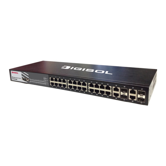
NTRODUCTION VERVIEW The DG-FS4528E switch is a intelligent switch with 24 10/100BASE-T ports, and four Gigabit combination ports that are comprised of an RJ-45 port and an SFP transceiver slot. There is also an SNMP-based management agent embedded on the main board. This agent supports both in-band and out-of-band access for managing the switch. -
Page 11: Switch Architecture
| Introduction HAPTER Description of Hardware WITCH RCHITECTURE This switch employs a wire-speed, non-blocking switching fabric. This permits simultaneous wire-speed transport of multiple packets at low latency on all ports. This switch also features full-duplex capability on all ports, which effectively doubles the bandwidth of each connection. -
Page 12: Sfp Slots
| Introduction HAPTER Description of Hardware Each port also supports auto-negotiation of flow control, so the switch can automatically prevent port buffers from becoming saturated. SFP S LOTS The Small Form Factor Pluggable (SFP) transceiver slots are shared with four RJ- 45 ports (combination ports). -
Page 13: Table 2: System Status Leds
| Introduction HAPTER Description of Hardware Table 1: Port Status LEDs (Continued) Condition Status 1000M On/Blinking Green The port has a valid 1000 Mbps link. Blinking indicates activity. There is no valid 1000 Mbps link on the port. Figure 3: System Status LED System Status LEDs Table 2: System Status LEDs Condition... -
Page 14: Power Supply Socket
| Introduction HAPTER Application Examples OWER UPPLY OCKET There is one standard power socket on the rear panel of the switch for the AC power cord. Figure 4: Power Supply Socket Power Socket PPLICATION XAMPLES This switch is an excellent choice for mixed Ethernet, Fast Ethernet, and Gigabit Ethernet installations where significant growth is expected in the near future. -
Page 15: Remote Connection With Fiber Cable
| Introduction HAPTER Application Examples Figure 5: Network Aggregation Plan EMOTE ONNECTION WITH IBER ABLE Fiber optic technology allows for longer cabling than any other media type. A 1000BASE-SX (MMF) link can connect to a site up to 550 meters away, a 1000BASE-LX (SMF) link up to 10 km, and a 1000BASE-LH link up to 70 km. -
Page 16: Figure 6: Remote Connections With Fiber Cable
| Introduction HAPTER Application Examples Figure 6: Remote Connections with Fiber Cable – 19 –... -
Page 17: Installing The Switch
NSTALLING THE WITCH ELECTING A Switch units can be mounted in a standard 19-inch equipment rack or on a flat surface. Be sure to follow the guidelines below when choosing a location. The site should: be at the center of all the devices you want to link and near a power outlet. -
Page 18: Ethernet Cabling
| Installing the Switch HAPTER Ethernet Cabling THERNET ABLING To ensure proper operation when installing the switch into a network, make sure that the current cables are suitable for 10BASE-T, 100BASE-TX or 1000BASE-T operation. Check the following criteria against the current installation of your network: Cable type: Unshielded twisted pair (UTP) or shielded twisted pair (STP) cables with RJ-45 connectors;... -
Page 19: Equipment Checklist
Then, before beginning the installation, be sure you have all other necessary installation equipment. ACKAGE ONTENTS DG-FS4528E Fast Ethernet Switch Four adhesive foot pads Bracket Mounting Kit containing two brackets and eight screws for attaching the brackets to the switch... -
Page 20: Mounting
| Installing the Switch HAPTER Mounting OUNTING The switch units can be mounted in a standard 19-inch equipment rack or on a desktop or shelf. Mounting instructions for each type of site follow. OUNTING Before rack mounting the switch, pay particular attention to the following factors: Temperature: Since the temperature within a rack assembly may be higher than the ambient room temperature, check that the rack-... -
Page 21: Figure 8: Attaching The Brackets
| Installing the Switch HAPTER Mounting Figure 8: Attaching the Brackets Mount the device in the rack, using four rack-mounting screws (not provided). Figure 9: Installing the Switch in a Rack If installing a single switch only, go to “Connecting to a Power Source” on page If installing multiple switches, mount them in the rack, one below the other, in any order. -
Page 22: Desktop Or Shelf Mounting
| Installing the Switch HAPTER Mounting ESKTOP OR HELF OUNTING Attach the four adhesive feet to the bottom of the first switch. Figure 10: Attaching the Adhesive Feet Set the device on a flat surface near an AC power source, making sure there are at least two inches of space on all sides for proper air flow. -
Page 23: Installing An Optional Sfp Transceiver
| Installing the Switch HAPTER Installing an Optional SFP Transceiver SFP T NSTALLING AN PTIONAL RANSCEIVER Figure 11: Inserting an SFP Transceiver into a Slot The switch supports 1000BASE-SX, 1000BASE-LX, 1000BASE-LH and other SFP- compatible transceivers. To install an SFP transceiver, do the following: Consider network and cabling requirements to select an appropriate SFP transceiver type. -
Page 24: Connecting To A Power Source
| Installing the Switch HAPTER Connecting to a Power Source ONNECTING TO A OWER OURCE To connect a device to a power source: Insert the power cable plug directly into the socket located at the back of the device. Figure 12: Power Sockets Plug the other end of the cable into a grounded, 3-pin socket. -
Page 25: Connecting To The Console Port
| Installing the Switch HAPTER Connecting to the Console Port ONNECTING TO THE ONSOLE The DB-9 serial port on the switch’s front panel is used to connect to the switch for out-of-band console configuration. The on-board configuration program can be accessed from a terminal or a PC running a terminal emulation program. The pin assignments used to connect to the serial port are described in the following figure and table. -
Page 26: Making Network Connections
AKING ETWORK ONNECTIONS ONNECTING ETWORK EVICES This switch is designed to interconnect multiple segments (or collision domains). It can be connected to network cards in PCs and servers, as well as to hubs, switches or routers. It may also be connected to devices using optional SFP tranceivers. -
Page 27: Connecting To Pcs, Servers, Hubs And Switches
| Making Network Connections HAPTER Twisted-Pair Devices ONNECTING TO ERVERS UBS AND WITCHES Attach one end of a twisted-pair cable segment to the device’s RJ-45 connector. Figure 14: Making Twisted-Pair Connections If the device is a PC card and the switch is in the wiring closet, attach the other end of the cable segment to a modular wall outlet that is connected to the wiring closet. -
Page 28: Network Wiring Connections
| Making Network Connections HAPTER Twisted-Pair Devices ETWORK IRING ONNECTIONS Today, the punch-down block is an integral part of many of the newer equipment racks. It is actually part of the patch panel. Instructions for making connections in the wiring closet with this type of equipment follows. Attach one end of a patch cable to an available port on the switch, and the other end to the patch panel. -
Page 29: Fiber Optic Sfp Devices
| Making Network Connections HAPTER Fiber Optic SFP Devices SFP D IBER PTIC EVICES An optional Gigabit SFP transceiver (1000BASE-SX, 1000BASE-LX, or 1000BASE-LH) can be used for a backbone connection between switches, or for connecting to a high-speed server. Each multimode fiber optic port requires 50/125 or 62.5/125 micron multimode fiber optic cabling with an LC connector at both ends. -
Page 30: Connectivity Rules
| Making Network Connections HAPTER Connectivity Rules Figure 16: Making Fiber Port Connections As a connection is made, check the Link LED on the switch corresponding to the port to be sure that the connection is valid. The 1000BASE-SX, 1000BASE-LX and 1000BASE-LH fiber optic ports operate at 1 Gbps full duplex, with auto-negotiation of flow control. -
Page 31: 1000 Mbps Gigabit Ethernet Collision Domain
| Making Network Connections HAPTER Connectivity Rules Category 5 cabling for running 1000BASE-T is a simple test of the cable installation to be sure that it complies with the IEEE 802.3ab standards. 1000 M IGABIT THERNET OLLISION OMAIN Table 4: Maximum 1000BASE-T Gigabit Ethernet Cable Length Cable Type Maximum Cable Length Connector... -
Page 32: Cable Labeling And Connection Records
| Making Network Connections HAPTER Cable Labeling and Connection Records 100 M THERNET OLLISION OMAIN Table 8: Maximum Fast Ethernet Cable Lengths Type Cable Type Max. Cable Length Connector 100BASE-TX Category 5 or better 100-ohm 100 m (328 ft) RJ-45 UTP or STP 10 M THERNET... - Page 33 | Making Network Connections HAPTER Cable Labeling and Connection Records Label each separate piece of equipment. Display a copy of your equipment map, including keys to all abbreviations at each equipment rack. – 38 –...
-
Page 34: Diagnosing Switch Indicators
ROUBLESHOOTING IAGNOSING WITCH NDICATORS Table 10: Troubleshooting Chart Symptom Action PWR LED is Off Power supply is disconnected. Check connections between the switch, the power cord, and the wall outlet. Contact your dealer for assistance. DIAG LED is Off Power cycle the switch to try and clear the condition. If the condition does not clear, contact your dealer for assistance. -
Page 35: Power And Cooling Problems
| Troubleshooting PPENDIX Power and Cooling Problems OWER AND OOLING ROBLEMS If the power indicator does not turn on when the power cord is plugged in, you may have a problem with the power outlet, power cord, or internal power supply. -
Page 36: B Cables
ABLES WISTED ABLE AND SSIGNMENTS For 10/100BASE-TX connections, the twisted-pair cable must have two pairs of wires. For 1000BASE-T connections the twisted-pair cable must have four pairs of wires. Each wire pair is identified by two different colors. For example, one wire might be green and the other, green with white stripes. -
Page 37: 10Base-T/100Base-Tx Pin Assignments
| Cables PPENDIX Twisted-Pair Cable and Pin Assignments 10BASE-T/100BASE-TX P SSIGNMENTS Use unshielded twisted-pair (UTP) or shielded twisted-pair (STP) cable for RJ-45 connections: 100-ohm Category 3 or better cable for 10 Mbps connections, or 100-ohm Category 5 or better cable for 100 Mbps connections. Also be sure that the length of any twisted-pair connection does not exceed 100 meters (328 feet). -
Page 38: Crossover Wiring
| Cables PPENDIX Twisted-Pair Cable and Pin Assignments Figure 18: Straight-through Wiring EIA/TIA 568B RJ-45 Wiring Standard 10/100BASE-TX Straight-through Cable White/Orange Stripe Orange White/Green Stripe End A End B Blue White/Blue Stripe Green White/Brown Stripe Brown ROSSOVER IRING If the twisted-pair cable is to join two ports and either both ports are labeled with an “X”... -
Page 39: 1000Base-T Pin Assignments
| Cables PPENDIX Twisted-Pair Cable and Pin Assignments 1000BASE-T P SSIGNMENTS All 1000BASE-T ports support automatic MDI/MDI-X operation, so you can use straight-through cables for all network connections to PCs or servers, or to other switches or hubs. The table below shows the 1000BASE-T MDI and MDI-X port pinouts. These ports require that all four pairs of wires be connected. -
Page 40: Fiber Standards
| Cables PPENDIX Fiber Standards 1000BASE-T DJUSTING XISTING ATEGORY ABLING TO If your existing Category 5 installation does not meet one of the test parameters for 1000BASE-T, there are basically three measures that can be applied to try and correct the problem: Replace any Category 5 patch cables with high-performance Category 5e or Category 6 cables. - Page 41 | Cables PPENDIX Fiber Standards Table 13: Fiber Standards (Continued) ITU-T Description Application Standard G.654 1550-nm Loss-Minimized Fiber Extended long-haul applications. Optimized for high-power Single-mode, 9/125-micron core transmission in the 1500 to 1600-nm region, with low loss in the 1550-nm band.
-
Page 42: C Specifications
PECIFICATIONS HYSICAL HARACTERISTICS ORTS 24 10/100BASE-TX, with auto-negotiation 4 Combination Gigabit Ports (RJ-45/SFP) ETWORK NTERFACE Ports 1-24: RJ-45 connector, auto MDI/X 10BASE-T: RJ-45 (100-ohm, UTP cable; Category 3 or better) 100BASE-TX: RJ-45 (100-ohm, UTP cable; Category 5 or better) Ports 25-28: RJ-45 connector, auto MDI/X 10BASE-T: RJ-45 (100-ohm, UTP cable;... -
Page 43: Switch Features
| Specifications PPENDIX Switch Features EIGHT 2 kg (4.41 lbs) 4.4 x 44 x 17 cm (1.7 x 17.3 x 6.7 in.) EMPERATURE Operating: 0 to 55 °C (32 to 130 °F) Storage: -20 to 70 °C (-4 to 158 °F) UMIDITY Operating: 5% to 95% (non-condensing) OWER... -
Page 44: Management Features
| Specifications PPENDIX Management Features ONTROL Full Duplex: IEEE 802.3x Half Duplex: Back pressure ANAGEMENT EATURES ANAGEMENT Telnet, SSH, HTTP, or SNMP manager ANAGEMENT RS-232 DB-9 console port OFTWARE OADING HTTP or FTP/TFTP in-band, or XModem out-of-band TANDARDS IEEE 802.3 Ethernet IEEE 802.3u Fast Ethernet IEEE 802.3z and 802.3ab Gigabit Ethernet IEEE 802.1D (Bridging) -
Page 45: Glossary
LOSSARY 10BASE-T IEEE 802.3 specification for 10 Mbps Ethernet over two pairs of Category 3, 4, or 5 UTP cable. 100BASE-FX IEEE 802.3u specification for 100 Mbps Ethernet over two strands of 50/125, 62.5/125 or 9/125 micron core fiber cable. 100BASE-TX IEEE 802.3u specification for 100 Mbps Ethernet over two pairs of Category 5 UTP cable. - Page 46 LOSSARY EGOTIATION Signalling method allowing each node to select its optimum operational mode (e.g., speed and duplex mode) based on the capabilities of the node to which it is connected. ANDWIDTH The difference between the highest and lowest frequencies available for network signals.
- Page 47 LOSSARY IGABIT THERNET A 1000 Mbps network communication system based on Ethernet and the CSMA/ CD access method. IEEE Institute of Electrical and Electronic Engineers. IEEE 802.3 Defines carrier sense multiple access with collision detection (CSMA/CD) access method and physical layer specifications. IEEE 802.3 Defines CSMA/CD access...
- Page 48 LOSSARY (LAN) OCAL ETWORK A group of interconnected computer and support devices. (MAC) EDIA CCESS ONTROL A portion of the networking protocol that governs access to the transmission medium, facilitating the exchange of data between network nodes. An acronym for Management Information Base. It is a set of database objects that contains information about the device.
- Page 49 LOSSARY (UDP) ATAGRAM ROTOCOL provides a datagram mode for packet-switched communications. It uses IP as the underlying transport mechanism to provide access to IP-like services. UDP packets are delivered just like IP packets – connection-less datagrams that may be discarded before reaching their targets. UDP is useful when TCP would be too complex, too slow, or just unnecessary.
-
Page 50: Index
NDEX UMERICS 10 Mbps connectivity rules electrical interference, avoiding 1000BASE-LH fiber cable Lengths equipment checklist 1000BASE-LX fiber cable Lengths Ethernet connectivity rules 1000BASE-SX fiber cable Lengths 1000BASE-T pin assignments ports features 100BASE-TX fiber cables ports 100BASE-TX, cable lengths 10BASE-T ports 10BASE-T, cable lengths grounding for racks adhesive feet, attaching... - Page 51 NDEX network Web-based management connections examples out-of-band management package contents pin assignments 1000BASE-T 10BASE-T/100BASE-TX console port DB-9 ports, connecting to power, connecting to rack mounting rear panel receptacles RJ-45 port connections pinouts rubber foot pads, attaching screws for rack mounting site selelction SNMP agent specifications...
- Page 52 DG-FS4528E 092013...
Need help?
Do you have a question about the DG-FS4528E and is the answer not in the manual?
Questions and answers