
Related Manuals for Digisol DG-FS4526E


Summary of Contents for Digisol DG-FS4526E
-
Page 1: Installation Guide
MUSTANG 4000 SWITCH SERIES DG-FS4526E INSTALLATION GUIDE V1.0 2012-04-12 As our products undergo continuous development the specifications are subject to change without prior notice... - Page 2 N S T A L L A T I O N UIDE DG-FS4526E FAST ETHERNET SWITCH Layer 2 Enhanced Managed Switch with 24 10/100BASE-TX (RJ-45) Ports, and 2 Gigabit Combination Ports (RJ-45/SFP) DG-FS4526E E042012...
-
Page 3: About This Guide
BOUT UIDE URPOSE This guide details the hardware features of the switch, including the physical and performance-related characteristics, and how to install the switch. UDIENCE The guide is intended for use by network administrators who are responsible for installing and setting up network equipment; consequently, it assumes a basic working knowledge of LANs (Local Area Networks). - Page 4 BOUT UIDE EVISION ISTORY This section summarizes the changes in each revision of this guide. 2012 R PRIL EVISION This is the first revision of this guide. – 4 –...
-
Page 5: Table Of Contents
ONTENTS BOUT UIDE ONTENTS ABLES IGURES NTRODUCTION Overview Description of Hardware ETWORK LANNING Introduction to Switching Application Examples Application Notes NSTALLING THE WITCH Selecting a Site Ethernet Cabling Equipment Checklist Mounting Installing an Optional SFP Transceiver Connecting to a Power Source Connecting to the Console Port AKING ETWORK... -
Page 6: Contents
ONTENTS Connectivity Rules Cable Labeling and Connection Records ROUBLESHOOTING Diagnosing Switch Indicators Power and Cooling Problems Installation In-Band Access ABLES AND INOUTS Twisted-Pair Cable and Pin Assignments Fiber Standards ARDWARE PECIFICATIONS Physical Characteristics Switch Features Management Features LOSSARY NDEX – 6 –... -
Page 7: Tables
ABLES Table 1: Supported SFP Transceivers Table 2: Port Status LEDs Table 3: System Status LEDs Table 4: Serial Cable Wiring Table 5: Maximum 1000BASE-T Gigabit Ethernet Cable Length Table 6: Maximum 1000BASE-SX Gigabit Ethernet Cable Lengths Table 7: Maximum 1000BASE-LX Gigabit Ethernet Cable Length Table 8: Maximum 1000BASE-LH Gigabit Ethernet Cable Length Table 9:... - Page 8 ABLES – 8 –...
-
Page 9: Figures
IGURES Figure 1: Front and Rear Panels Figure 2: Port and System Status LEDs Figure 3: Power Supply Inlet Figure 4: Reset Button Figure 5: Console Port Figure 6: Collapsed Backbone Figure 7: Network Aggregation Plan Figure 8: Remote Connections with Fiber Cable Figure 9: Making VLAN Connections Figure 10:... - Page 10 IGURES – 10 –...
-
Page 11: Introduction
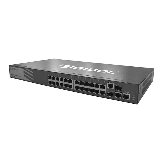
NTRODUCTION VERVIEW The DG-FS4526E is a Fast Ethernet Layer 2 switch with 24 10/100BASE-TX ports, and two Small Form Factor Pluggable (SFP) transceiver slots that operate in combination with 1000BASE-T ports 25~26 (see "Front and Rear Panels" on page 11). - Page 12 | Introduction HAPTER Overview WITCH RCHITECTURE The switch employs a wire-speed, non-blocking switching fabric. This permits simultaneous wire-speed transport of multiple packets at low latency on all ports. The switch also features full-duplex capability on all ports, which effectively doubles the bandwidth of each connection. This switch uses store-and-forward switching to ensure maximum data integrity.
-
Page 13: Description Of Hardware
| Introduction HAPTER Description of Hardware ESCRIPTION OF ARDWARE 10/100BASE-T P ORTS The switch contains 24 RJ-45 ports that operate at 10 Mbps, or 100 Mbps, half or full duplex. Because these ports support automatic MDI/MDI-X operation, you can use straight-through cables for all network connections to PCs or servers, or to other switches or hubs. -
Page 14: Figure 2: Port And System Status Leds
| Introduction HAPTER Description of Hardware Table 1: Supported SFP Transceivers Media Standard Fiber Diameter Wavelength (nm) Maximum Distance (microns) 1000BASE-LH 9/125 1310 35 km 1550 80 km 100BASE-FX 62.5/125 1300 2 km 1000BASE-T 100 m Maximum distance may vary for different SFP vendors. ORT AND YSTEM TATUS... -
Page 15: Table 2: Port Status Leds
| Introduction HAPTER Description of Hardware Table 2: Port Status LEDs Condition Status Fast Ethernet Ports (Ports 1-24) Link/Activity/ On/Flashing Amber Port has established a valid 10 Mbps network Speed connection. Flashing indicates activity. On/Flashing Green Port has established a valid 100 Mbps network connection. -
Page 16: Figure 3: Power Supply Inlet
| Introduction HAPTER Description of Hardware OWER UPPLY NLET There is one power inlet on the rear panel of the switch. The standard power inlet is for the AC power cord. Figure 3: Power Supply Inlet ROUNDING OINT To prevent accidental electrical shock or damage to your switch, it is recommended that you ground the switch to an earth point by attaching a grounding wire (not supplied) to the grounding point located next to the power inlet, with a metal screw. -
Page 17: Figure 5: Console Port
| Introduction HAPTER Description of Hardware ONSOLE This port is used to connect a console device to the access point through a serial cable. The console device can be a PC or workstation running a VT- 100 terminal emulator, or a VT-100 terminal. A crossover RJ-45 to DB-9 cable is supplied with the unit for connecting to the console port. - Page 18 | Introduction HAPTER Description of Hardware – 18 –...
-
Page 19: Network Planning
ETWORK LANNING NTRODUCTION TO WITCHING A network switch allows simultaneous transmission of multiple packets via non- crossbar switching. This means that it can partition a network more efficiently than bridges or routers. The switch has, therefore, been recognized as one of the most important building blocks for today’s networking technology. -
Page 20: Application Examples
Fast Ethernet ports, a Gigabit Ethernet port, or a plug-in SFP transceiver on the front panel. In the figure below, the DG-FS4526E is operating as a collapsed backbone for a small LAN. It is providing dedicated 10 Mbps full-duplex connections to workstations, 100 Mbps full-duplex connections to power users, and 1 Gbps full- duplex connections to servers. -
Page 21: Figure 7: Network Aggregation Plan
In the figure below, the 10/100BASE-TX ports on the switch are providing 100 Mbps connectivity for up to 24 segments, while the 1000BASE-T ports are providing connectivity for two Gigabit segments. Figure 7: Network Aggregation Plan DG-FS4526E 1000 Mbps Segments 10/100 Mbps... -
Page 22: Figure 8: Remote Connections With Fiber Cable
100BASE-FX (SMF) link up to 20 km. This allows the switches to serve as a collapsed backbone, providing direct connectivity for a widespread LAN. The figure below illustrates the DG-FS4526E connecting multiple segments with fiber cable. Figure 8: Remote Connections with Fiber Cable... -
Page 23: Figure 9: Making Vlan Connections
VLAN group to which it belongs. Untagged VLANs can be used for small networks attached to a single switch. However, tagged VLANs should be used for larger networks, and all the VLANs assigned to the inter-switch links. Figure 9: Making VLAN Connections DG-FS4526E R&D VLAN 1 Tagged... -
Page 24: Application Notes
| Network Planning HAPTER Application Notes PPLICATION OTES Full-duplex operation only applies to point-to-point access (such as when a switch is attached to a workstation, server, or another switch). When the switch is connected to a hub, both devices must operate in half-duplex mode. -
Page 25: Installing The Switch
NSTALLING THE WITCH ELECTING A Switch units can be mounted in a standard 19-inch equipment rack or on a flat surface. Be sure to follow the guidelines below when choosing a location. The site should: be at the center of all the devices you want to link and near a power outlet. -
Page 26: Ethernet Cabling
| Installing the Switch HAPTER Ethernet Cabling THERNET ABLING To ensure proper operation when installing the switch into a network, make sure that the current cables are suitable for 10BASE-T, 100BASE-TX, or 1000BASE-T operation. Check the following criteria against the current installation of your network: Cable type: Unshielded twisted pair (UTP) or shielded twisted pair (STP) cables with RJ-45 connectors;... -
Page 27: Equipment Checklist
Then, before beginning the installation, be sure you have all other necessary installation equipment. ACKAGE ONTENTS Managed 26-Port FE Switch (DG-FS4526E) RJ-45 to DB-9 console cable Four adhesive foot pads Grounding screw Bracket Mounting Kit, containing two brackets and eight screws for... -
Page 28: Mounting
| Installing the Switch HAPTER Mounting OUNTING The switch can be mounted in a standard 19-inch equipment rack, on a desktop or shelf, or on a wall. Mounting instructions for each type of site follow. OUNTING Before rack mounting the switch, pay particular attention to the following factors: Temperature: Since the temperature within a rack assembly may be higher than the ambient room temperature, check that the rack-environment... -
Page 29: Figure 11: Attaching The Brackets
| Installing the Switch HAPTER Mounting To rack-mount devices: Attach the brackets to the device using the screws provided in the Bracket Mounting Kit. Figure 11: Attaching the Brackets Mount the device in the rack, using four rack-mounting screws (not provided). -
Page 30: Figure 12: Installing The Switch In A Rack
| Installing the Switch HAPTER Mounting Figure 12: Installing the Switch in a Rack If installing a single switch only, turn to "Connecting to a Power Source" on page 45 at the end of this chapter. If installing multiple switches, mount them in the rack, one below the other. –... -
Page 31: Figure 13: Attaching The Adhesive Feet
| Installing the Switch HAPTER Mounting ESKTOP OR HELF OUNTING To attach the switch to a vertical surface: Attach the four adhesive feet to the bottom of the first switch. Figure 13: Attaching the Adhesive Feet Set the device on a flat surface near an AC power source, making sure there are at least two inches of space on all sides for proper air flow. -
Page 32: Installing An Optional Sfp Transceiver
| Installing the Switch HAPTER Installing an Optional SFP Transceiver SFP T NSTALLING AN PTIONAL RANSCEIVER Figure 14: Inserting an SFP Transceiver into a Slot The SFP slots support the following optional SFP transceivers: 1000BASE-SX 1000BASE-LX 1000BASE-LH 100BASE- FX To install an SFP transceiver, do the following: Consider network and cabling requirements to select an appropriate SFP transceiver type. -
Page 33: Connecting To A Power Source
| Installing the Switch HAPTER Connecting to a Power Source SFP transceivers are hot-swappable. The switch does not need to be powered off before installing or removing a transceiver. However, always first disconnect the network cable before removing a transceiver. SFP transceivers are not provided in the switch package. -
Page 34: Connecting To The Console Port
| Installing the Switch HAPTER Connecting to the Console Port ONNECTING TO THE ONSOLE This port is used to connect a console device to the access point through a serial cable. The console device can be a PC or workstation running a VT-100 terminal emulator, or a VT-100 terminal. - Page 35 | Installing the Switch HAPTER Connecting to the Console Port The serial port’s configuration requirements are as follows: Default Baud rate—115,200 bps Character Size—8 Characters Parity—None Stop bit—One Data bits—8 Flow control—none – 47 –...
- Page 36 | Installing the Switch HAPTER Connecting to the Console Port – 48 –...
-
Page 37: Making Network Connections
AKING ETWORK ONNECTIONS ONNECTING ETWORK EVICES This switch is designed to be connected to 10, 100, or 1000 Mbps network cards in PCs and servers, as well as to other switches and hubs. It may also be connected to remote devices using optional 1000BASE-SX, 1000BASE-LX, 1000BASE-LH, or 100BASE-FX SFP transceivers. -
Page 38: Figure 17: Making Twisted-Pair Connections
| Making Network Connections HAPTER Twisted-Pair Devices ONNECTING TO ERVERS UBS AND WITCHES Connect one end of a twisted-pair cable segment to the device’s RJ-45 connector. Figure 17: Making Twisted-Pair Connections If the device is a network card and the switch is in the wiring closet, attach the other end of the cable segment to a modular wall outlet that is connected to the wiring closet. -
Page 39: Figure 18: Network Wiring Connections
| Making Network Connections HAPTER Twisted-Pair Devices ETWORK IRING ONNECTIONS Today, the punch-down block is an integral part of many of the newer equipment racks. Actually it is a part of the patch panel. Instructions for making connections in the wiring closet with this type of equipment follows. Attach one end of a patch cable to an available port on the switch, and the other end to the patch panel. -
Page 40: Fiber Optic Sfp Devices
| Making Network Connections HAPTER Fiber Optic SFP Devices SFP D IBER PTIC EVICES An optional Gigabit SFP (1000BASE-SX, 1000BASE-LX, 1000BASE-LH, or 100BASE-FX) transceiver can be used for a backbone connection between switches, or for connecting to a high-speed server. Each single-mode fiber port requires 9/125 micron single-mode fiber optic cable with an LC connector at both ends. -
Page 41: Figure 19: Making Fiber Port Connections
| Making Network Connections HAPTER Fiber Optic SFP Devices Figure 19: Making Fiber Port Connections As a connection is made, check the Link LED on the switch corresponding to the port to be sure that the connection is valid. The 1000BASE-SX, 1000BASE-LX, 1000BASE-LH fiber optic ports operate at 1 Gbps, full duplex, with auto-negotiation of flow control. -
Page 42: Connectivity Rules
| Making Network Connections HAPTER Connectivity Rules ONNECTIVITY ULES When adding hubs (repeaters) to your network, please follow the connectivity rules listed in the manuals for these products. However, note that because switches break up the path for connected devices into separate collision domains, you should not include the switch or connected cabling in your calculations for cascade length involving other devices. -
Page 43: Table 7: Maximum 1000Base-Lx Gigabit Ethernet Cable Length
| Making Network Connections HAPTER Connectivity Rules Table 7: Maximum 1000BASE-LX Gigabit Ethernet Cable Length Fiber Size Fiber Bandwidth Maximum Cable Length Connector 9/125 micron single- 2 m - 5 km (7 ft - 3.2 miles) mode fiber Table 8: Maximum 1000BASE-LH Gigabit Ethernet Cable Length Fiber Size Fiber Bandwidth Maximum Cable Length... -
Page 44: Cable Labeling And Connection Records
| Making Network Connections HAPTER Cable Labeling and Connection Records ABLE ABELING AND ONNECTION ECORDS When planning a network installation, it is essential to label the opposing ends of cables and to record where each cable is connected. Doing so will enable you to easily locate inter-connected devices, isolate faults and change your topology without need for unnecessary time consumption. -
Page 45: A Troubleshooting
ROUBLESHOOTING IAGNOSING WITCH NDICATORS Table 12: Troubleshooting Chart Symptom Action Power LED is Off Check connections between the switch, the power cord and the wall outlet. Contact your dealer for assistance. Diag LED is Flashing Power cycle the switch to try and clear the condition. Amber If the condition does not clear, contact your dealer for assistance. -
Page 46: Power And Cooling Problems
| Troubleshooting PPENDIX Power and Cooling Problems OWER AND OOLING ROBLEMS If the power indicator does not turn on when the power cord is plugged in, you may have a problem with the power outlet, power cord, or internal power supply. -
Page 47: Cables And Pinouts
ABLES AND INOUTS WISTED ABLE AND SSIGNMENTS For 10/100BASE-TX connections, the twisted-pair cable must have two pairs of wires. For 1000BASE-T connections the twisted-pair cable must have four pairs of wires. Each wire pair is identified by two different colors. For example, one wire might be green and the other, green with white stripes. -
Page 48: Table 13: 10/100Base-Tx Mdi And Mdi-X Port Pinouts
| Cables and Pinouts PPENDIX Twisted-Pair Cable and Pin Assignments 10BASE-T/100BASE-TX P SSIGNMENTS Use unshielded twisted-pair (UTP) or shielded twisted-pair (STP) cable for RJ-45 connections: 100-ohm Category 3 or better cable for 10 Mbps connections, or 100-ohm Category 5 or better cable for 100 Mbps connections. Also be sure that the length of any twisted-pair connection does not exceed 100 meters (328 feet). -
Page 49: Figure 21: Straight-Through Wiring
| Cables and Pinouts PPENDIX Twisted-Pair Cable and Pin Assignments Figure 21: Straight-through Wiring EIA/TIA 568B RJ-45 Wiring Standard 10/100BASE-TX Straight-through Cable White/Orange Stripe Orange White/Green Stripe End A End B Blue White/Blue Stripe Green White/Brown Stripe Brown ROSSOVER IRING If the twisted-pair cable is to join two ports and either both ports are labeled with an “X”... -
Page 50: Table 14: 1000Base-T Mdi And Mdi-X Port Pinouts
| Cables and Pinouts PPENDIX Twisted-Pair Cable and Pin Assignments 1000BASE-T P SSIGNMENTS All 1000BASE-T ports support automatic MDI/MDI-X operation, so you can use straight-through cables for all network connections to PCs or servers, or to other switches or hubs. The table below shows the 1000BASE-T MDI and MDI-X port pinouts. -
Page 51: Fiber Standards
| Cables and Pinouts PPENDIX Fiber Standards 1000BASE-T DJUSTING XISTING ATEGORY ABLING TO If your existing Category 5 installation does not meet one of the test parameters for 1000BASE-T, there are basically three measures that can be applied to try and correct the problem: Replace any Category 5 patch cables with high-performance Category 5e or Category 6 cables. - Page 52 | Cables and Pinouts PPENDIX Fiber Standards Table 15: Fiber Standards (Continued) ITU-T Description Application Standard G.654 1550-nm Loss-Minimized Fiber Extended long-haul applications. Optimized for high-power Single-mode, 9/125-micron core transmission in the 1500 to 1600-nm region, with low loss in the 1550-nm band.
-
Page 53: Hardware Specifications
ARDWARE PECIFICATIONS HYSICAL HARACTERISTICS ORTS 24 10/100BASE-TX ports, with auto-negotiation 2 10/100/1000BASE-T shared with two SFP transceiver slots ETWORK NTERFACE Ports 1-24: RJ-45 connector, auto MDI/X 10BASE-T: RJ-45 (100-ohm, UTP cable; Category 3 or better) 100BASE-TX: RJ-45 (100-ohm, UTP cable; Category 5 or better) *Maximum Cable Length - 100 m (328 ft) Ports 25-26: RJ-45 connector, auto MDI/X 10BASE-T: RJ-45 (100-ohm, UTP cable;... - Page 54 | Hardware Specifications PPENDIX Physical Characteristics System: Power, Diag (Diagnostic), Port: status (link, speed and activity) EIGHT 1.7 kg (3.18 lbs) 44.0 x 21.0 x 4.4 cm (17.32 x 8.27 x 1.73 in.) EMPERATURE Operating: 0 to 50 °C (32 to 122 °F) Storage: -40 to 70 °C (-40 to 158 °F) UMIDITY Operating: 10% to 90% (non-condensing)
-
Page 55: Switch Features
| Hardware Specifications PPENDIX Switch Features WITCH EATURES ORWARDING Store-and-forward HROUGHPUT Wire speed ONTROL Full Duplex: IEEE 802.3x Half Duplex: Back pressure ANAGEMENT EATURES ANAGEMENT Web, Telnet, SSH, or SNMP manager ANAGEMENT RJ-45 console port OFTWARE OADING HTTP, HTTPS, TFTP in-band, or XModem out-of-band –... - Page 56 | Hardware Specifications PPENDIX Management Features – 68 –...
-
Page 57: Glossary
LOSSARY 10BASE-T IEEE 802.3 specification for 10 Mbps Ethernet over two pairs of Category 3, 4, or 5 UTP cable. 100BASE-FX IEEE 802.3 specification for 100 Mbps Ethernet over two strands of 50/125, 62.5/125 micron, or 9/125 micron core fiber cable. 100BASE-TX IEEE 802.3u specification for 100 Mbps Ethernet over two pairs of Category 5 UTP cable. - Page 58 LOSSARY EGOTIATION Signalling method allowing each node to select its optimum operational mode (e.g., speed and duplex mode) based on the capabilities of the node to which it is connected. ANDWIDTH The difference between the highest and lowest frequencies available for network signals.
- Page 59 LOSSARY IGABIT THERNET A 1000 Mbps network communication system based on Ethernet and the CSMA/ CD access method. IEEE Institute of Electrical and Electronic Engineers. IEEE 802.3 Defines carrier sense multiple access with collision detection (CSMA/CD) access method and physical layer specifications. IEEE 802.3 Defines CSMA/CD access...
- Page 60 LOSSARY (LAN) OCAL ETWORK A group of interconnected computer and support devices. (MAC) EDIA CCESS ONTROL A portion of the networking protocol that governs access to the transmission medium, facilitating the exchange of data between network nodes. An acronym for Management Information Base. It is a set of database objects that contains information about the device.
- Page 61 LOSSARY LAN (VLAN) IRTUAL A Virtual LAN is a collection of network nodes that share the same collision domain regardless of their physical location or connection point in the network. A VLAN serves as a logical workgroup with no physical barriers, allowing users to share information and resources as though located on the same LAN.
- Page 62 LOSSARY – 74 –...
-
Page 63: Index
NDEX equipment checklist UMERICS Ethernet connectivity rules 10 Mbps connectivity rules 100 Mbps connectivity rules 1000 Mbps connectivity rules 1000BASE-LH fiber cable Lengths Fast Ethernet connectivity rules 1000BASE-LX fiber cable Lengths features 1000BASE-SX fiber cable Lengths front panel of switch 1000BASE-T full duplex connectivity pin assignments... - Page 64 NDEX network connections examples package contents pin assignments 1000BASE-T 10BASE-T/100BASE-TX console port ports, connecting to power, connecting to rack mounting rear panel of switch RJ-45 port connections pinouts screws for rack mounting SFP transceiver slots site selelction SNMP agent specifications environmental power status LEDs...
- Page 65 DG-FS4526E E042012 HW-R01...
- Page 66 ECTION – 78 –...
Need help?
Do you have a question about the DG-FS4526E and is the answer not in the manual?
Questions and answers