Table of Contents
Advertisement
Quick Links
Advertisement
Table of Contents

Related Manuals for Frontier ST0320


Summary of Contents for Frontier ST0320
- Page 1 ST0320 Snow Thrower OPERATOR’S MANUAL MTF-041007C...
-
Page 2: Responsibility Of The Owner
INTRODUCTION Congratulations on your purchase of a Frontier Snowthrower. It has been designed, engineered and manufactured to give you the best possible dependability and performance. However, like all mechanical products, your machine will occasionally re- quire adjustment and maintenance. This handbook should be read before operating or performing and adjustments on your machine. -
Page 3: Rules For Safe Operation
RULES FOR SAFE OPERATION IMPORTANT WARNING: Always disconnect the spark plug wire and place it where it cannot make contact with spark plug to prevent accidental starting during: Preparation, Maintenance, or Storage of your snowthrower. Safe Operation Practices for Snowthrowers As Recommended By: American National Standards Institute. -
Page 4: Maintenance And Storage
RULES FOR SAFE OPERATION Maintenance And Storage 7. Stop the engine (motor) whenever you leave the operat- ing position, before unclogging the auger/impeller hous- 1. Check shear bolts and other bolts at frequent intervals ing or discharge chute and when making any repairs, for proper tightness to be sure the equipment is in safe adjustments, or inspections. -
Page 5: Table Of Contents
TABLE OF CONTENTS SAFETY DECALS ..........WARRANTY . -
Page 6: Safety Decals
SAFETY DECALS the meaning, then thoroughly read all safety and operation WARNING: If safety decals are dam- instructions in this Owner’s Manual or contact your local aged or missing, replace immediately. dealer. If any safety decals become worn or damaged and cannot Look for this symbol to indicate important safe- be read, order replacement decals from your local dealer. -
Page 7: Warranty
THREE YEAR LIMITED WARRANTY Murray warrants to the original purchaser of this Frontier Branded Snowthrower that this unit shall be free from defects in material and workmanship under normal use and service for a period of Three (3) Year from the date of purchase; however,... -
Page 8: Assembly
ASSEMBLY WARNING: Always wear safety glasses or eye PARTS BAGS CONTENTS: shields while assembling the snowthrower. 1 - 2.6 ounces 2-cycle oil 1 - Owner’s Manual Figure 2 shows the snow thrower in the operating position. TOOLS REQUIRED FOR ASSEMBLY References to the right or left hand side of the snow throw- 1-Knife er are from the viewpoint of the operator’s position behind... -
Page 9: How To Assemble The Lower Chute
ASSEMBLY HOW TO ASSEMBLE THE LOWER CHUTE For shipping purposes, some models are shipped with the rear nut and bolt removed from the lower chute. If the low- er chute is not attached, assemble as follows. Bolt 1. Use the bolt and nut found in the parts bag to attach the lower chute. -
Page 10: Operation
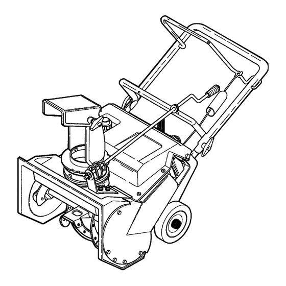
OPERATION KNOW YOUR SNOW THROWER READ THIS OWNER’S MANUAL AND SAFETY RULES BEFORE OPERATING YOUR SNOW THROWER. Compare the illustrations with your SNOW THROWER to familiarize yourself with the location of various controls and adjustments. Save this manual for future reference. Chute Control Rod Auger Drive Lever Recoil... -
Page 11: Snow Blower Operation
OPERATION SNOWTHROWER OPERATION NOTE: If the snow thrower continues to slowly move forward, see “How To Adjust The Auger Control The most effective use of the snowthrower will be established Cable” in the Service And Adjustment Section. by experience, taking into consideration the terrain, wind 2. -
Page 12: How To Mix The Fuel Mixture
OPERATION BEFORE STARTING THE ENGINE Mix gasoline and oil as follows: WARNING: Experiences indicates that alcohol 1. Pour one (1) U.S. quart of fresh, clean, unleaded auto- blended fuels (called gasohol or those using motive gasoline into a one gallon size gasoline con- ethanol or methanol) can attract moisture tainer. -
Page 13: Before Starting The Engine
OPERATION BEFORE STARTING THE ENGINE 1. Before you service or start the engine, familiarize yourself with the snow thrower. Be sure you understand the func- tion and location of all controls. 2. Be sure that all fasteners are tight. 3. Before starting the engine, make sure all controls operate correctly. -
Page 14: How To Remove Snow From The Auger Housing
OPERATION HOW TO REMOVE SNOW FROM THE AUGER HOUSING WARNING: Do not attempt to remove snow or debris that may become lodged in auger housing without taking the following precau- tions. 1. Release the auger drive lever. 2. Remove the ignition key. 3. -
Page 15: Service Recommendations
SERVICE RECOMMENDATIONS SERVICE RECOMMENDATIONS FIRST BEFORE EVERY EVERY EVERY BEGINNING EACH EACH BEFORE PROCEDURE HOUR OFTEN HOURS HOURS HOURS SEASON STORAGE Tighten all screws and nuts √ √ √ Lubricate Chute Control √ √ Flange Check Auger Drive Cable Adjustment √... -
Page 16: Maintenance
MAINTENANCE HOW TO REMOVE THE TOP COVER Top Cover 1. Remove the screws from the top cover. 2. Remove the top cover. 3. To install the top cover, reverse the above steps. Screws Figure 10 HOW TO REMOVE THE BELT COVER 1. -
Page 17: How To Adjust The Chute Crank
MAINTENANCE WARNING: To prevent accidental starting when making any adjustments or repairs, always dis- connect the spark plug wire and place it where it cannot make contact with the spark plug . HOW TO ADJUST THE CHUTE CRANK Crank Adjusting Bracket If the chute crank will not rotate fully to the left or right, adjust as follows. -
Page 18: How To Replace The Drive Belt
MAINTENANCE HOW TO REPLACE THE DRIVE BELT Belt Guide Engine PUlley The drive belt is of special construction and must be re- Idler Pulley placed with original factory replacement belt available from your nearest authorized service center. Drive Belt 1. Remove the belt cover. See “How To Remove The Belt Cover”. -
Page 19: How To Replace The Auger
MAINTENANCE HOW TO REPLACE THE AUGER 1. Remove the belt cover. See “How To Remove The Belt 5. Remove the fasteners from the bearing assembly. Re- Cover”. move the bearing assembly from the auger housing. 2. Remove the drive belt. See “How To Replace The Drive 6. -
Page 20: To Adjust The Carburetor
MAINTENANCE TO ADJUST THE CARBURETOR The carburetor is not adjustable. Engine performance should not be affected at altitudes up to 7,000 feet. For operation at higher elevations, contact your nearest autho- rized service center. IMPORTANT: Never tamper with the engine governor, which is factory set for proper engine speed. -
Page 21: Storage
STORAGE OFF SEASON STORAGE 5. Insure that all nuts, bolts, and screws are securely fas- tened. Inspect all visible moving parts for damage, WARNING: Never store the engine, with fuel in breakage, and wear. Replace if necessary. the tank, indoors or in a poor ventilated enclo- sure where fuel fumes could reach an open 6. -
Page 22: Trouble Shooting Chart
If you have any questions concerning parts, service, or technical data, contact your nearest John Deere/Frontier dealer. For complete warranty information refer to the warranty in the Owner’s Information section of this manual. -
Page 23: Replacement Parts
REPLACEMENT PARTS WE RECOMMEND JOHN DEERE/FRONTIER quality parts and lubricants available at your John Deere/Frontier dealer. PART NUMBERS MAY CHANGE. When you order re- placement parts, use the part numbers listed below and on the following pages. If a part number changes, your John Deere/Frontier dealer will have the latest part number. -
Page 24: Parts Schematics
FRONTIER MODEL ST0320 FACTORY MODEL 620351x16NB ENGINE ASSEMBLY Key No. Part No. Description ------ ENGINE MT180077 SCREW, 5/16-18 X.75 MT018x16 WASHER MT71071 WASHER, FLAT MT313440 GUIDE, BELT MT710312 SCREW MT339017 SPRING, IDLER BRAKE MT1501013 ASSY, IDLER BRAKE ARM MT333594 BOLT... - Page 25 FRONTIER MODEL ST0320 FACTORY MODEL 620351x16NB FRAME COMPONENTS ASSEMBLY Key No. Part No. Description MT760272E701 FRAME SIDE SUPPORT RH MT760271E701 FRAME SIDE SUPPORT LH MT760169 ROD, SUPPORT MT71063 WASHER, HVSPTLK MT71044 NUT, 3/8-16 REGHEX MT578093E701 BRACKET, GAS TANK MT302628 SCREW, 1/4-20X.75...
- Page 26 FRONTIER MODEL ST0320 FACTORY MODEL 620351x16NB TOP COVER ASSEMBLY MTF-041007C...
-
Page 27: Top Cover Assembly
FRONTIER MODEL ST0320 FACTORY MODEL 620351x16NB TOP COVER ASSEMBLY Key No. Part No. Description MT302265 COVER, BOTTOM MT313674 SCREW, 1/4-20X1.25 MT71067 WASHER, FLAT .281X.63X.065 MT15x143 NUT, 1/4-20 YZ MT326212 COVER, CARB MT313685 SCREW, 1/4-14X.75 MT578109 NUT, 1/4-10 SPEED J TYPE MT57587 GROMMET &... - Page 28 FRONTIER MODEL ST0320 FACTORY MODEL 620351x16NB AUGER HOUSING 520-10 520-6 520-2 520-8 MTF-041007C...
- Page 29 FRONTIER MODEL ST0320 FACTORY MODEL 620351x16NB AUGER HOUSING Key No. Part No. Description MT330312 HOUSING, ASSY MT302628 SCREW, 1/4-20X.75 MT71067 WASHER, FLAT .281X.63X.065 MT15x143 NUT, HEX 1/4-20 YZ MT579052 SCREW, 1/4-20X.63 MT331126 BRACKET, STOP MT331211 WASHER, FLAT .333X.87X.119 MT780029 NUT, 1/4-20 HEX NYLOCK...
- Page 30 FRONTIER MODEL ST0320 FACTORY MODEL 620351x16NB DISCHARGE CHUTE Key No. Part No. Description MT314239 RING, CHUTE MT711752 SCREW, #10X.50 MT577021 GUIDE, CHUTE MT334234 CHUTE, LOWER MT313686 SCREW 1/4-20X.50 MT15x143 NUT, 1/4-2 YZ MT325847 CHUTE, UPPER MT308931 WIRE, HINGE MT302843 BOLT, CARRIAGE 5/16-18X1.25 MT71071 WASHER, FLAT .349X.69X.066...
- Page 31 FRONTIER MODEL ST0320 FACTORY MODEL 620351x16NB WHEELS Key No. Part No. Description MT1501923 AXLE SHAFT MT583409 WASHER, FLAT .391X1.00X1.25 MT1501689 TIRE & RIM MT583409 WASHER, FLAT .391X1.00X.125 MT577598 RING, RET E MTF-041007C...
- Page 32 FRONTIER MODEL ST0320 FACTORY MODEL 620351x16NB HANDLE ASSEMBLY MTF-041007C...
-
Page 33: Handle Assembly
FRONTIER MODEL ST0320 FACTORY MODEL 620351x16NB HANDLE ASSEMBLY Key No. Part No. Description MT760774 CABLE, UPPER MT313441 BRACKET, CABLE ADJ MT760773 CABLE, LOWER CONTROL MT308146 BOOT, CLUTCH SPRING MT313471 SPRING, EXTENSION MT313487E701 HANDLE, LOWER MT313674 SCREW, 1/4-20X1.25 MT71067 WASHER, FLAT... - Page 34 FRONTIER MODEL ST0320 FACTORY MODEL 620351x16NB CHUTE ROD ASSEMBLY Key No. Part No. Description MT314996 ROD, ASSY UPPER CHUTE CONTROL MT71072 WASHER, FLAT .406X.81X.066 MT71082 PIN, COTTER MT313431 WASHER, CURVED SPRING MT71072 WASHER, FLAT .406X.81X.066 MT57082 KNOB, SLEEVE MT331532 NUT, PUSH MT313712 BOLT, EYE 3/8-16X2.00...
- Page 35 FRONTIER MODEL ST0320 FACTORY MODEL 620351x16NB DECALS Key No. Part No. Description MT48x5258 DECAL, THROWN OBJECTS MT48x5642 DECAL, DANGER STOP ENGINE MT337524 DECAL, STOP LEVER MT48x2036 DECAL, ROTATING AUGER MT48x5639 DECAL, TECUMSEH PRODUCTS CO. MT69880 DECAL, HOT MUFFLER MT318494 DECAL, CHOKE ON/OFF...
-
Page 36: Specifications
SPECIFICATIONS ST0320 Engine Tecumseh Snow King 2-Cycle Horsepower 3.5 hp Starter Recoil Fuel Capacity 1.0 quart Drive System Auger Tire Diameter 7” Clearing Width 20” 10.25” Housing Height Auger Diameter 9” Auger Type Rubber-edged Chute Rotation Remote Chute Turning Radius...
Need help?
Do you have a question about the ST0320 and is the answer not in the manual?
Questions and answers